For 1990-2009 cars only
Removal Procedure
- With the engine OFF, press on the brake pedal several times in order to remove vacuum from the vacuum brake booster.
- Remove the brake master cylinder. Refer to Master Cylinder Replacement.
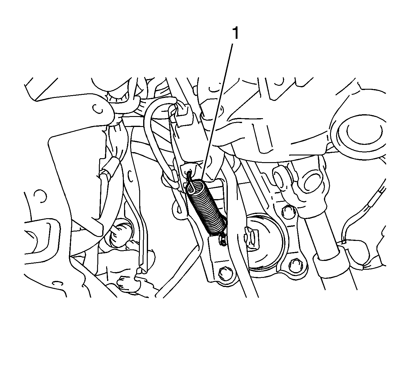
- Remove the brake pedal return spring (1) from the brake pedal support.
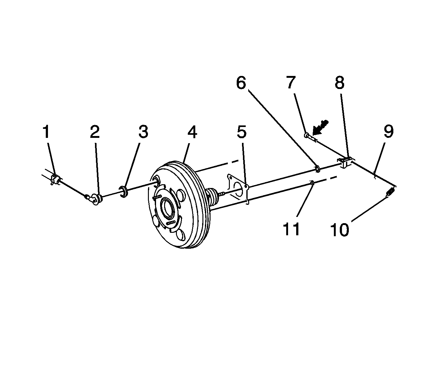
- Remove the clip (10) from the push rod clevis pin (7).
- Remove the push rod clevis pin and separate the push rod clevis (8) from the brake pedal.
- Loosen the hose clamp (1) and remove the vacuum hose from the check valve (2).
- Remove the check valve from the booster (4).
- Remove the check valve grommet (3) from the booster.
- Separate the left front brake pipe from the left front brake hose.
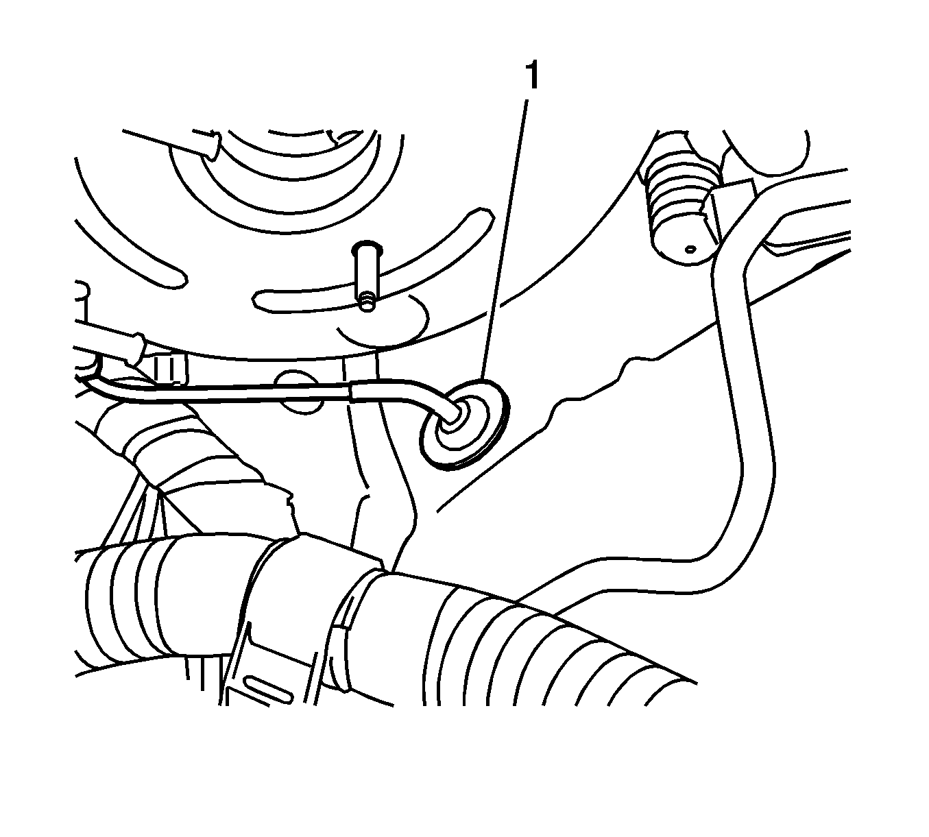
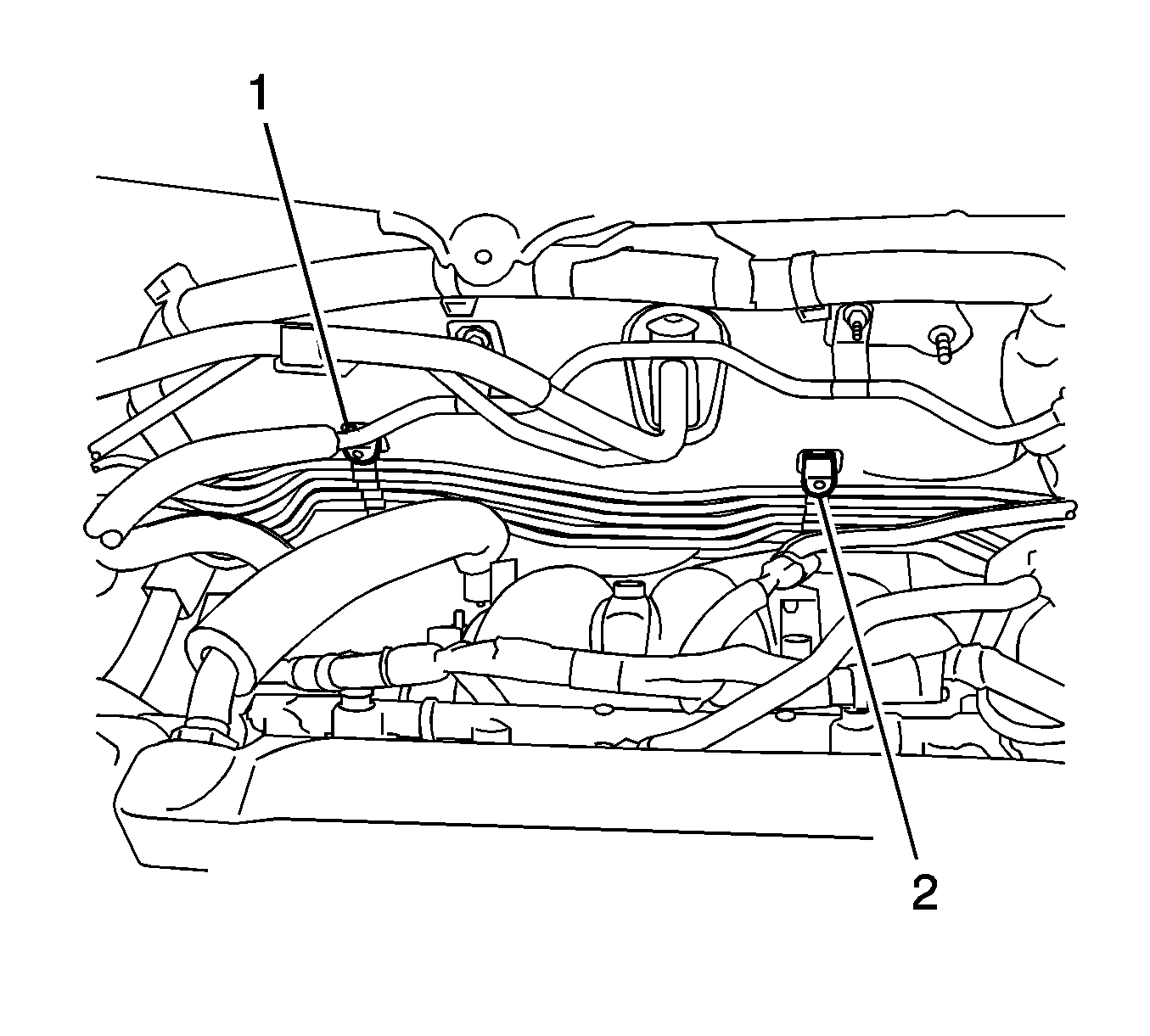
- Remove the grommet (1) and the left front brake pipe from the body.
- Disengage the 2 clamps (1, 2) and separate the brake pipes from the body.
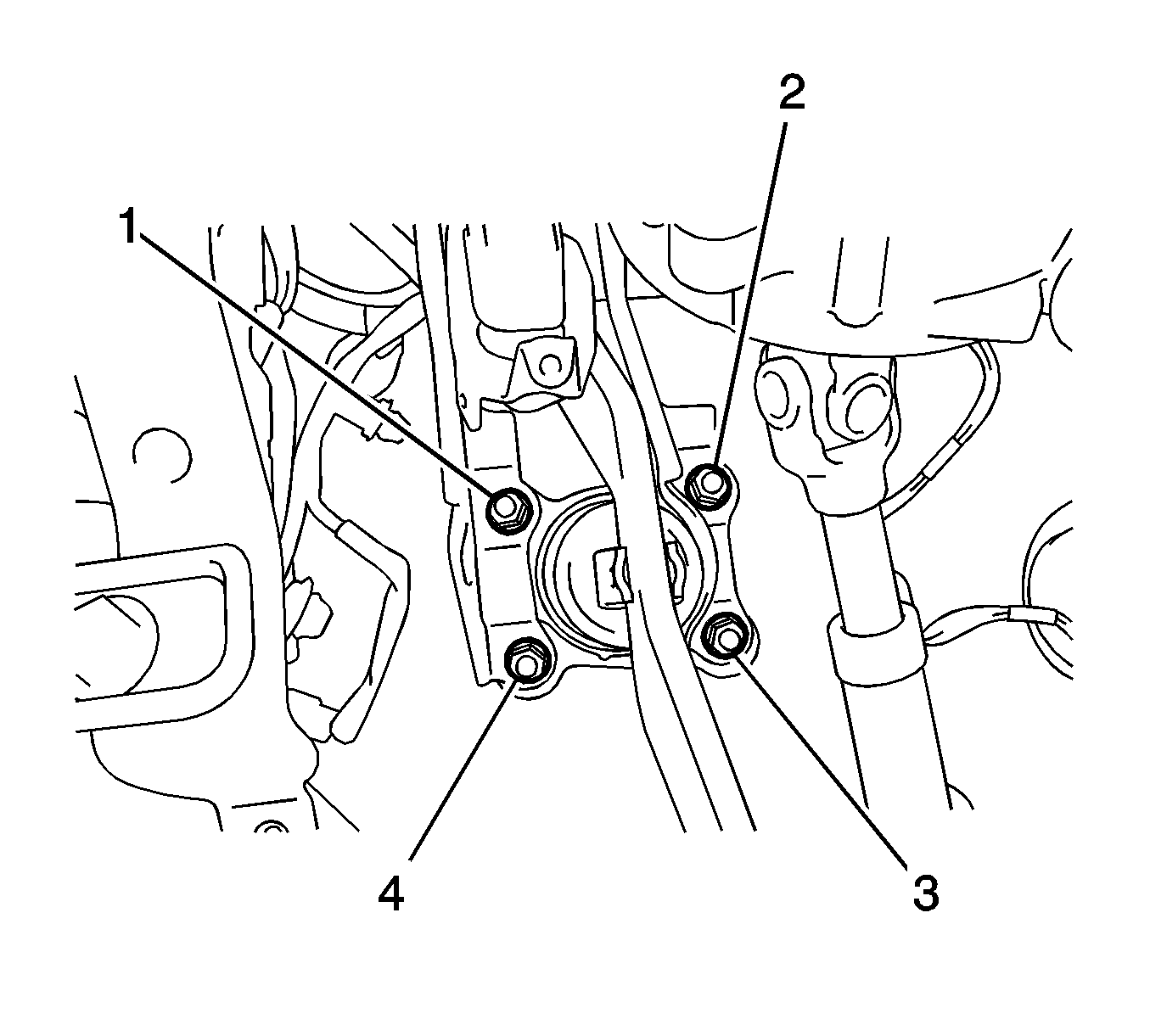
- Remove the 4 nuts (1, 2, 3, 4) from the booster.
- Remove the booster from the body.
- Remove the gasket from the booster.
- Remove the lock nut from the push rod.
- Remove the clevis from the push rod.
Warning: Refer to Brake Fluid Irritant Warning in the Preface section.
Caution: Refer to Brake Fluid Effects on Paint and Electrical Components Caution in the Preface section.
Caution: Internal components of this booster are not serviceable. The housing must not be unstaked and separated. Separating the housing will cause permanent deformation, preventing the booster from holding proper volume.
Discard the grommet.

Discard the gasket.
Installation Procedure
- Install the push rod lock nut (6) to the push rod.
- Install the push rod clevis (8) to the push rod.
- Install a NEW gasket (5) to the booster (4).
- Install the booster to the body.
- Install and tighten the 4 nuts (11) to 13 N·m (115 lb in).
- Engage the 2 clamps (1, 2) in order to retain the brake pipes to the body.
- Install the left front brake pipe and the grommet (1) to the body.
- Using a torque wrench with a fulcrum length of 250 mm (9.84 in) and a union nut wrench parallel to the torque wrench, install the left front brake hose to the left front brake pipe and tighten to 14 N·m (124 lb in).
- Install a NEW check valve grommet to the booster.
- Install the check valve to the booster.
- Install the vacuum hose to the booster.
- Install the hose clamp in order to retain the vacuum hose to the check valve.
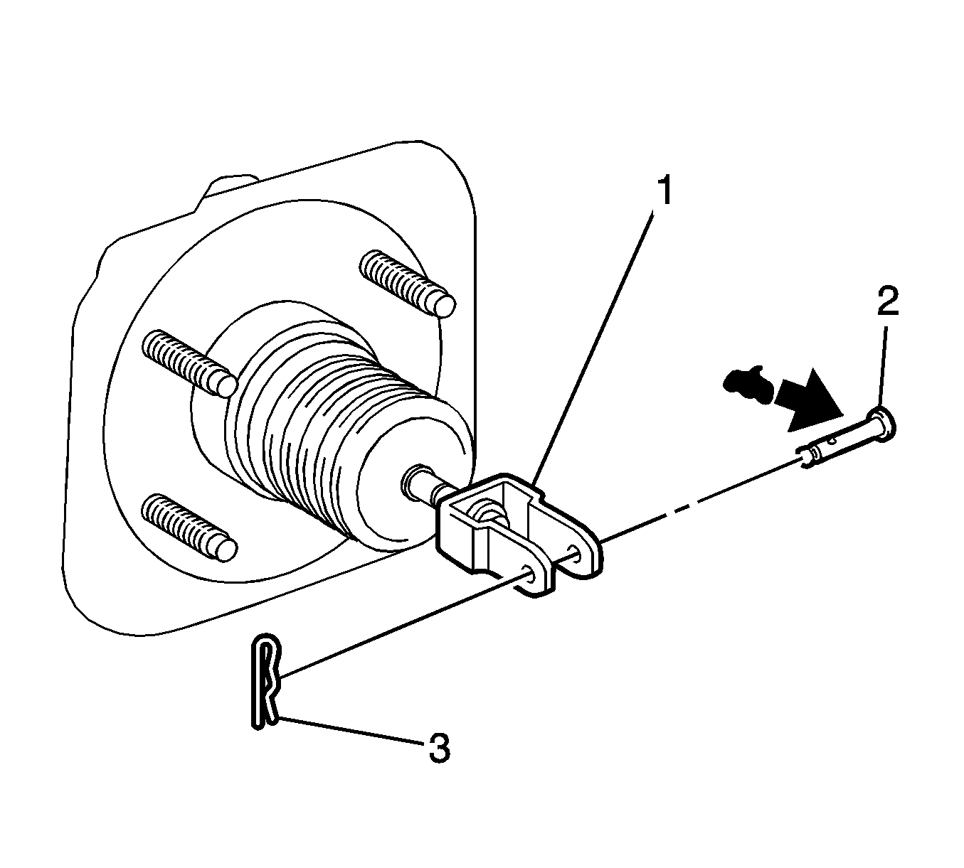
- Apply lithium soap base glycol grease to the push rod clevis pin (2).
- Install the push rod clevis (1) to the brake pedal.
- Install the push rod clevis pin.
- Install the clip (3) to the push rod clevis pin.
- Install the brake pedal return spring (1) between the brake pedal support and the push rod clevis.
- Install the brake master cylinder. Refer to Master Cylinder Replacement.
- Measure the brake pedal height and travel. Refer to Brake Pedal Travel Measurement and Inspection.
- If the brake pedal height and travel require adjustment, turn the push rod.
- Tighten the push rod clevis lock nut to 26 N·m (19 lb ft).

Note: Do not tighten the push rod lock nut yet. Brake pedal height adjustment is necessary.
Caution: Refer to Fastener Caution in the Preface section.


