Removal Procedure
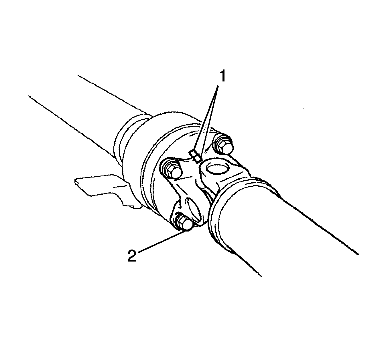
- Place matchmarks (1) on both the flanges.
- Remove the nuts, bolts and washers.
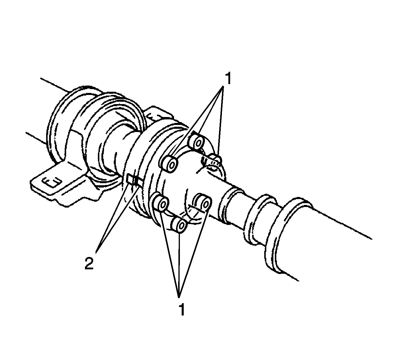
- Place matchmarks (2) on the rear flange and rear propeller shaft.
- Using a hexagon wrench (6 mm), remove the bolts and washers and remove the intermediate shaft from the rear propeller shaft.
- Using a hammer and a chisel, loosen the staked part of the nut.
- Hold the universal joint flange and remove the nut and washer.
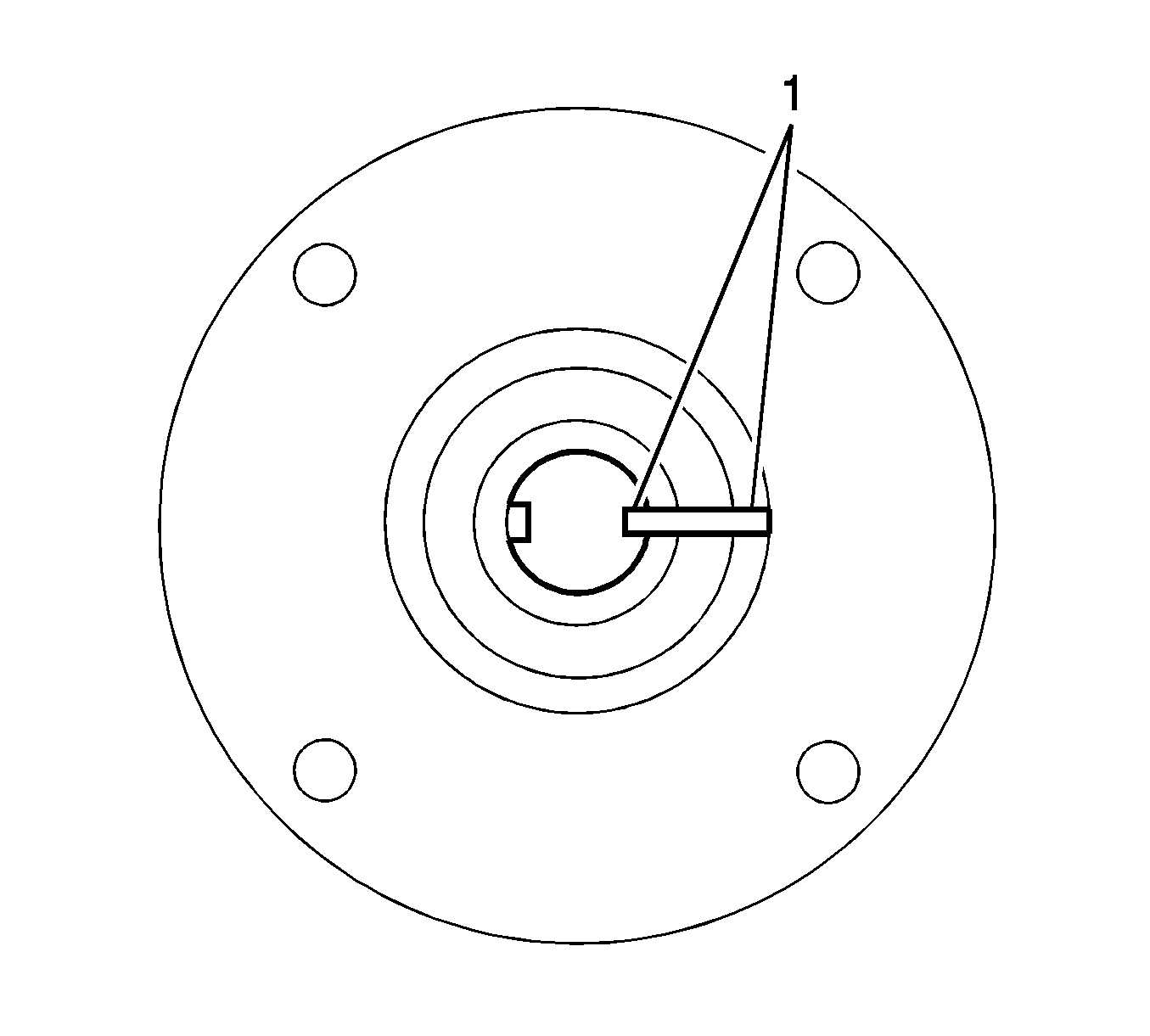
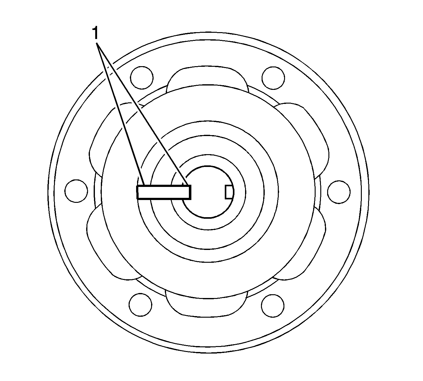
- Place matchmarks (1) on the universal joint flange and intermediate shaft.
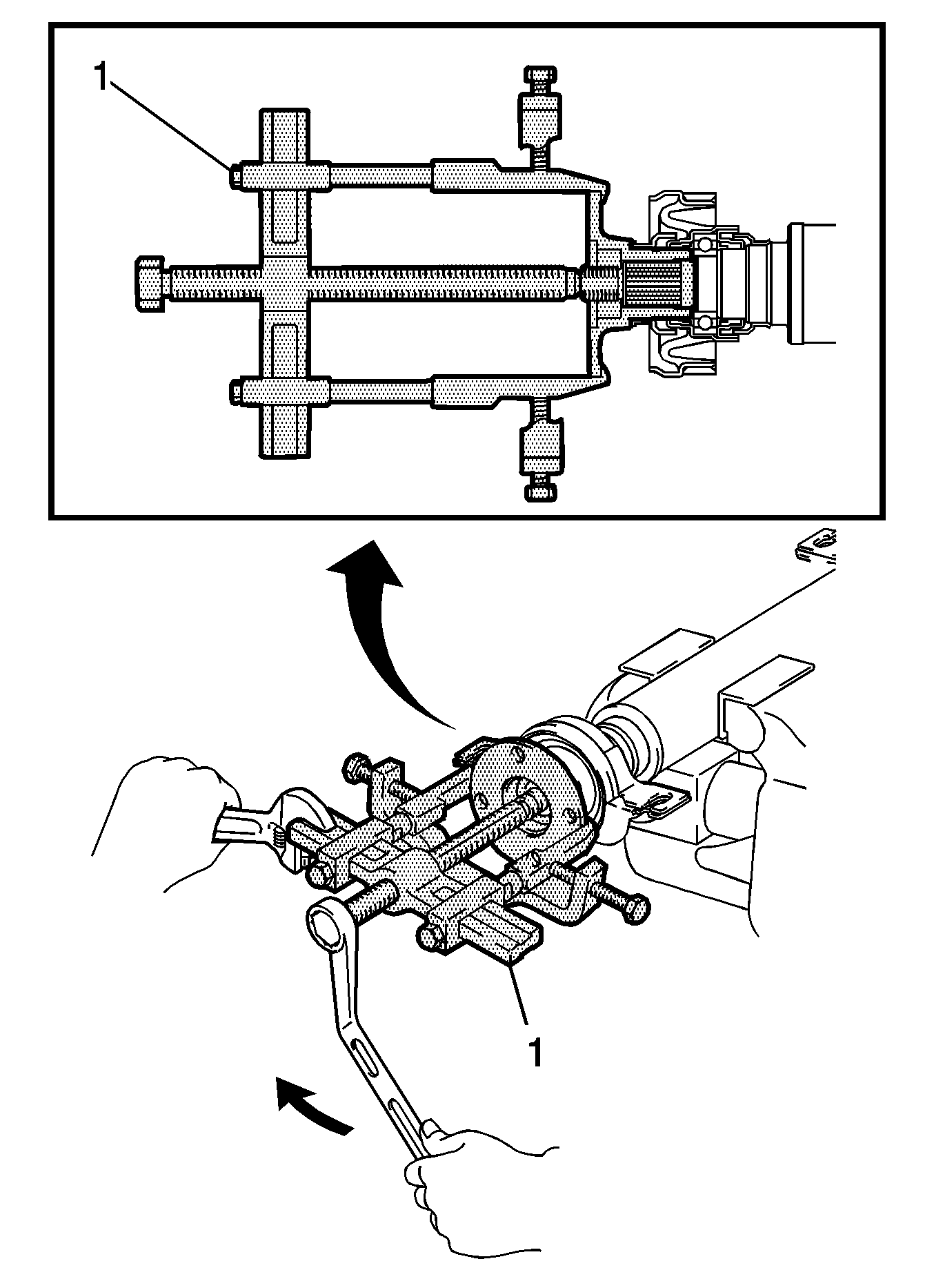
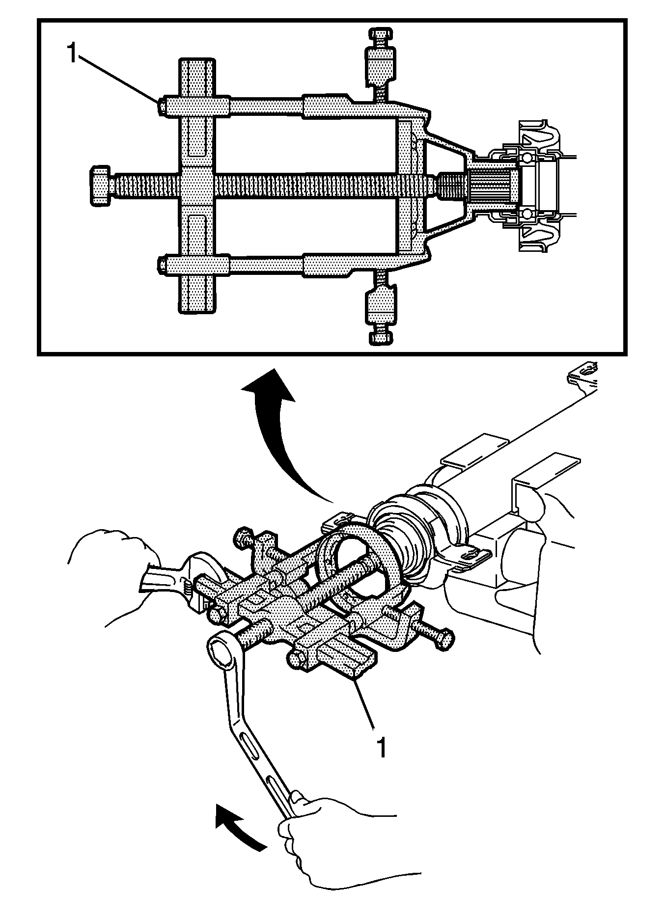
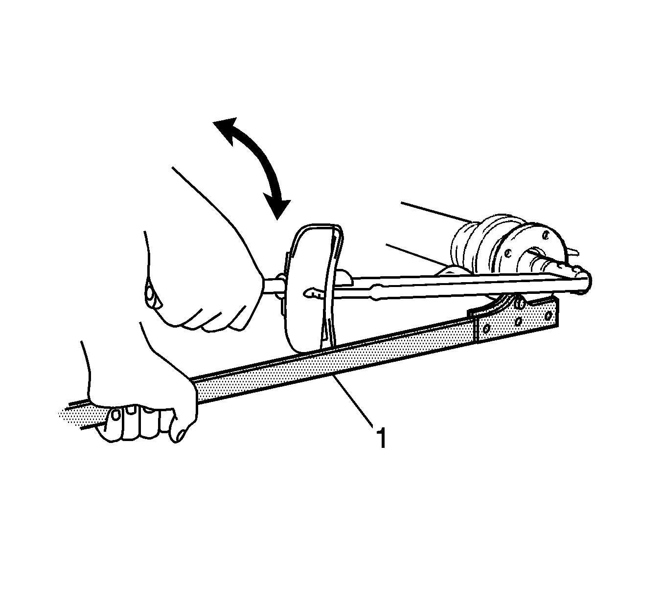
- Hold the intermediate shaft in a vise using aluminum plates, using a suitable puller (1), remove the universal joint flange.
- Remove the No. 1 center support bearing assembly and washer.
- Using a hammer and a chisel, loosen the staked part of the nut.
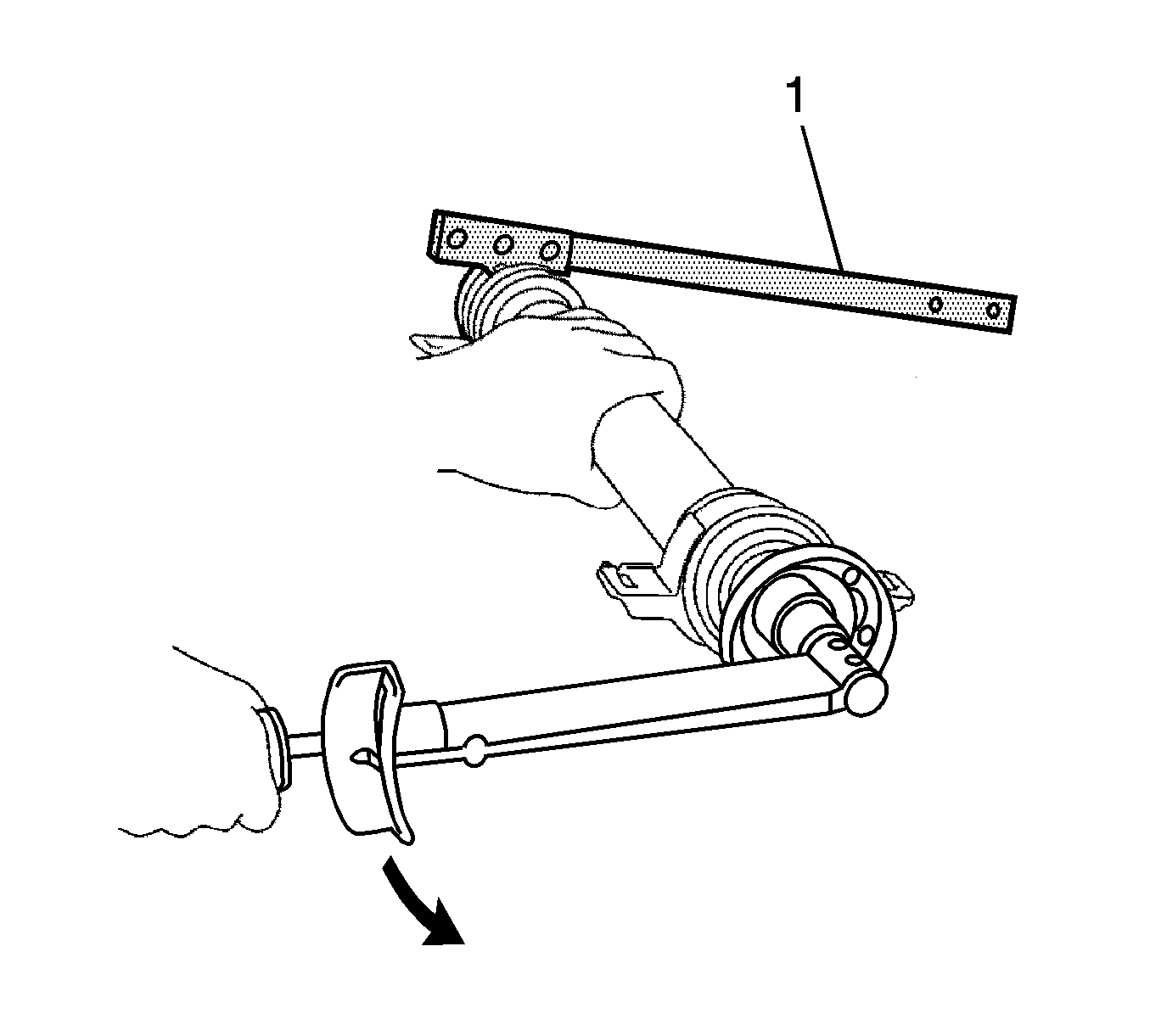
- Hold the universal joint flange with a suitable tool (1) then remove the nut and washer.
- Place matchmarks (1) on the universal joint flange and intermediate shaft.
- Hold the intermediate shaft in a vise using aluminum plates, using a suitable puller (1), remove the universal joint flange.
- Remove the No. 1 center support bearing assembly and washer.
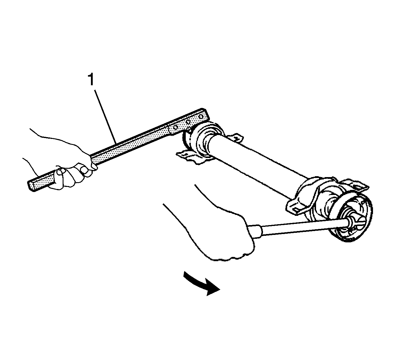
- Check the universal joint axial play by turning the flange while holding the shaft tightly.
- Using a dial indicator, inspect the intermediate shaft sub-assembly.
- If the shaft runout is greater than the maximum, replace the propeller shaft with the center bearing shaft as an assembly.
- Using a dial indicator, inspect the front side of the universal joint flange runout in the vertical direction.
- Using a dial indicator, inspect the rear side of the universal joint flange runout in the vertical direction.
- Using a dial indicator, inspect the rear side of the universal joint flange runout in the horizontal direction.
- Using a dial indicator, inspect the propeller shaft assembly.
- If the shaft runout is greater than the maximum, replace the propeller with the center bearing shaft assembly.
- Using a dial indicator, inspect the rear propeller shaft sub-assembly.
- If the shaft runout is greater than the maximum, replace the propeller shaft with center bearing shaft as an assembly.
- Turn the No. 1 center support bearing assembly by hand while applying force in the rotation direction. Check that the bearing turns smoothly.
- Check that the seals and bracket are not cracked or damaged.
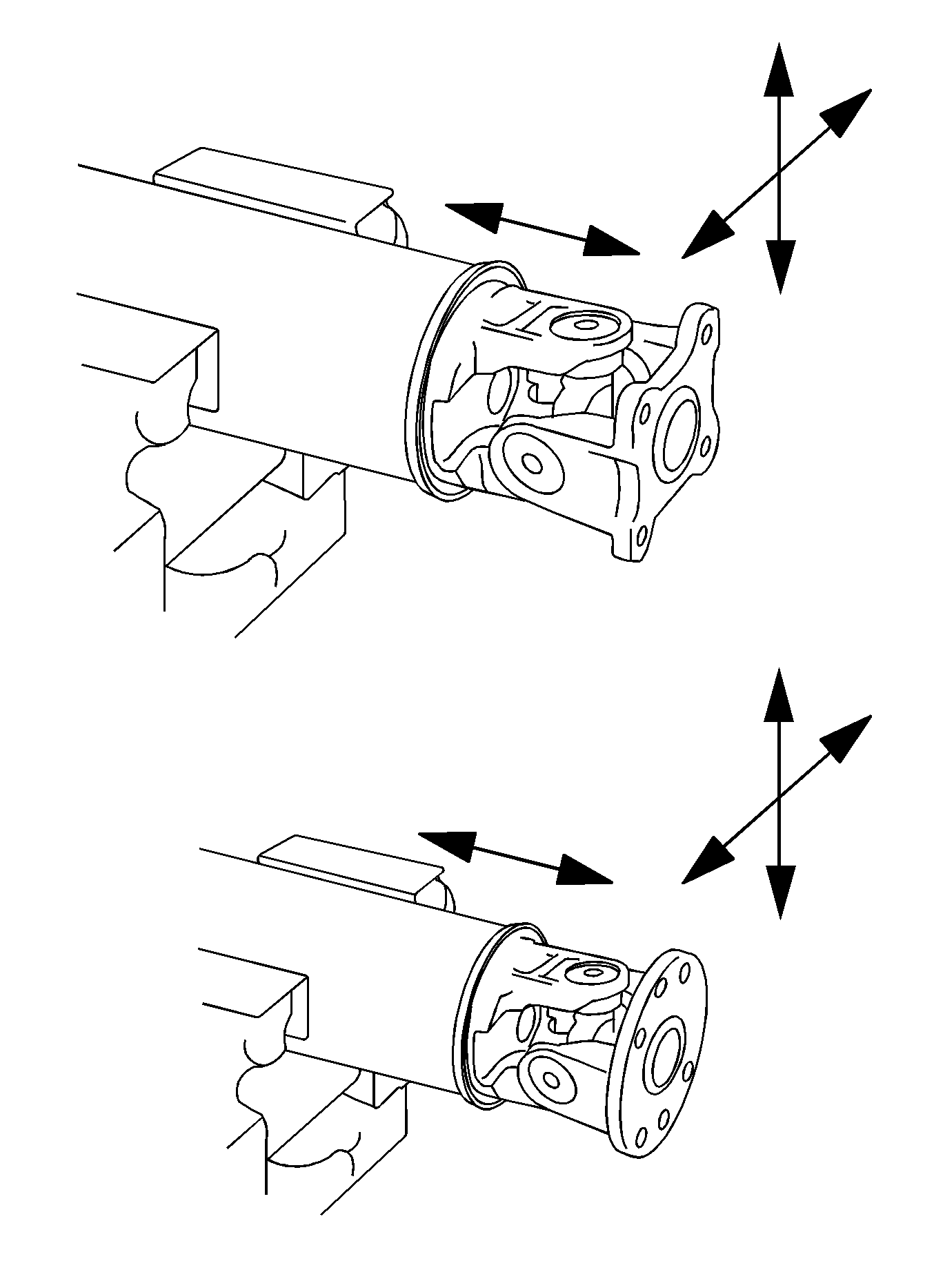
If damaged or worn, replace the propeller shaft with the center bearing shaft as an assembly.
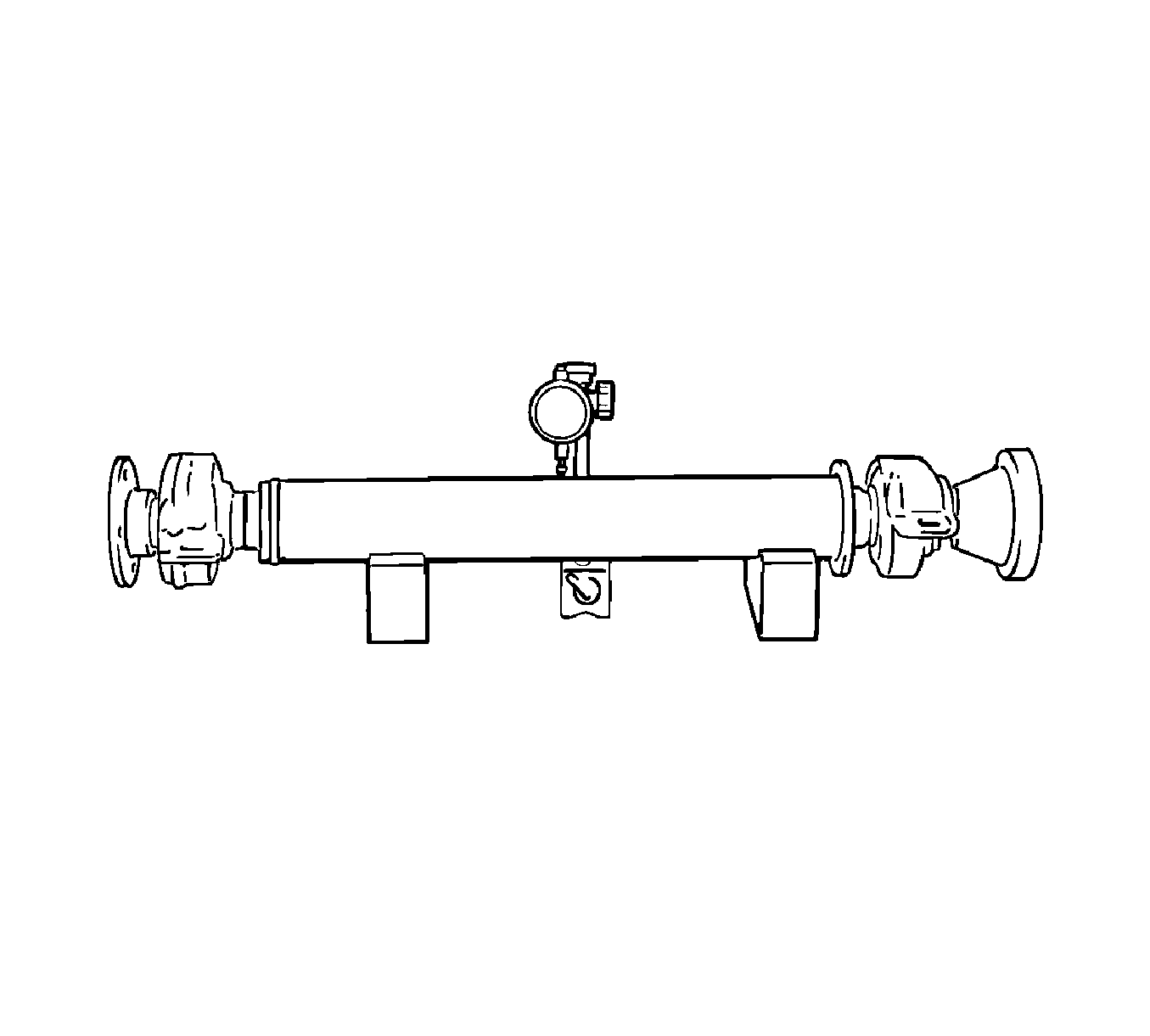
Note: The dial indicator must be set at a right angle to the center of the intermediate shaft.
Specification
Maximum runout - 0.4 mm (0.016 in)
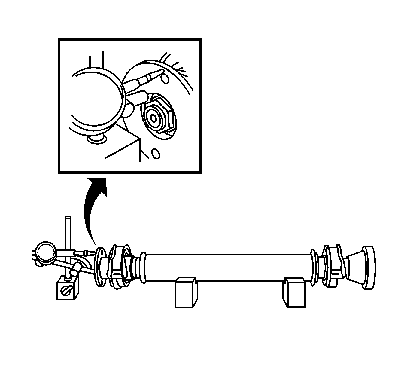
Specification
Maximum runout - 0.1 mm (0.004 in)
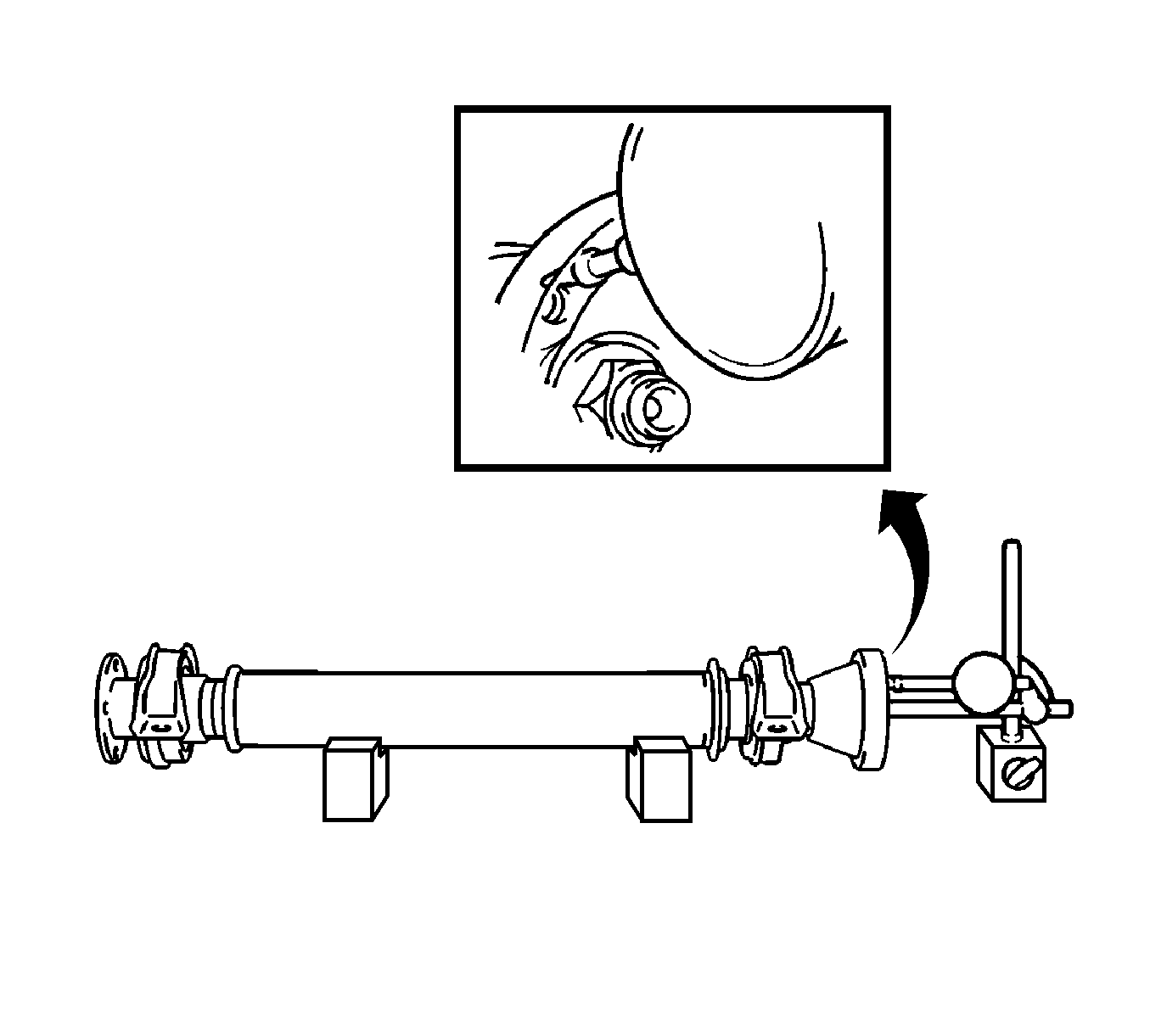
Specification
Maximum runout - 0.1 mm (0.004 in)
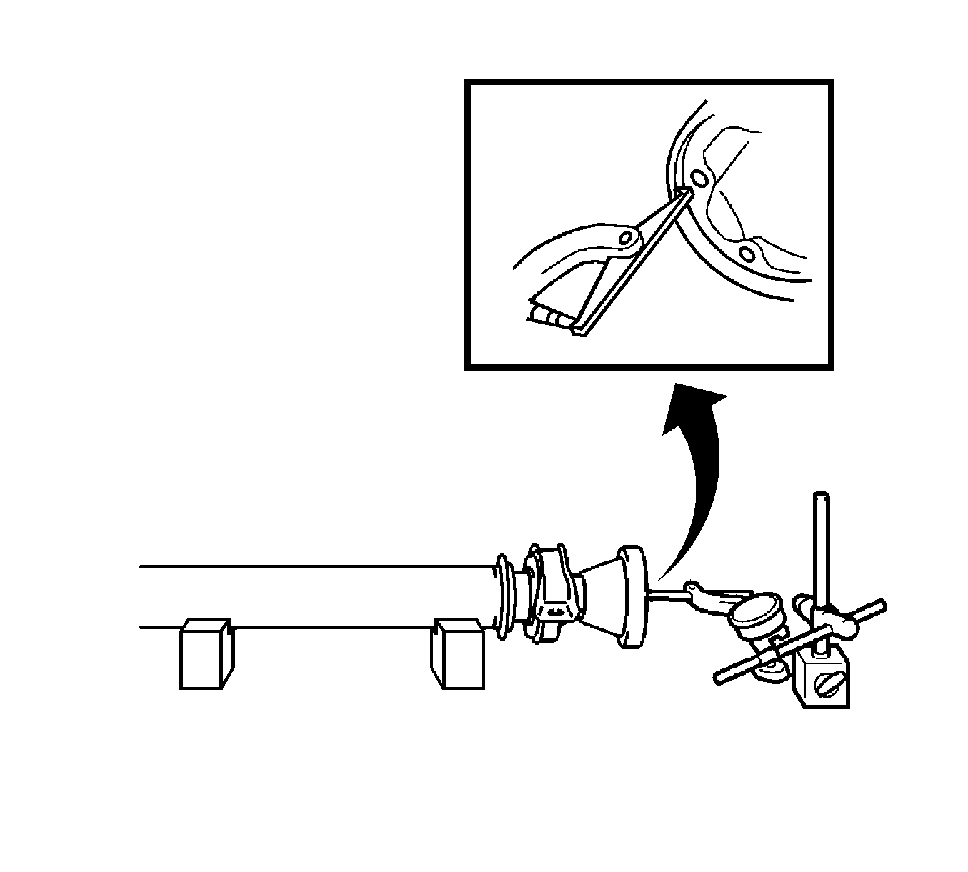
Specification
Maximum runout - 0.1 mm (0.004 in)
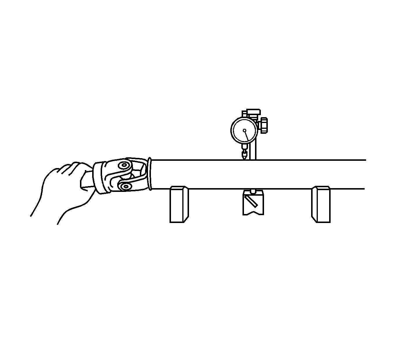
Note: The dial indicator must be set at a right angle to the center of the propeller shaft.
Specification
Maximum runout - 0.4 mm (0.016 in)
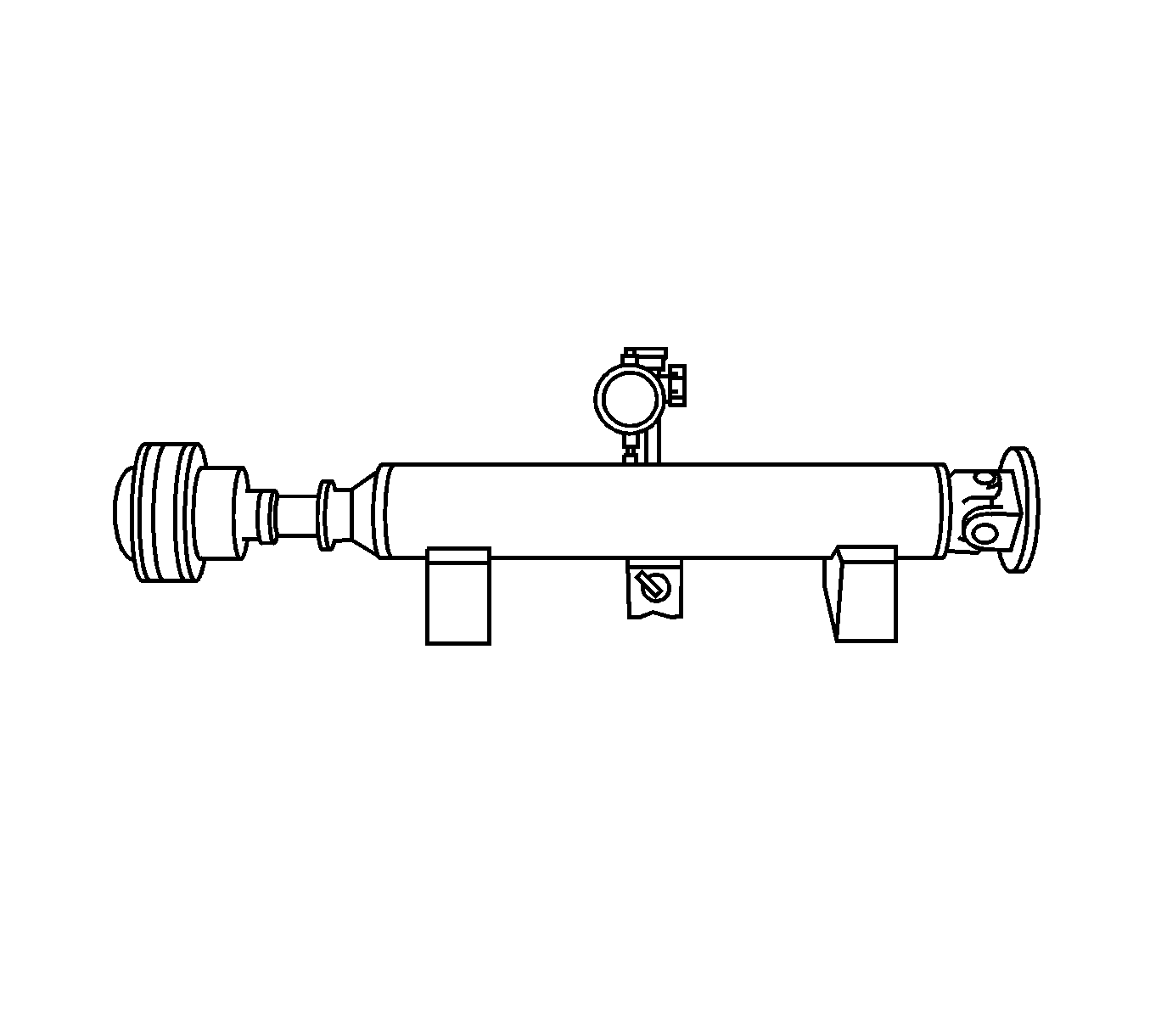
Note: The dial indicator must be set at a right angle to the center of the rear propeller shaft.
Specification
Maximum runout - 0.4 mm (0.016 in)
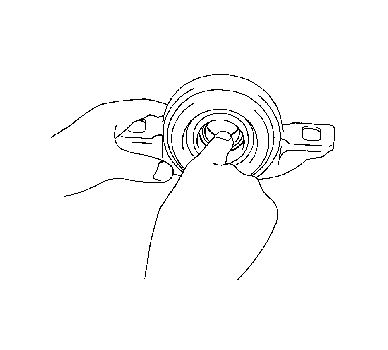
If the No. 1 center support bearing assembly is damaged, worn, or does not turn freely, replace it.
Installation Procedure
- Set the No. 1 center support bearing on the intermediate shaft.
- Install the new washer to the intermediate shaft.
- Align the matchmarks (1) on the universal joint flange and intermediate shaft and place the flange on the shaft.
- Hold the universal joint flange using a suitable tool (1), then press the No. 1 center support bearing assembly into position by tightening down a new nut and washer. Tighten the nut to 182 N·m (134 lb ft).
- Loosen the nut.
- Tighten the nut again to 69 N·m (51 lb ft).
- Using a chisel and a hammer, stake the nut.
- Align the matchmarks (2) on the intermediate shaft and rear propeller shaft, and install the washers and bolts.
- Using a hexagon wrench (6 mm), tighten the bolts with washers temporarily.
- Align the matchmarks (1) on the propeller shaft assembly and the universal joint flange.
- Install the propeller shaft assembly to the front flange with the bolts, washers and nuts. Tighten the bolts and nuts to 74 N·m (55 lb ft).
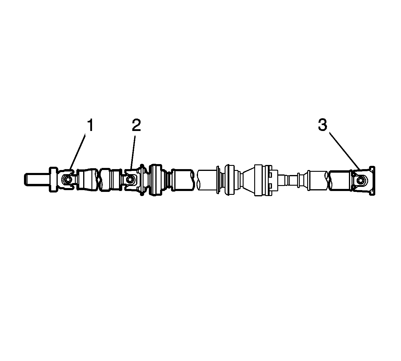
- Check that each joint (1, 2, 3) of the propeller with the center bearing shaft assembly is facing the direction shown in the illustration.
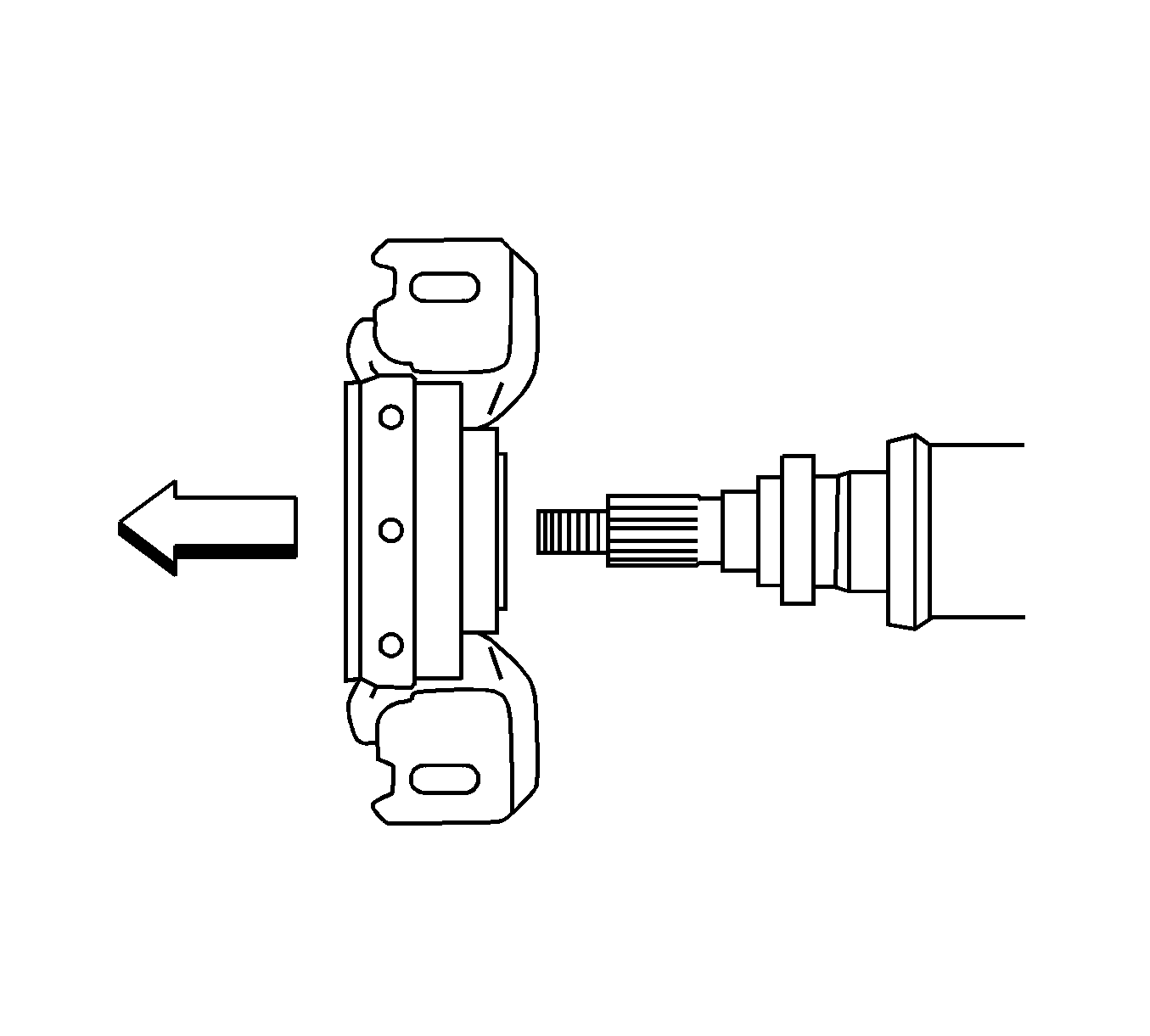
Note: Make sure to install the bearing in the correct position.

Caution: Refer to Fastener Caution in the Preface section.
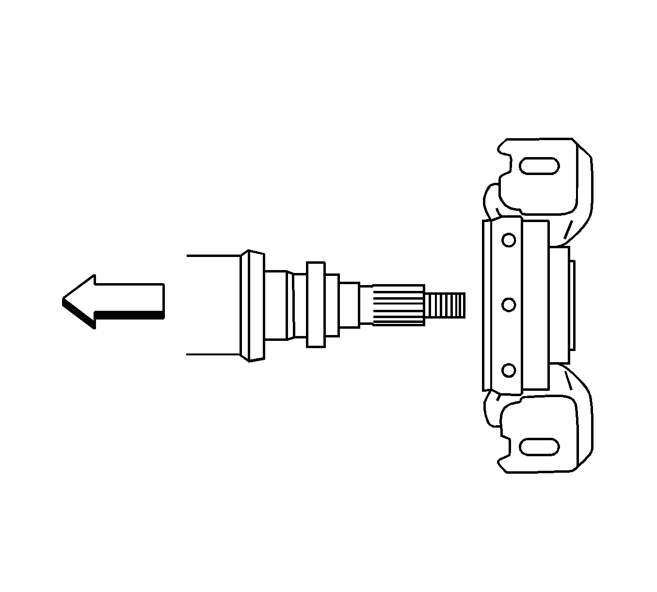
Note: Make sure to install the bearing in the correct position.



Note:
| • | Install the washers between the bolts and the propeller shaft. |
| • | Do not allow grease to adhere to the bolts, washers, or nuts. |
