For 1990-2009 cars only
Stabilizer Shaft Replacement All Wheel Drive and GT
Removal Procedure
- Remove the rear suspension support crossmember in order to access the stabilizer shaft. Refer to Rear Suspension Support Crossmember Replacement.
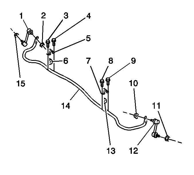
- Use paint in order to place match marks on the stabilizer shaft insulators (6, 13) and on the stabilizer shaft (14).
- Remove the 4 bolts (3, 4, 8, 9).
- Remove the 2 stabilizer shaft insulator brackets (5, 7).
- Remove the 2 stabilizer shaft insulators (6, 13).
- Use a wrench in order to hold each of the stabilizer shaft link studs.
- Remove the 2 nuts (2, 10) from the link studs.
- Remove the stabilizer shaft from the rear suspension support crossmember.

Installation Procedure
- If you are replacing the stabilizer shaft (14) or the insulators (6, 13), copy the match marks from the old components to the new components.
- Position the stabilizer shaft on the rear suspension support crossmember.
- Install the 2 nuts (2, 10) in order to retain the shaft to the link studs. Use a wrench in order to hold each of the link studs.
- Align the match marks and install the insulators to the shaft.
- Install the brackets to the insulators.
- Install the 4 bolts (3, 4, 8, 9) to the brackets.
- Install the rear suspension support crossmember. Refer to Rear Suspension Support Crossmember Replacement.

Caution: Refer to Fastener Caution in the Preface section.
Tighten
Tighten the nuts to 44 N·m (32 lb ft).
Tighten
Tighten the bolts to 18 N·m (13 lb ft).
Stabilizer Shaft Replacement Except All Wheel Drive and GT
Removal Procedure
- Raise and support the vehicle. Refer to Lifting and Jacking the Vehicle.
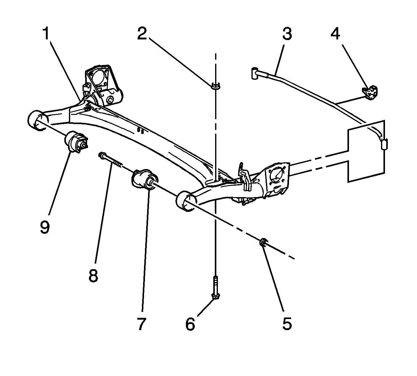
- Remove the insulator (4) from the stabilizer shaft (3).
- Remove the 2 nuts (2).
- Remove the 2 bolts (6).
- Remove the stabilizer shaft from the twist beam rear axle (1).

Installation Procedure
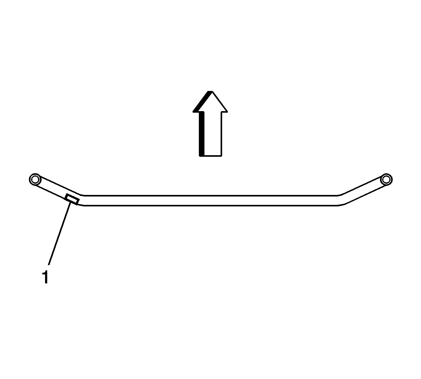
- Position the stabilizer shaft on the rear axle. Ensure the mark (1) is on the left rear of the stabilizer shaft.
- Install the 2 bolts (6) and the 2 nuts (2) in order to retain the stabilizer shaft (3) to the rear axle (1). Hold the bolts with a wrench and tighten the nuts.
- Install the insulator (4) to the center of the stabilizer shaft.
- Lower the vehicle.

Caution: Refer to Fastener Caution in the Preface section.

Tighten
Tighten the nuts to 250 N·m (184 lb ft).
