For 1990-2009 cars only
Shock Absorber Replacement All Wheel Drive and GT
Removal Procedure
- Remove the rear quarter lower trim panel. Refer to Quarter Lower Rear Trim Panel Replacement.
- Raise and support the vehicle. Refer to Lifting and Jacking the Vehicle.
- Remove the rear tire and wheel assembly. Refer to Tire and Wheel Removal and Installation.
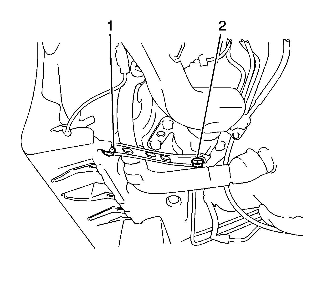
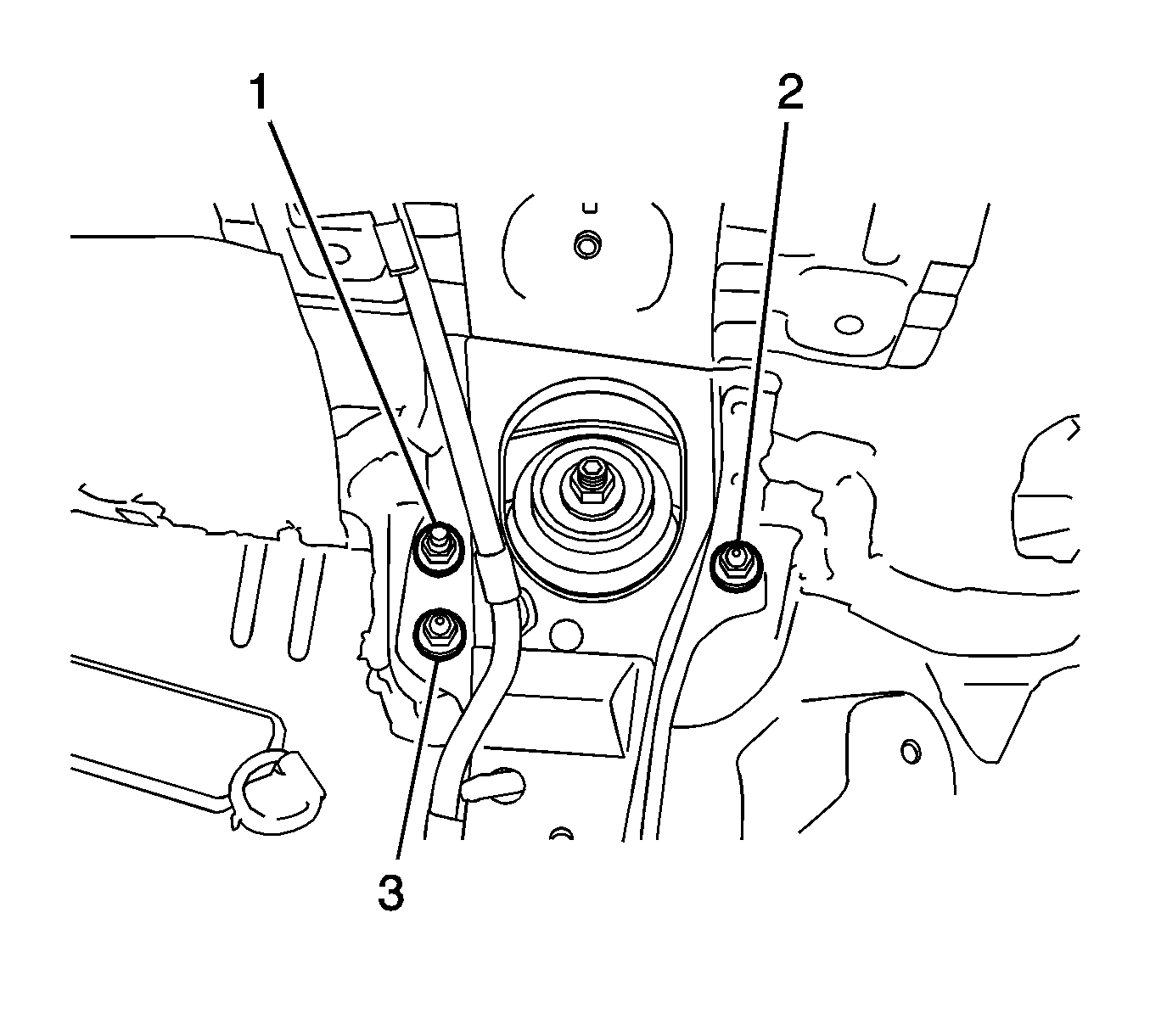
- If you are removing the left rear shock absorber, remove the 2 bolts (1, 2) and the rear floor side member brace.
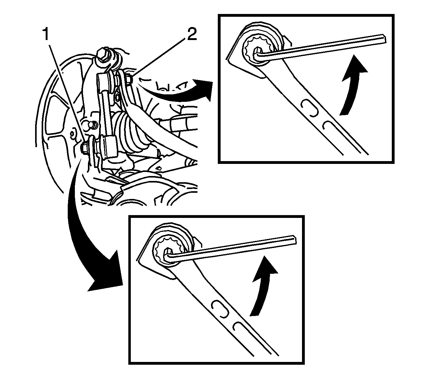
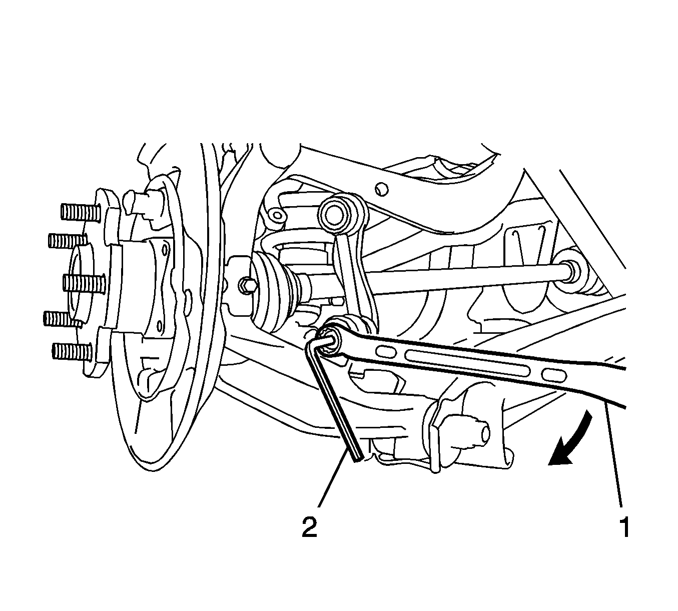
- Use a wrench in order to hold the lower stud on the stabilizer shaft link.
- Remove the nut (1) from the lower stud on the link.
- Separate the link from the control arm.
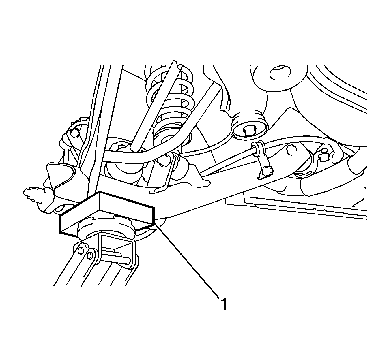
- Use a block of wood (1) and a jack in order to support the lower control arm.
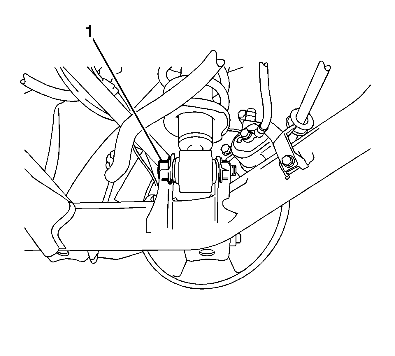
- Remove the nut and the bolt (1) from the shock absorber.
- Separate the shock absorber from the lower control arm.
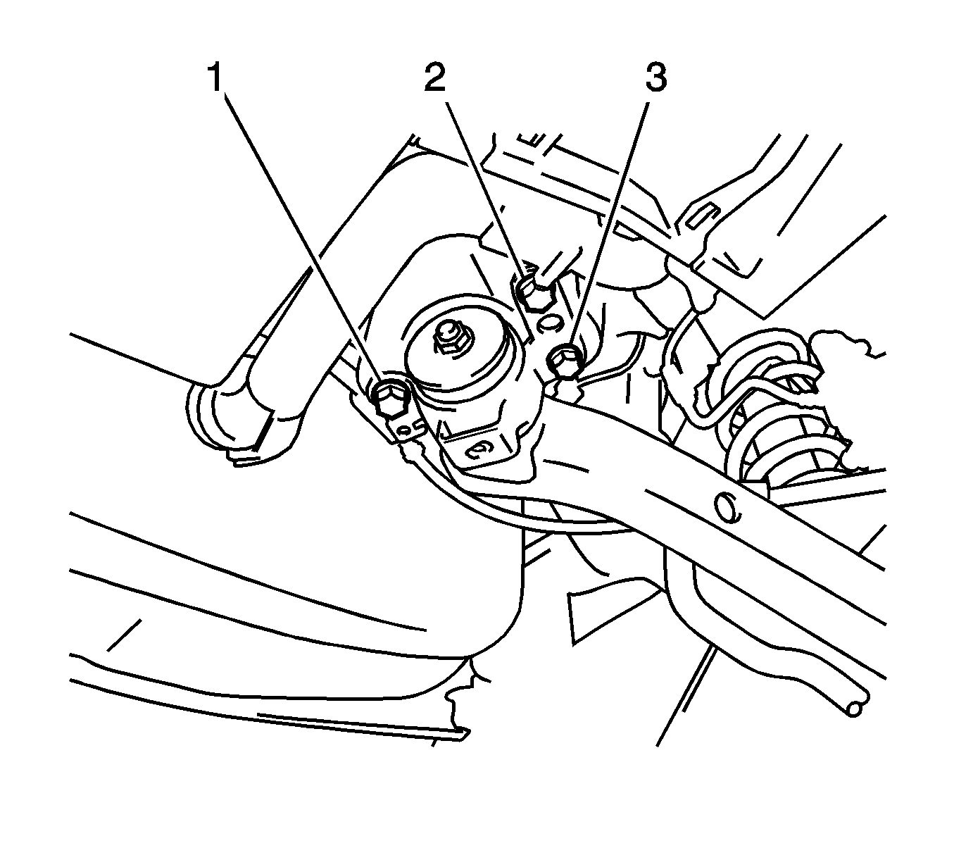
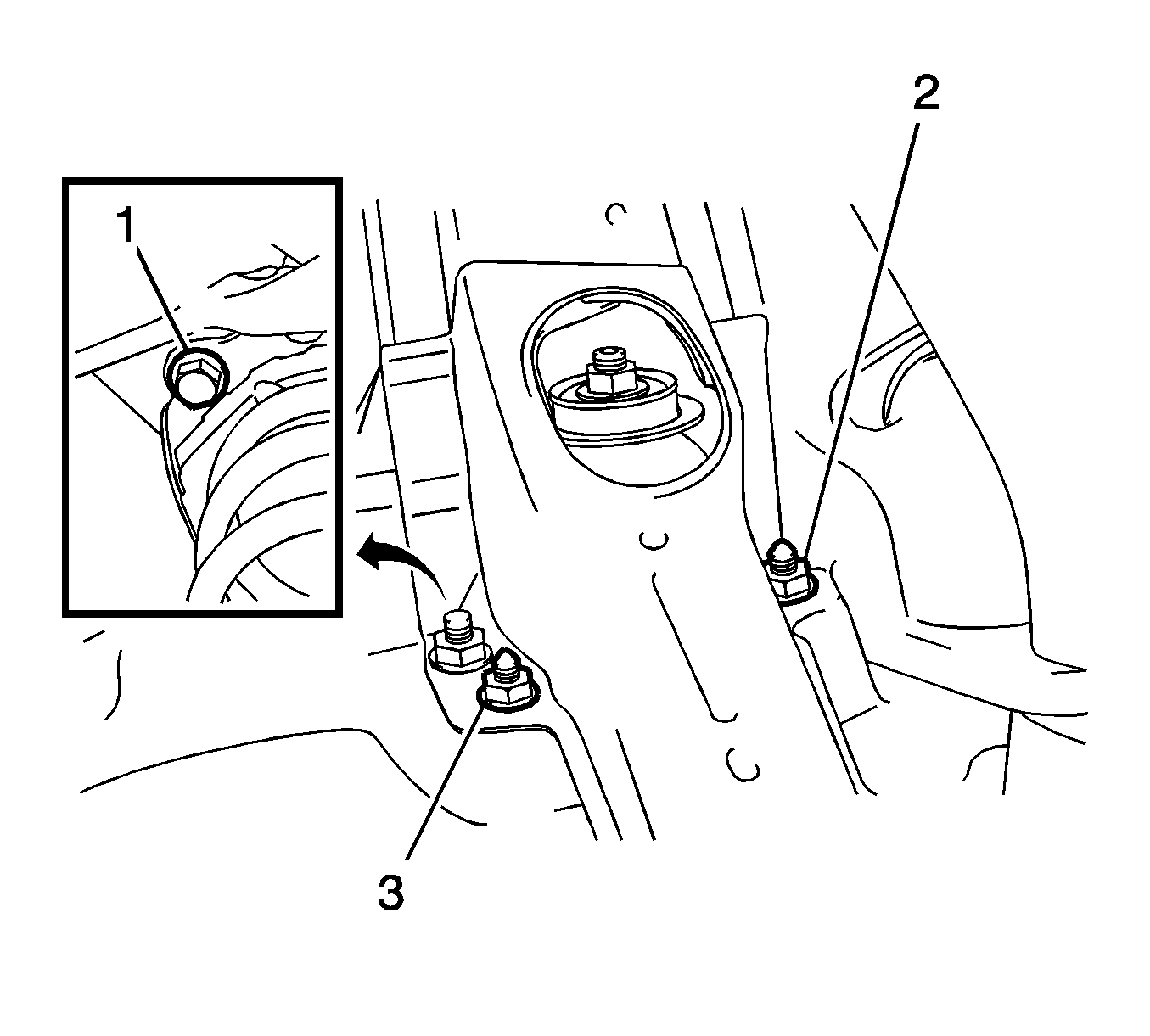
- Remove the 3 nuts (1, 2, 3) from the top mount.
- Remove the 3 bolts (1, 2, 3) from the lower control arm.
- Move the front of the lower control arm down and toward the outside of the vehicle.
- Remove the shock absorber with the coil spring.
- Remove the coil spring, if necessary. Refer to Coil Spring Replacement.
Installation Procedure
- If you removed the coil spring, install the coil spring. Refer to Coil Spring Replacement.
- Install the shock absorber with the 3 nuts (1, 2, 3) and tighten to 80 N·m (59 lb ft).
- Install the shock absorber to the control arm.
- Install, but do not tighten, the bolt (1) and the nut to the shock absorber.
- Install the 3 bolts (1, 2, 3) in order to retain the lower control arm to the body and tighten to 65 N·m (48 lb ft).
- Install the rear floor side member brace with the 2 bolts (1, 2) and tighten to 30 N·m (22 lb ft).
- Install the lower stabilizer shaft link stud to the lower control arm.
- Install the nut to the stud. Use a wrench (2) in order to hold the stud. Tighten the nut to 44 N·m (32 lb ft).
- Remove the jack and the block of wood.
- Install the rear tire and wheel assembly. Refer to Tire and Wheel Removal and Installation.
- Lower the vehicle.
- Install the rear quarter lower trim panel. Refer to Quarter Lower Rear Trim Panel Replacement.
- Raise and support the vehicle on an alignment rack or a lift that places the weight of the vehicle on the tires. Refer to Lifting and Jacking the Vehicle.
- With the weight of the vehicle on the tires, push down on the rear bumper 3 times.
- Tighten the lower shock absorber nut and the bolt (1) to 210 N·m (155 lb ft).
- Measure the wheel alignment. Adjust the wheel alignment if necessary. Refer to Wheel Alignment Measurement.
- Lower the vehicle.
Caution: Refer to Fastener Caution in the Preface section.


Note: Do not tighten the lower shock absorber fasteners. The weight of the vehicle must be on the tire and wheel assemblies before tightening the lower shock absorber fasteners.



Shock Absorber Replacement Except All Wheel Drive and GT
Removal Procedure
- Remove the rear quarter lower trim panel. Refer to Quarter Lower Rear Trim Panel Replacement.
- Raise and support the vehicle. Refer to Lifting and Jacking the Vehicle.
- Remove the rear tire and wheel assembly. Refer to Tire and Wheel Removal and Installation.
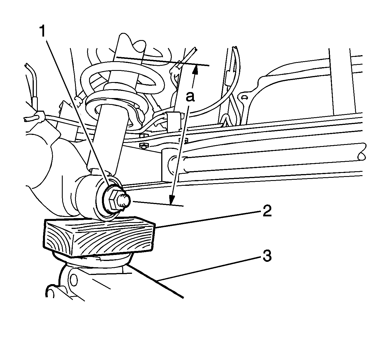
- Use a block of wood (2) and a jack (3) in order to support the rear torsion beam axle.
- Remove the nut and the washer from the shock absorber.
- Remove the 2 nuts (2, 3) from the upper portion of the shock absorber.
- Remove the bolt (1) from the lower portion of the shock absorber.
- Slowly lower the jack and remove the shock absorber with the coil spring.
- Remove the coil spring, if necessary. Refer to Coil Spring Replacement.
Installation Procedure
- If you removed the coil spring, install the coil spring. Refer to Coil Spring Replacement.
- Install the bolt (1) to the lower portion of the shock absorber.
- Install the 2 nuts (2, 3) to the upper portion of the shock absorber.
- Use a block of wood (2) and a jack (3) in order to support the rear torsion beam axle.
- Install the washer (1) to the lower portion of the shock absorber.
- Install, but do not tighten, the nut to the lower portion of the shock absorber.
- Remove the jack and the block of wood.
- Install the rear tire and wheel assembly. Refer to Tire and Wheel Removal and Installation.
- Lower the vehicle.
- Install the rear quarter lower trim panel. Refer to Quarter Lower Rear Trim Panel Replacement.
- With the weight of the vehicle on the tires, push down on the rear bumper 3 times.
- Ensure the shock absorbers and the coil springs are compressed to the specification. If necessary, use a block of wood and a jack in order to raise the axle. If necessary, add weight, or even an assistant, to the rear seat.
- Tighten the lower shock absorber nut.
- Lower the jack.
- Measure the wheel alignment and perform the zero point calibrations. Refer to Wheel Alignment Measurement.
- Lower the vehicle.
Caution: Refer to Fastener Caution in the Preface section.

Tighten
Tighten the bolt to 80 N·m (59 lb ft).
Tighten
Tighten the nuts to 80 N·m (59 lb ft).

Note: Do not tighten the lower shock absorber fasteners yet. The weight of the vehicle must be on the tire and wheel assemblies before tightening the lower shock absorber fasteners.
Specification
The distance (a) is 206 mm (8.11 in).
Tighten
Tighten the nut to 80 N·m (59 lb ft).
