Special Tools
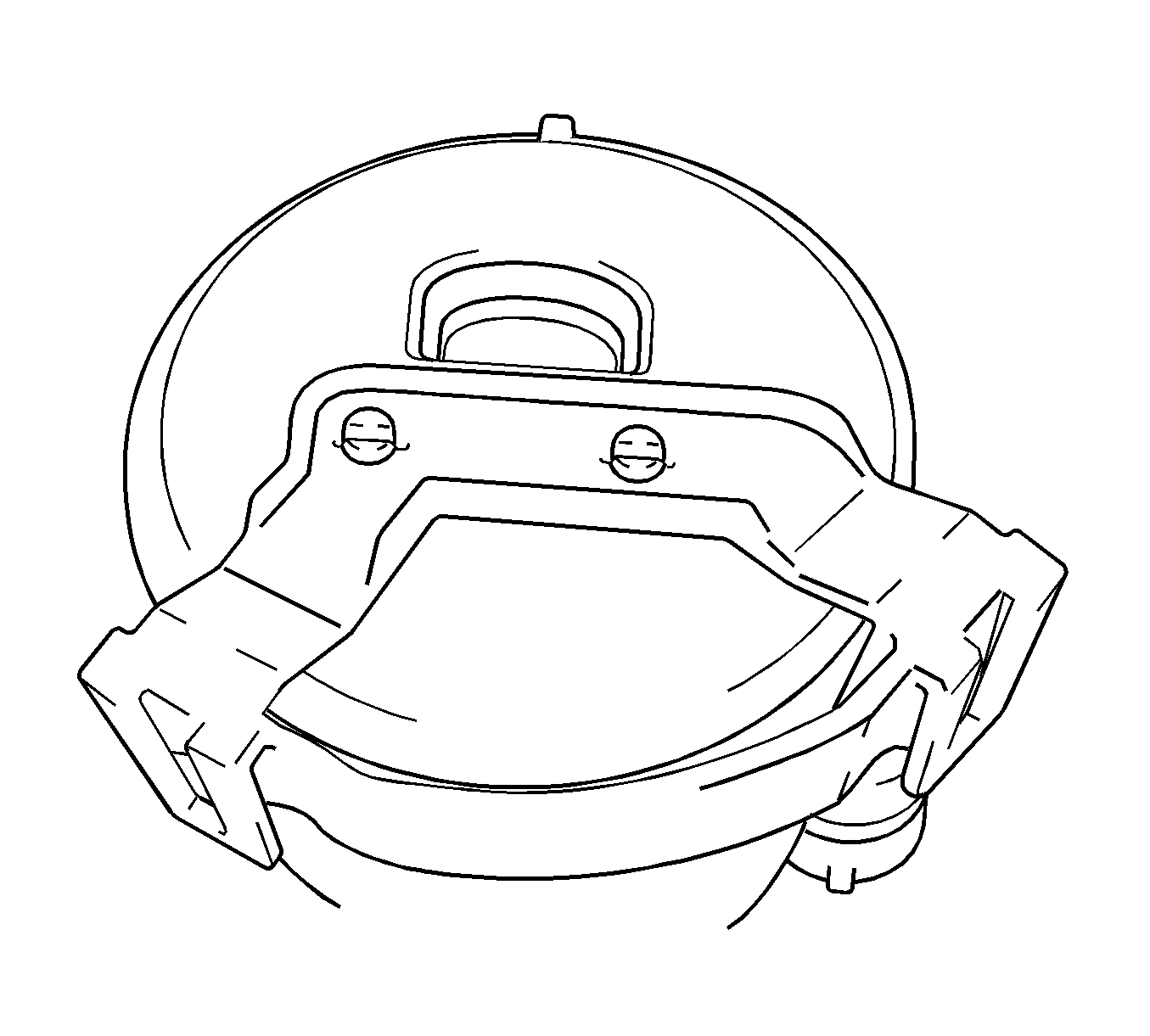
CH-47717 Fuel Lock Ring Remover Tool
Removal Procedure
- Remove the rear seat cushion assembly. Refer to Rear Seat Cushion Replacement.
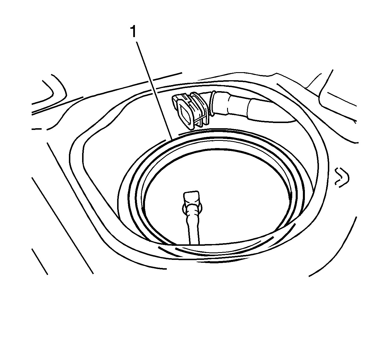
- Remove the rear floor service hole cover (1).
- Disconnect the connector from the fuel suction tube assembly.
- Discharge the fuel system pressure. Refer to Fuel Pressure Relief.
- Start the engine. After the engine stops naturally, turn the ignition switch off.
- Crank the engine again and make sure that the engine does not start.
- Remove the fuel tank cap to relieve any pressure from the fuel tank.
- Disconnect the cable from the negative battery terminal.
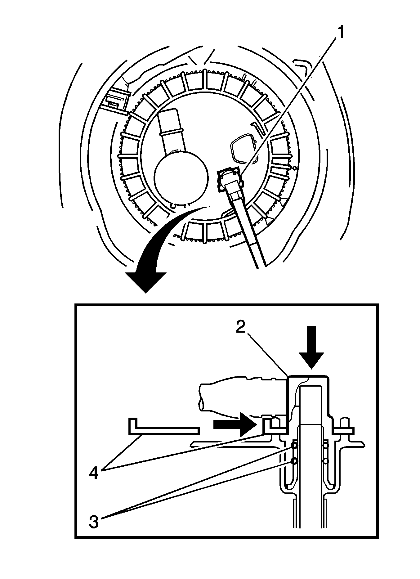
- Remove the tube joint clip (2), then pull the fuel tube joint out of the plug of the fuel suction tube assembly (1).
- Disconnect the fuel tank vent hose.
- Pinch the retainer and pull the fuel tank vent connector out of the fuel tank to disconnect the fuel tank vent hose from the fuel suction plate.
- Using the CH-47717 remover tool , loosen the fuel pump gage retainer.
- Remove the fuel pump gage retainer while holding the fuel suction tube assembly by hand.
- Remove the fuel suction with pump and tube assembly.
- Remove the fuel pump assembly (1) from the fuel tank.

Warning: Refer to Battery Disconnect Warning in the Preface section.
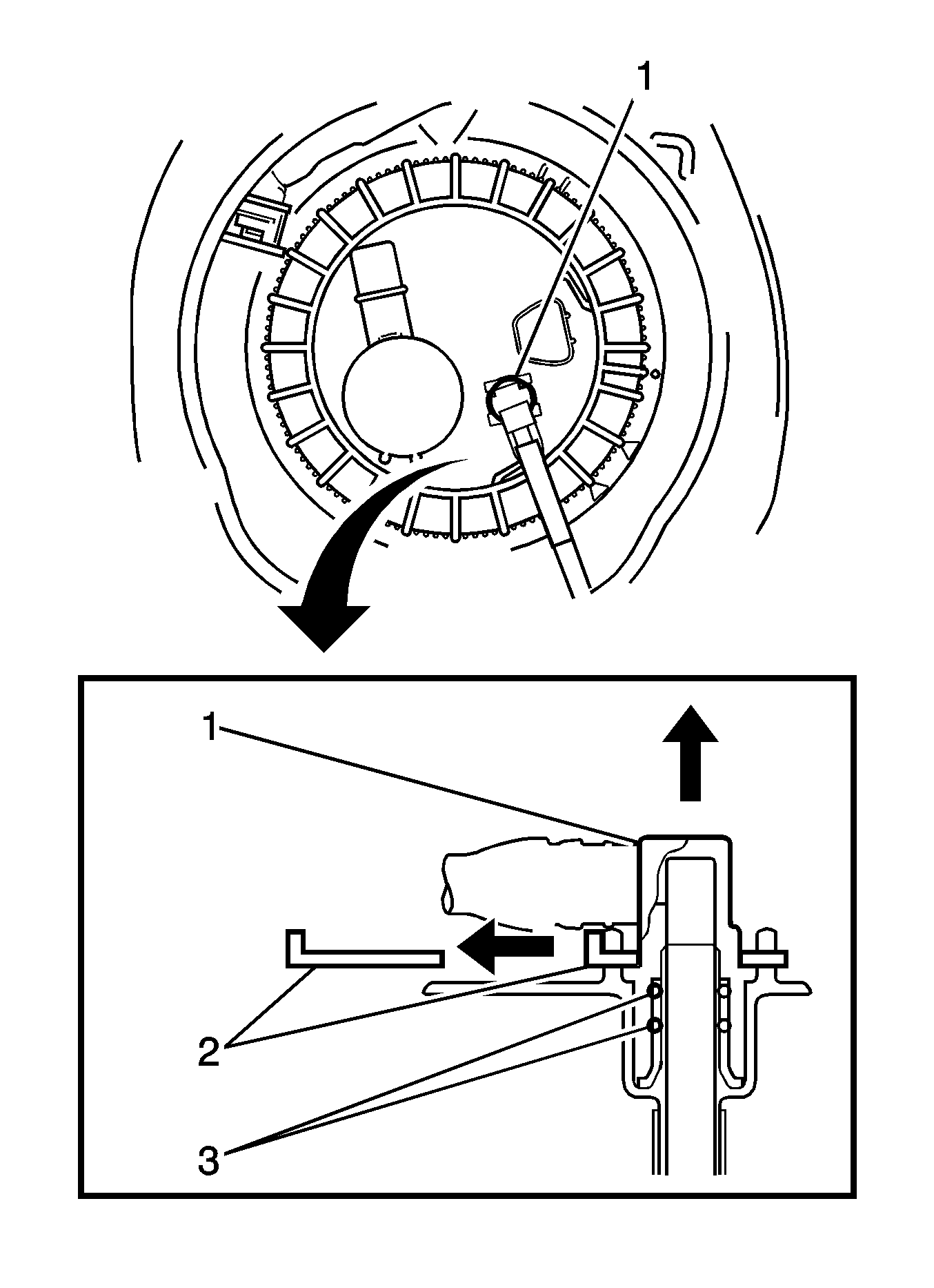
Note: Check that there is no dirt or other foreign objects around the fuel tube joint before disconnecting it. Clean the joint if necessary. It is necessary to prevent mud or dirt from entering the joint. If mud or dirt gets in the joint, the O-rings may not seal properly. Only disconnect the joint by hand. Do not bend, kink or twist the nylon tubes. Protect the contact surfaces by covering it with a plastic bag.
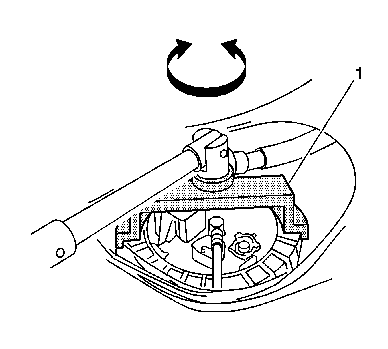
Note: Do not use any tools other than specified in this operation. Damage to the fuel pump gage retainer or the fuel tank may result. Loosen the retainer by turning it counterclockwise while holding the CH-47717 remover tool down. Do not allow the claw of the tank suction tube support to slip out of its groove on the fuel tank.
Note: The ribs on the fuel pump gage retainer can be fitted into the tips of the CH-47717 remover tool (1).
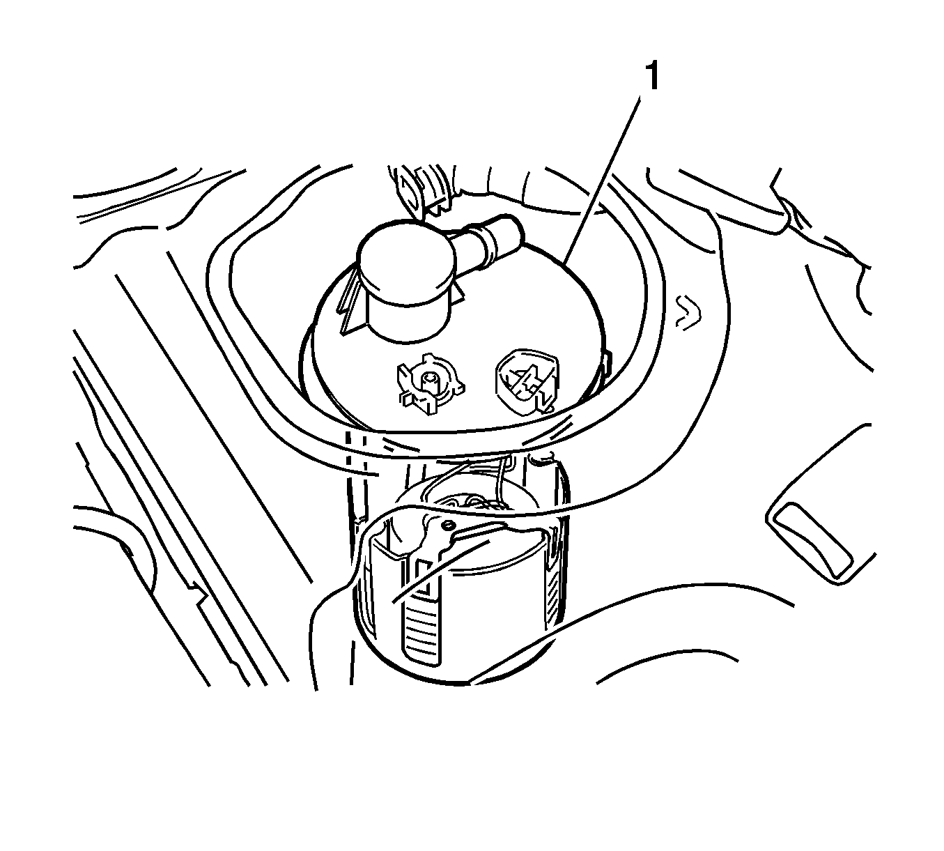
Disassembly Procedure
- Remove the gasket (1) from the fuel tank.
- Remove the fuel sender gage assembly. Refer to Fuel Sender Assembly Replacement.
- Release the claw and disconnect the fuel pump filter hose (1) and remove the fuel pump.
- Remove the E-ring (2) and separate the 2 claws, then remove the fuel pump sub-tank.
- Disconnect the fuel pump harness connector (1).
- Using a screwdriver with its tip wrapped in protective tape, disengage the 2 claws and remove the No. 1 fuel suction support.
- Using a screwdriver with its tip wrapped in protective tape, disengage the 5 claws, and remove the fuel pump filter and fuel pump form the fuel filter.
- Disconnect the fuel pump harness connector (1).
- Remove the O-ring (1) from the fuel pump.


Note: Do not separate the tube (4) indicated in the illustration.


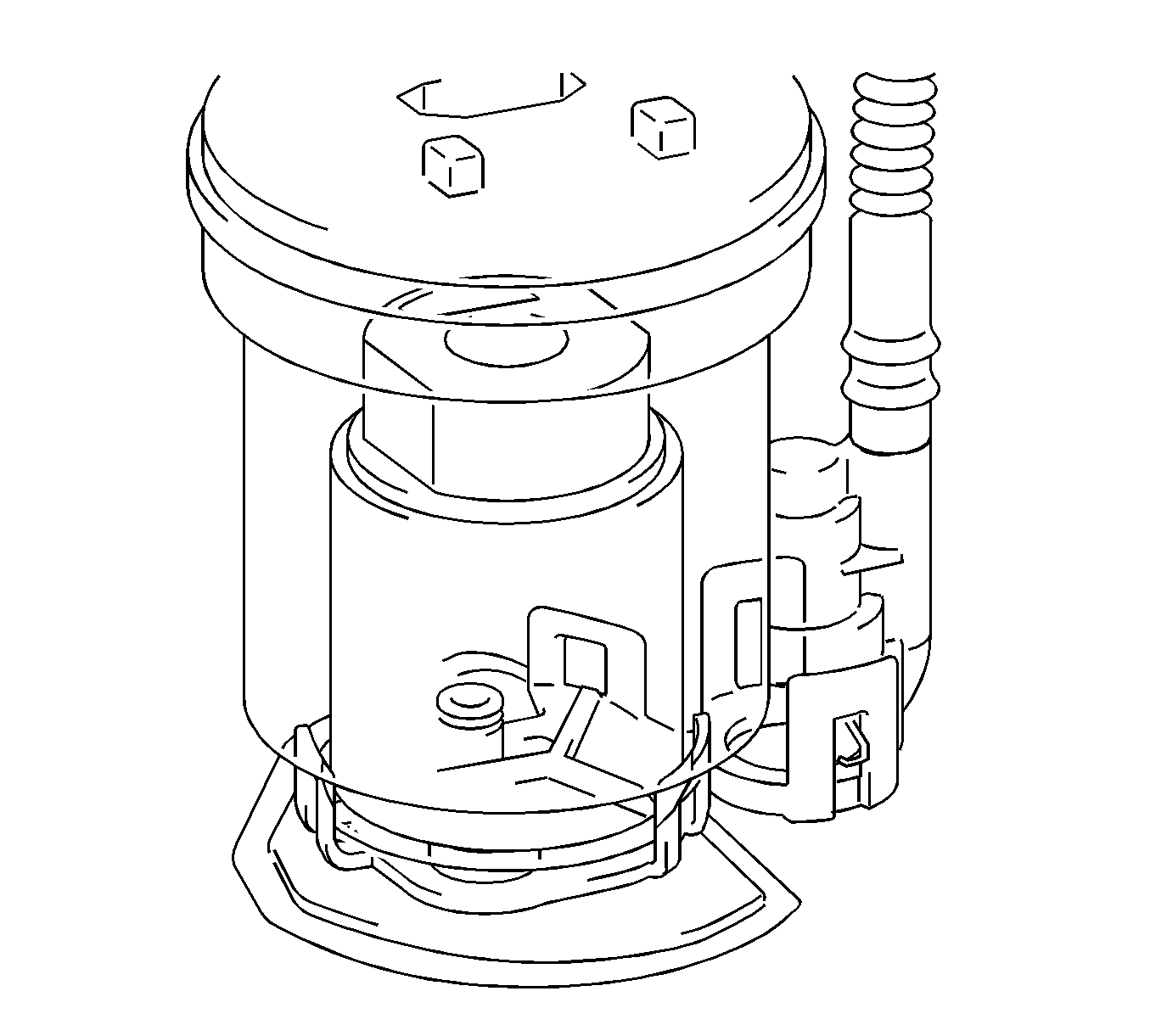
Note: Do not remove the suction filter. Do not use either the fuel pump or the suction filter if the suction filter is removed from the fuel pump.


Reassembly Procedure
- Apply a light coat of oil to a new O-ring (1), then install it into the fuel pump.
- Connect the fuel pump harness connector (1).
- Apply a light coat of oil to the O-ring of the fuel pump again.
- Engage the 5 claws, and install the fuel pump filter onto the fuel filter.
- Engage the 2 claws of the No. 1 fuel suction support.
- Connect the fuel pump harness connector (1).
- Engage the 2 claws and install the E-ring (2) and fuel pump sub-tank.
- Align the groove of the fuel pump filter hose with the cutout of the fuel sub-tank and install the hose.
- Connect the connector of the fuel pump harness (1).
- Install the fuel sender gage assembly. Refer to Fuel Sender Assembly Replacement.

Note: Do not disassemble the fuel pump and the suction filter because they are non-reusable parts.


Note: Make sure that the O-ring is not cracked or jammed when installing.


Note: Do not apply excessive force to the fuel tube or the suction support.
Installation Procedure
- Install the fuel suction tube assembly.
- Install a new gasket (1) onto the fuel tank.
- Set the fuel suction tube to the fuel tank.
- Install the fuel pump gage retainer.
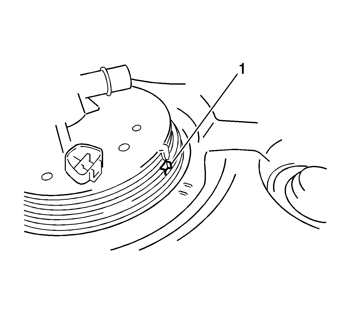
- Align the protrusion (1) of the fuel suction tube with the notch of the fuel tank.
- While holding the fuel suction tube assembly by hand to prevent it from tilting, align the starting marks (1) on the fuel pump gage retainer and fuel tank and tighten the fuel pump gage retainer.
- Using CH-47717 remover tool and your hand, tighten the fuel pump gage retainer 2 revolutions so that the mark of the retainer comes within the range shown in the illustration.
- Connect the fuel tank vent hose.
- Align the fuel tank vent connector with the pipe, then push in the fuel tank vent connector until the retainer makes a "click" sound to connect the fuel tank vent hose to the fuel suction plate.
- Connect the fuel tank main tube (1).
- Push the fuel tube joint (2) in the plug of the fuel suction plate, then install the tube joint clip (4).
- Connect the cable to the negative battery terminal.
- Inspect for a fuel leak.
- Connect the fuel pump connector (2).
- Install the rear floor service hole cover.
- Install the rear seat cushion assembly. Refer to Rear Seat Cushion Replacement.
Note: Make sure that the fuel sender gauge arm does not bend.

Note:
• Use
CH-47717 remover tool
only. Do not use any other tools such as a screwdriver. • Insert the notch of
CH-47717 remover tool
into the rib of the fuel pump gage retainer.

Note: Check that there are no scratches or foreign objects around the connecting surfaces of the fuel tank vent connector and pipe before performing this work. After connecting the fuel tank vent hose, check that the fuel tank vent hose is securely connected by pulling on the quick connector.
Warning: Refer to Battery Disconnect Warning in the Preface section.

