For 1990-2009 cars only
| Table 1: | Valve Seat Width |
Special Tools
EN 49184 Valve Guide Bushing Replacer
Valve Guide Replacement Procedure
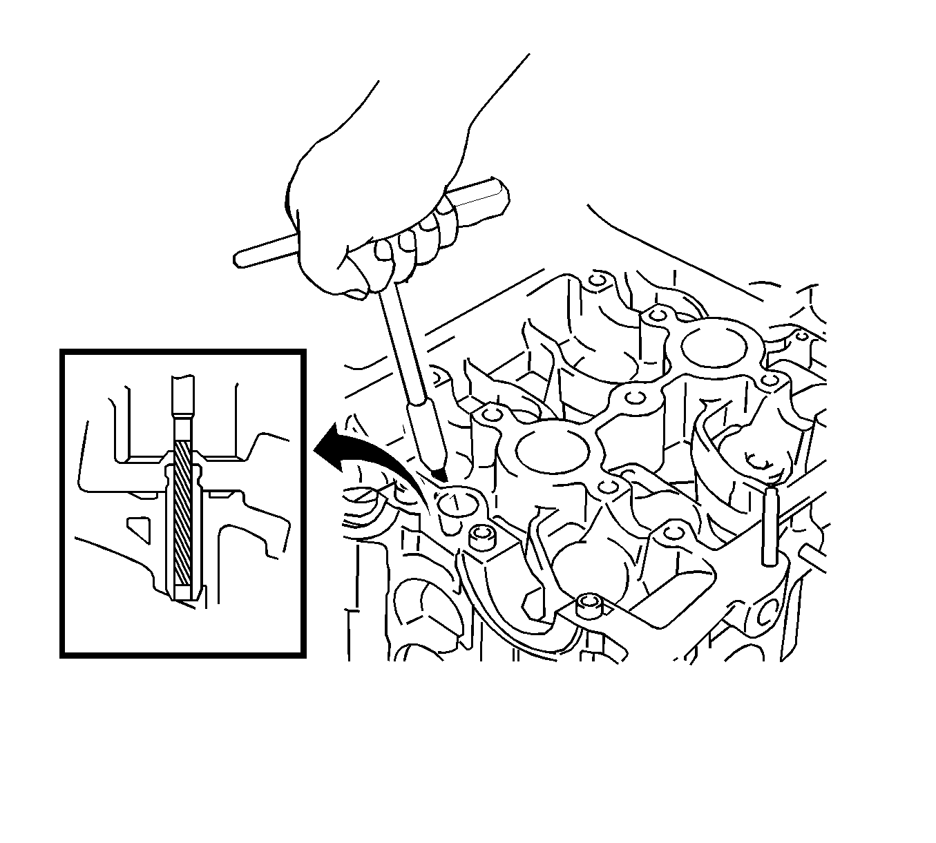
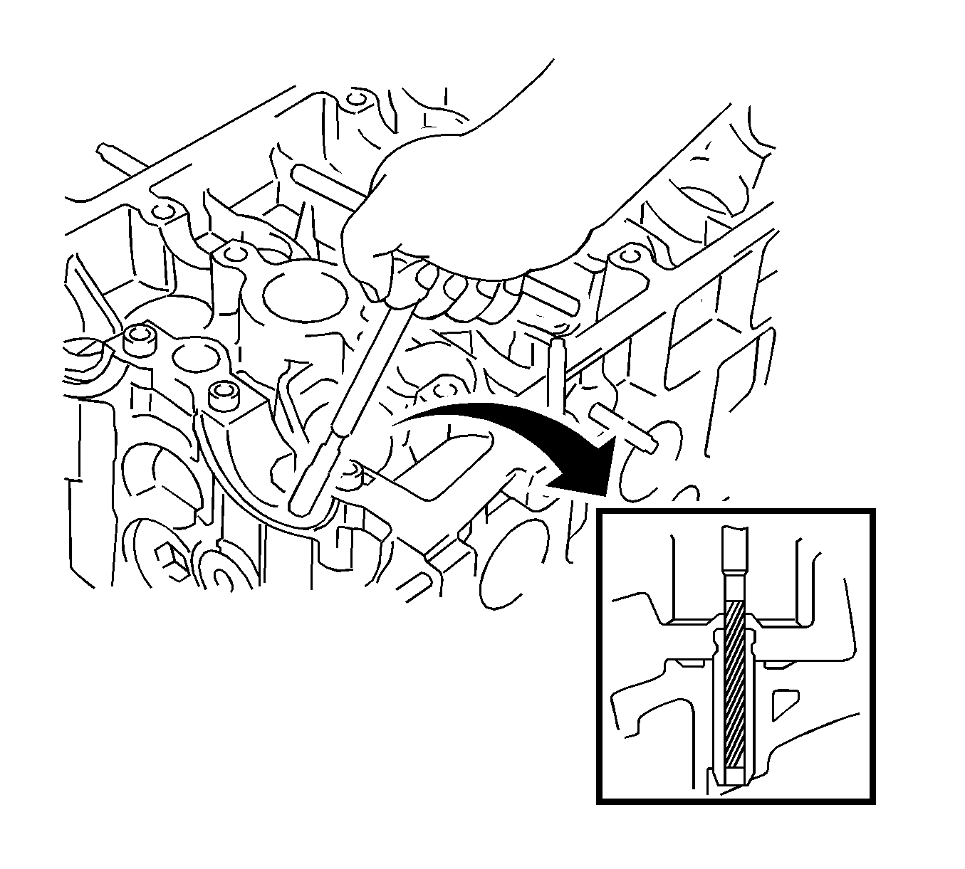
- Remove intake valve guide bush.
- Heat the cylinder head to 80 to 100°C (176 to 212°F).
- Place the cylinder head on wooden blocks.
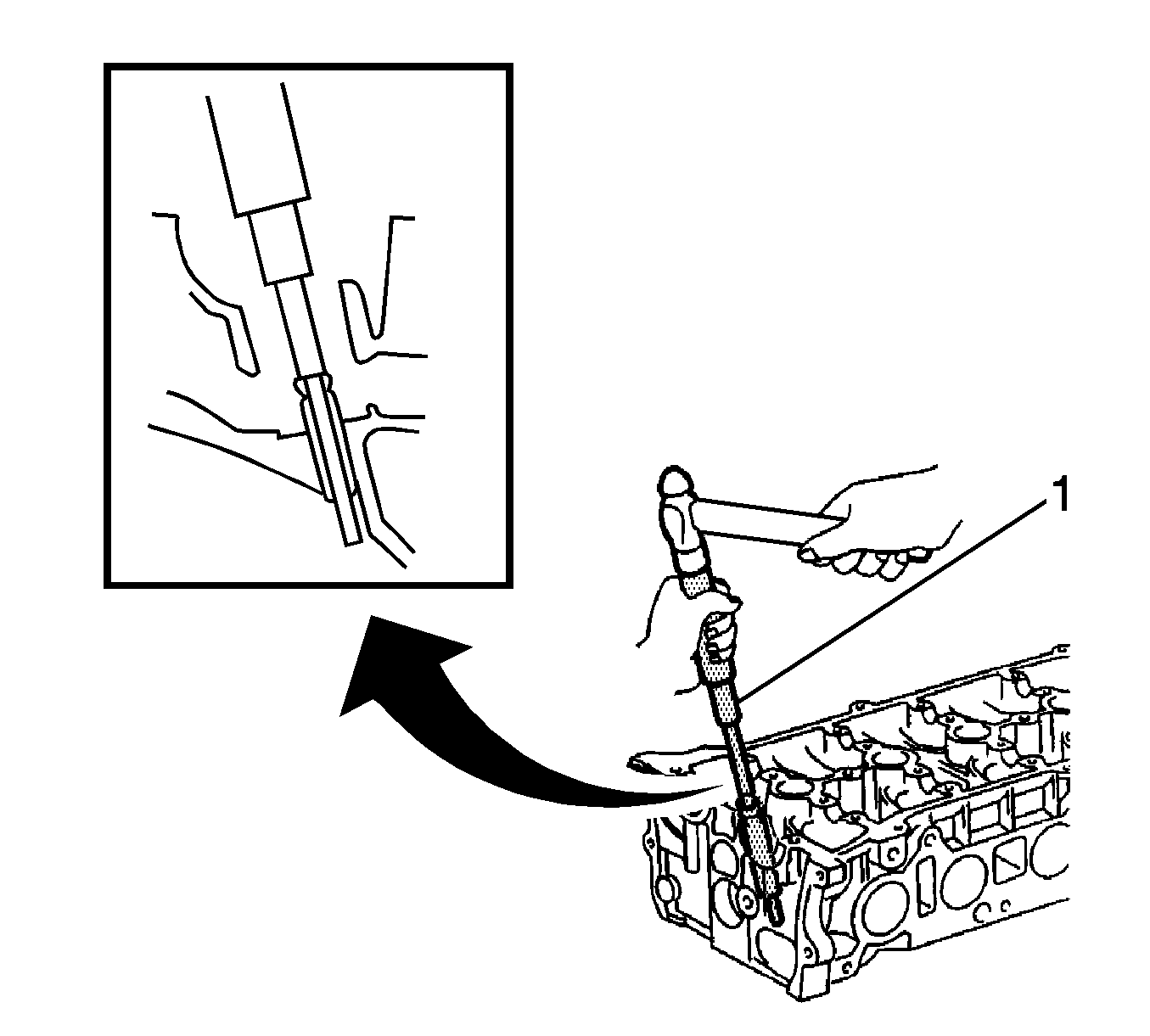
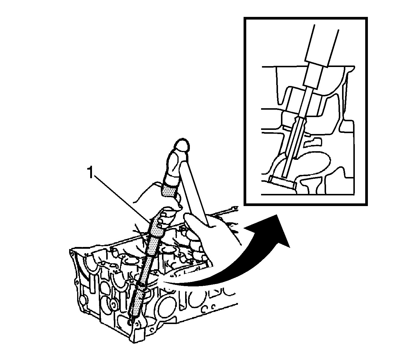
- Using EN 49184 replacer (1) and a hammer, tap out the guide bush.
- Heat the cylinder head to 80 to 100°C (176 to 212 °F).
- Place the cylinder head on wooden blocks.
- Using EN 49184 replacer (1) and a hammer, tap out the guide bush.
- Using a caliper gauge, measure the bush bore diameter of the cylinder head.
- If the cylinder head bush bore diameter is greater than 10.306 mm (0.4057 in), machine the bush bore to a dimension of 10.335 to 10.356 mm (0.4069 to 0.4077 in) and install an O/S 0.05 valve guide bush. If the bush bore diameter of the cylinder head is greater than 10.356 mm (0.4077 in), replace the cylinder head.
- Heat the cylinder head to 80 to 100°C (176 to 212°F).
- Place the cylinder head on wooden blocks.
- Using EN 49184 replacer (2) and a hammer, tap in a new guide bush to the specified protrusion height.
- Using a sharp 5.5 mm reamer, ream the guide bush to obtain the standard specified clearance between the guide bush and valve stem.
- Install exhaust valve guide bush.
- Using a caliper gauge, measure the bush bore diameter of the cylinder head.
- If the cylinder head bush bore diameter is greater than 10.306 mm (0.4057 in), machine the bush bore to a dimension of 10.335 to 10.356 mm (0.4069 to 0.4077 in) and install an O/S 0.05 valve guide bush. If the bush bore diameter of the cylinder head is greater than 10.356 mm (0.4077 in), replace the cylinder head.
- Heat the cylinder head to 80 to 100°C (176 to 212°F).
- Place the cylinder head on wooden blocks.
- Using EN 49184 replacer (1) and a hammer, tap in a new guide bush to the specified protrusion height.
- Using a sharp 5.5 mm reamer, ream the guide bush to obtain the standard specified clearance between the guide bush and valve stem.
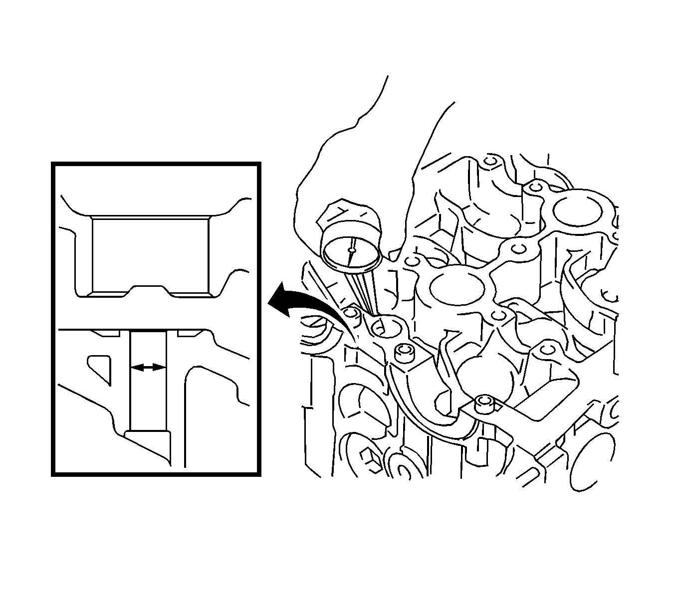
Cylinder Bore Diameter
10.285 to 10.306 mm (0.4049 to 0.4057 in)
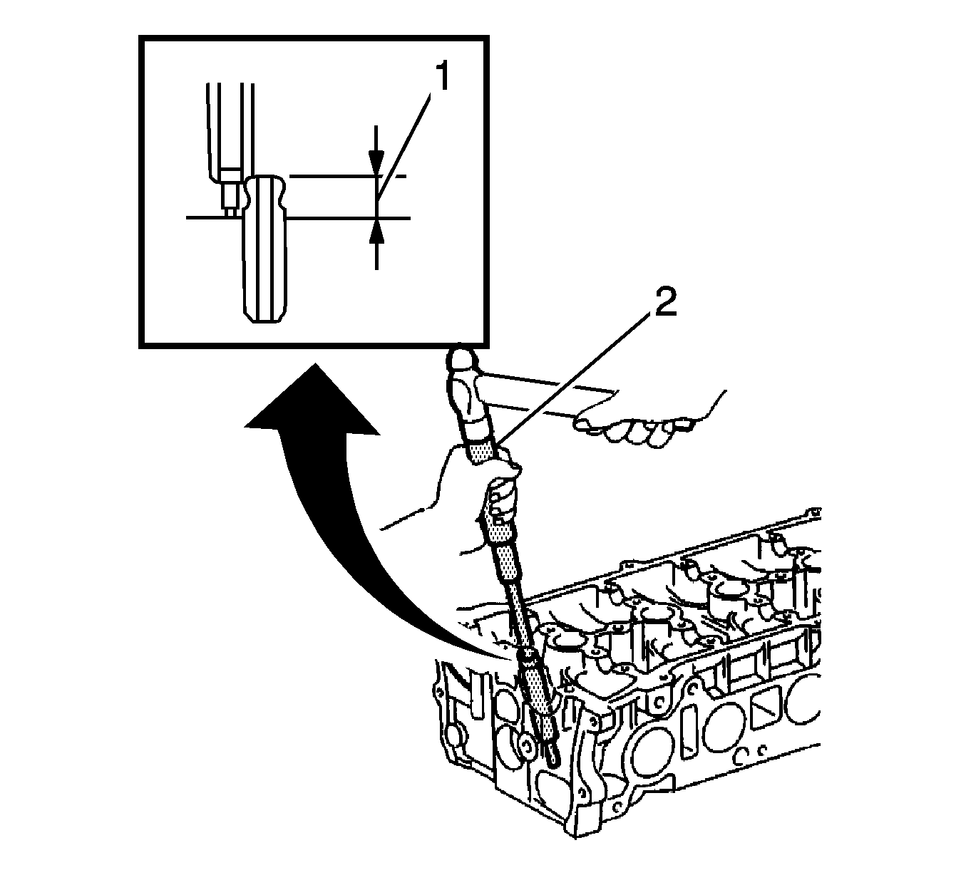
Protrusion Height
9.6 to 10.0 mm (0.3779 to 0.3937 in)
Standard Oil Clearance
0.025 to 0.060 mm (0.0010 to 0.0024 in)
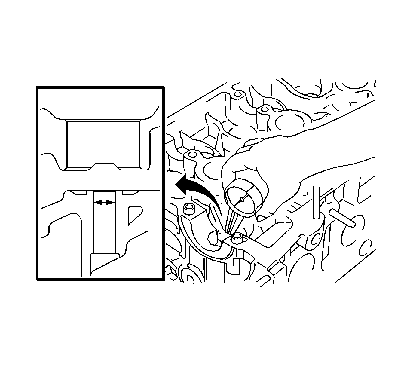
Cylinder Bore Diameter
10.285 to 10.306 mm (0.4049 to 0.4057 in)
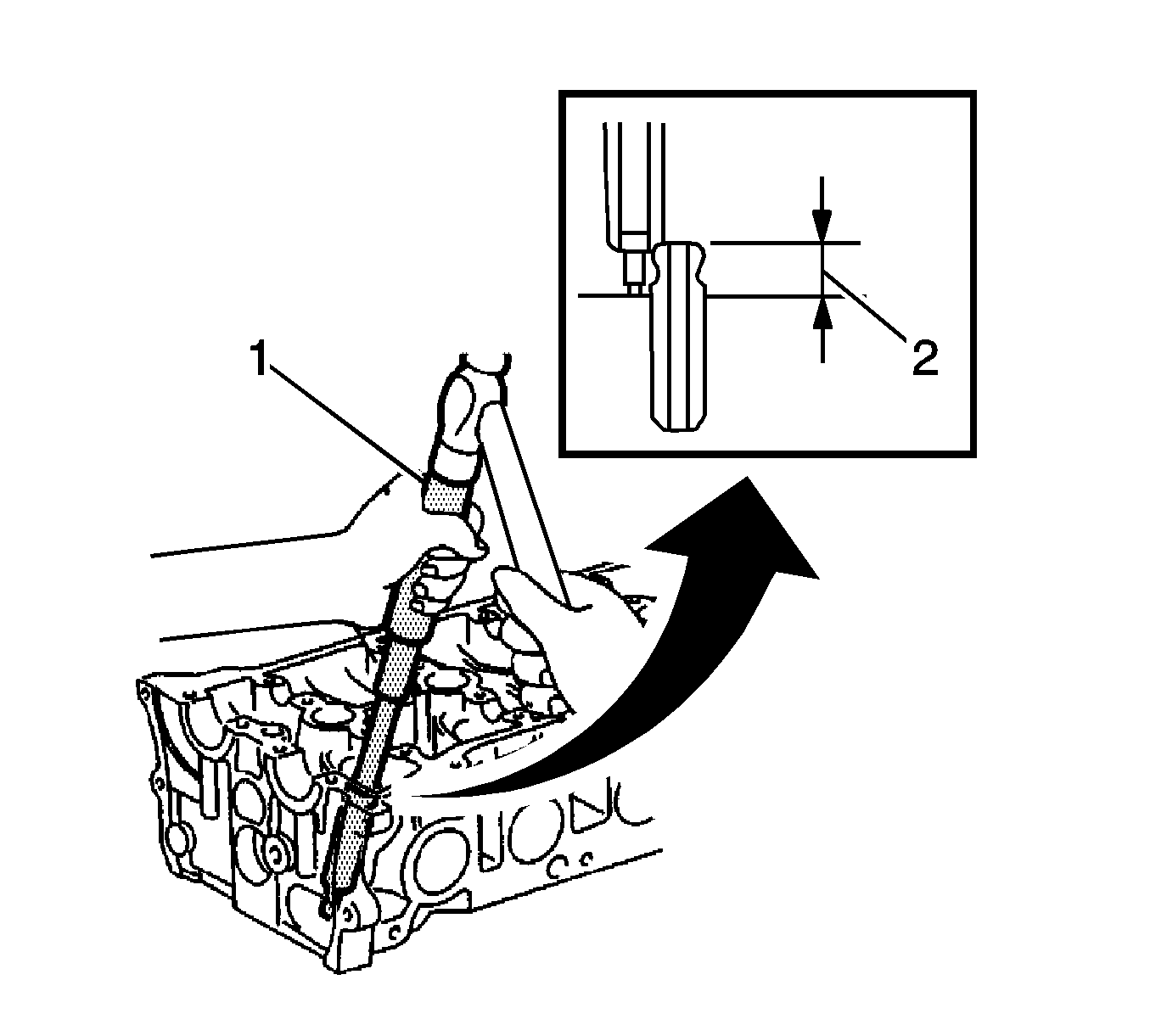
Protrusion Height
9.6 to 10.0 mm (0.3779 to 0.3937 in)
Standard Oil Clearance
0.030 to 0.060 mm (0.0012 to 0.0024 in)
Bush size | Bush bore diameter |
|---|---|
Use STD | 10.285 to 10.306 mm (0.4049 to 0.4057 in) |
Use O/S 0.05 | 10.335 to 10.356 mm (0.4069 to 0.4077 in) |
Valve and Valve Seat Repair Procedure
- Apply a light coat of prussian blue to the valve face.
- Lightly press the valve face against the valve seat.
- Check the valve face and valve seat according to the following procedure:
- Using a 45° cutter, resurface the valve seat so that the valve seat width is more than the specification.
- Using 30° to 75° cutters, correct the valve seat so that the valve contacts the entire circumference of the seat. The contact should be in the center of the valve seat, and the valve seat width should be maintained within the specified range around the entire circumference of the seat.
- Handrub the valve and valve seat with an abrasive compound.
- Check the valve seating position.
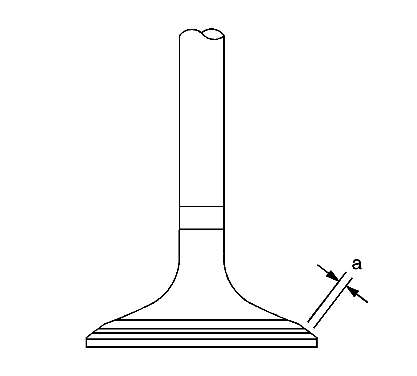
| 3.1. | If prussian blue appears 360° around the valve face, the valve face is concentric. If not, replace valve. |
| 3.2. | If prussian blue appears 360° around the valve seat, the guide and valve face are concentric. If not, resurface the valve seat. |
| 3.3. | Check that the valve seat contact is in the middle of the valve face with the width between 1.0 to 1.4 mm (intake side (0.039 to 0.055 in)). |
| 3.4. | Check that the valve face width is between 1.2 to 1.6 mm (Exhaust side (0.047 to 0.063 in)). |
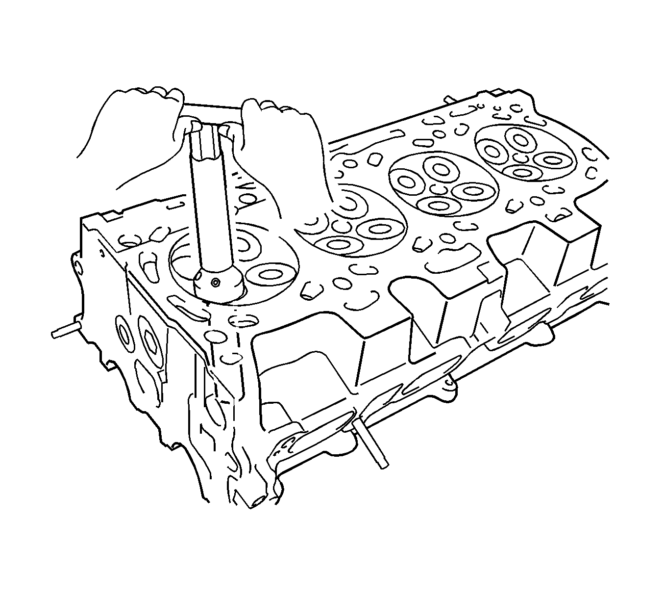
Note: Repair the seat while checking the seating position. Keep the lip free from foreign matter.
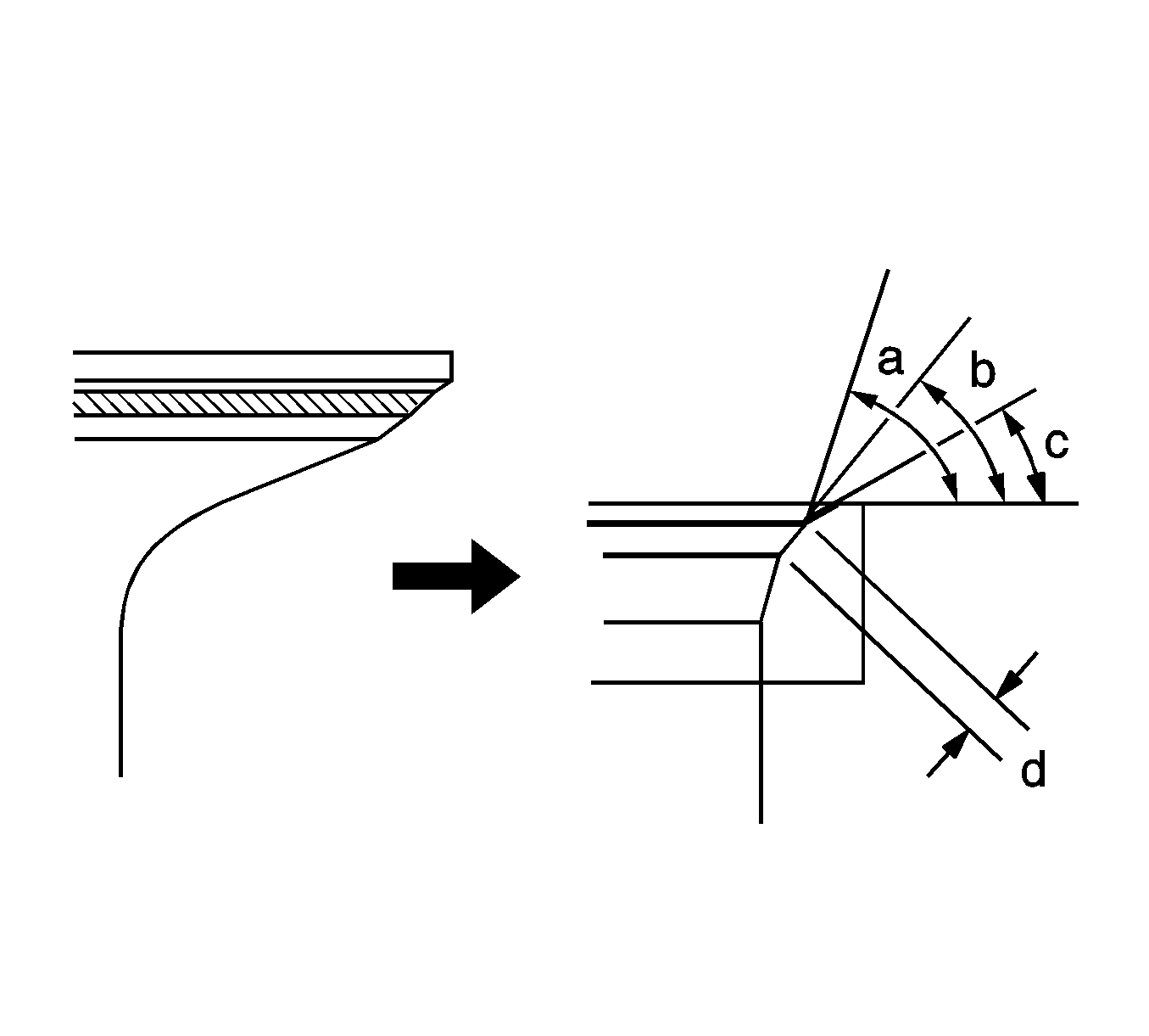
Item | Specified Condition |
|---|---|
Intake Side | 1.0 to 1.4 mm (0.039 to 0.055 in) |
Exhaust Side | 1.2 to 1.6 mm (0.047 to 0.063 in) |
