- Install the valve lash adjuster assembly.
- Place the lash adjuster into a container filled with engine oil.
- Install the lash adjusters.
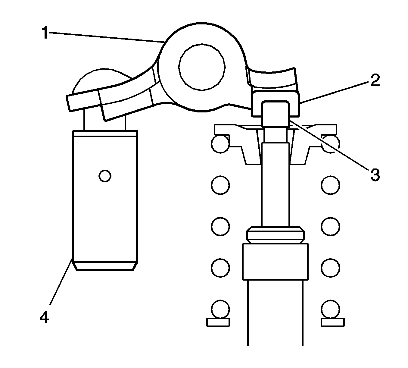
- Install the valve rocker arm subassembly
- Apply engine oil to the lash adjuster tip and valve stem cap end.
- Make sure that the valve rocker arms (1) are installed properly.
- Clean both surfaces of the bearings.
- Install the 2 camshaft bearings.
- Using vernier calipers, measure the distance between the bearing cap edge and the camshaft bearing edge.
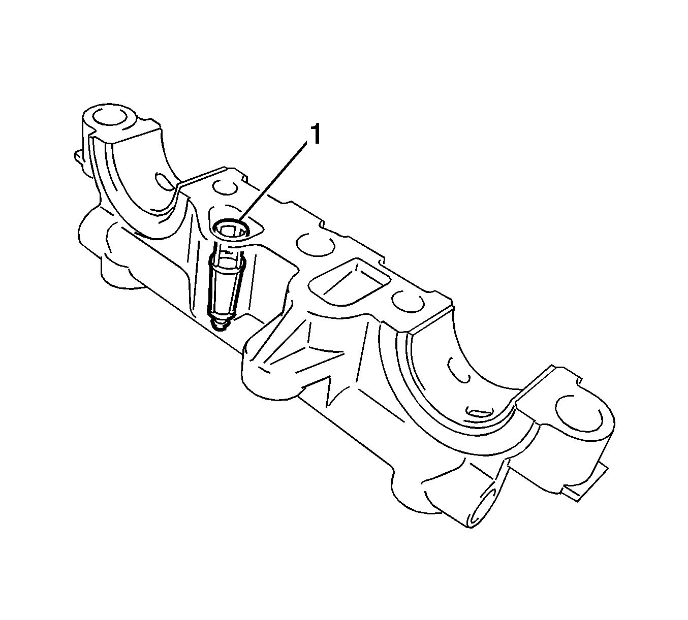
- Install the oil control valve filter (1).
- Clean both surfaces of the bearings.
- Install the 2 camshaft bearings.
- Using vernier calipers, measure the distance between the bearing cap edge and the camshaft bearing edge.
- Clean the camshaft journals.
- Apply a light coat of engine oil to the camshaft journals, camshaft housings and bearing caps.
- Install the exhaust camshaft to the camshaft housing.
- Clean the camshaft journals.
- Apply a light coat of engine oil to the camshaft journals, camshaft housing.
- Install the intake camshaft to the camshaft housing.
- Install the camshaft bearing cap.
- Apply the engine oil to the bearing caps.
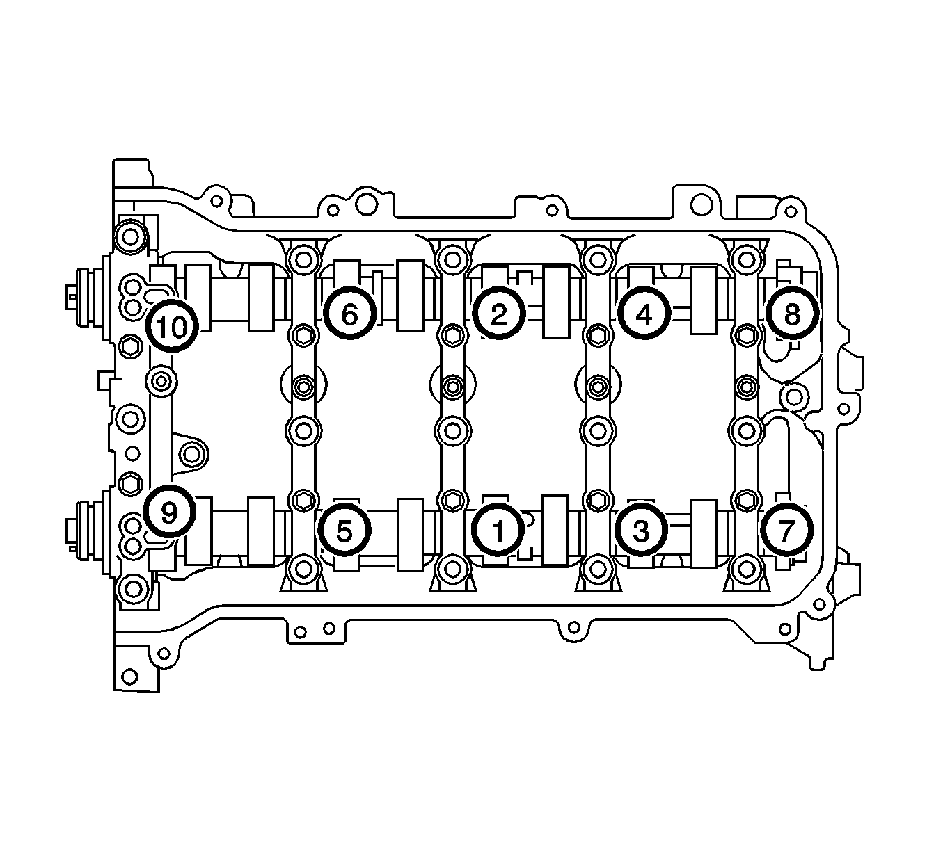
- Make sure of the marks and numbers on the camshaft bearing caps and place them in each proper position and direction.
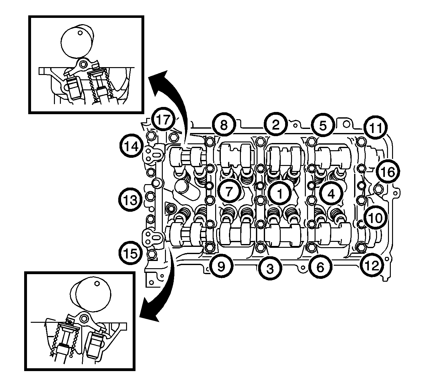
- Install the 10 bolts and tighten in sequence to 16 N·m (12 lb ft).
- Install the camshaft housing sub-assembly.
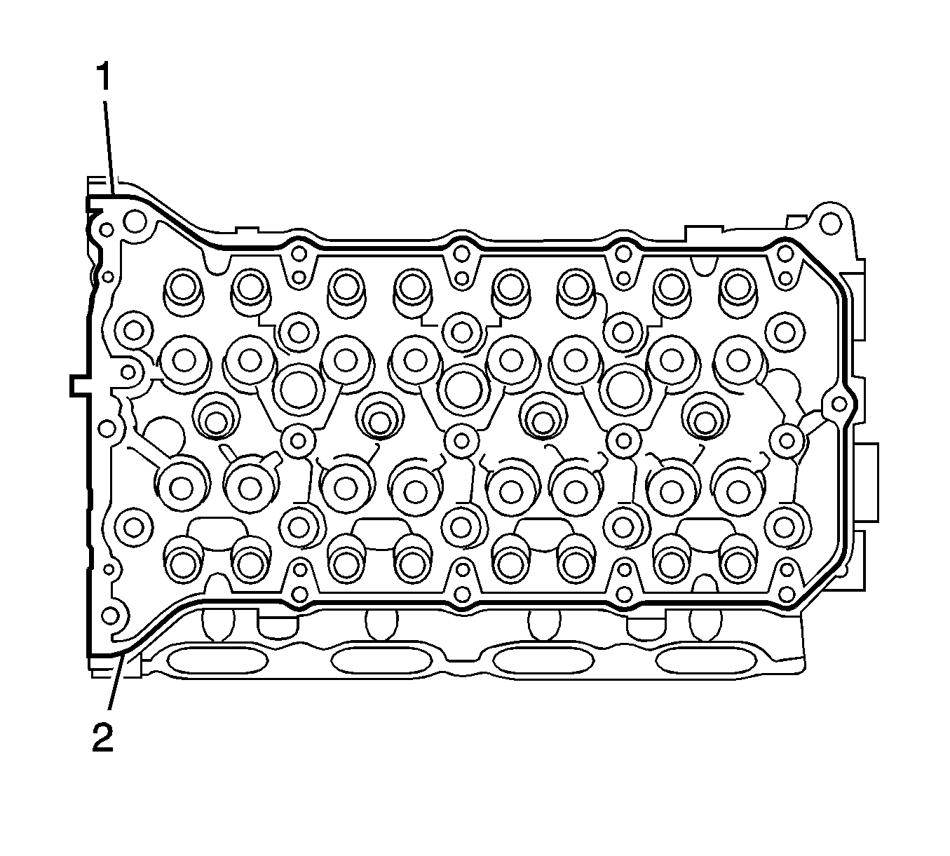
- Apply Three Bond 1207B or equivalent, seal packing in a continuous bead (1).
- Set the intake and exhaust camshafts.
- Install the camshaft housing and 17 bolts and tighten in sequence to 27 N·m (20 lb ft).
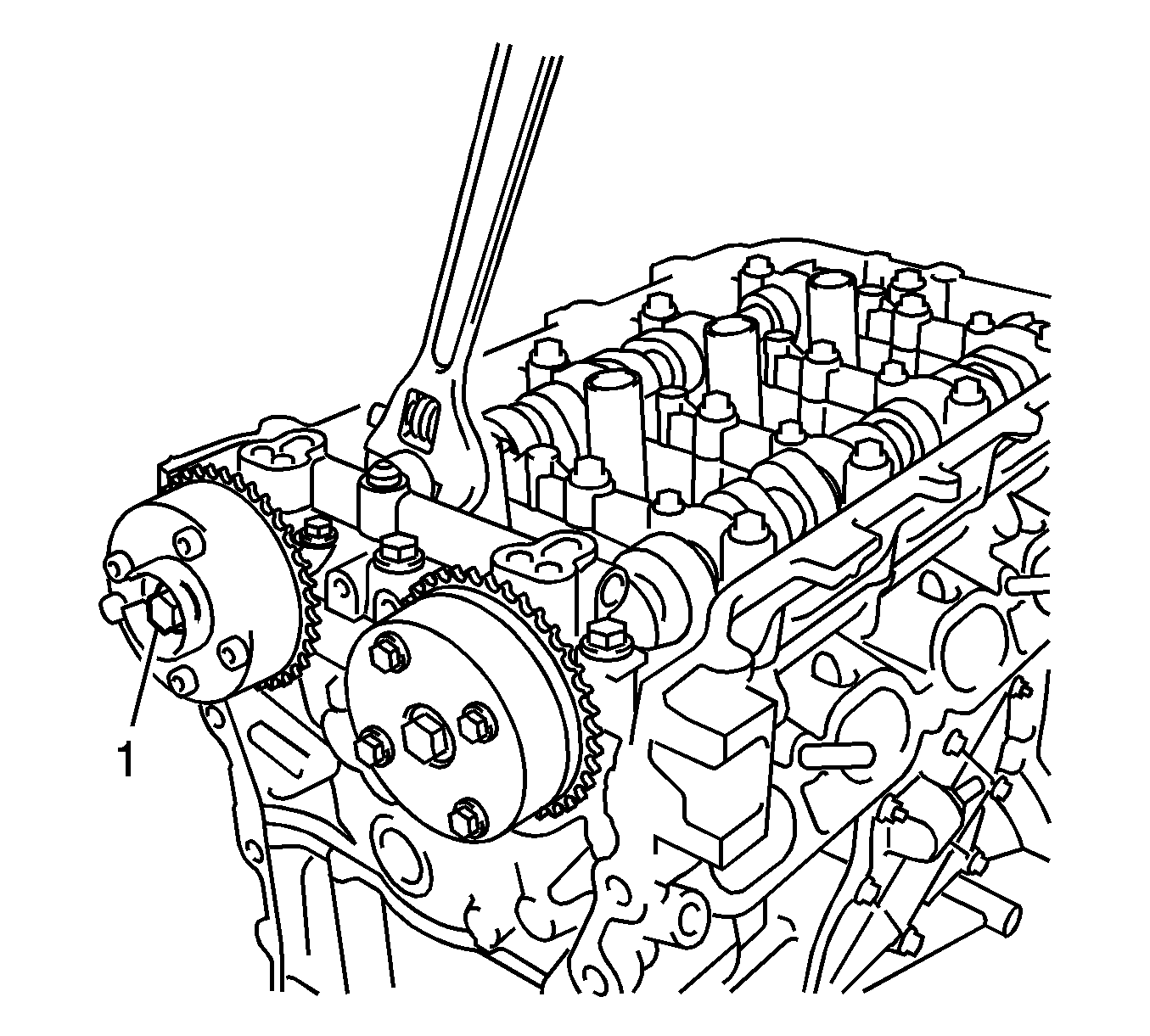
- Install the camshaft timing gear assembly.
- Check that the knock pin is installed on the camshaft.
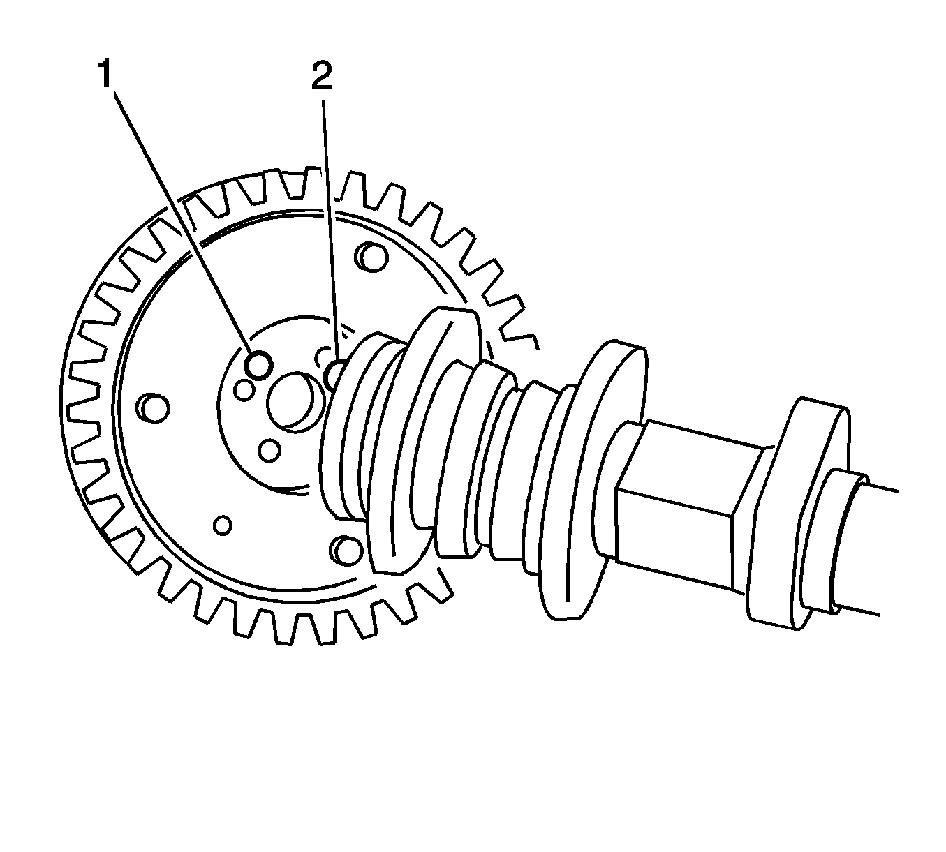
- Put the camshaft timing gear and camshaft together with the straight pin (1) and key groove (2) misaligned.
- Turn the camshaft timing gear, while pushing it gently against the camshaft. Push further at the position where the pin fits into the groove.
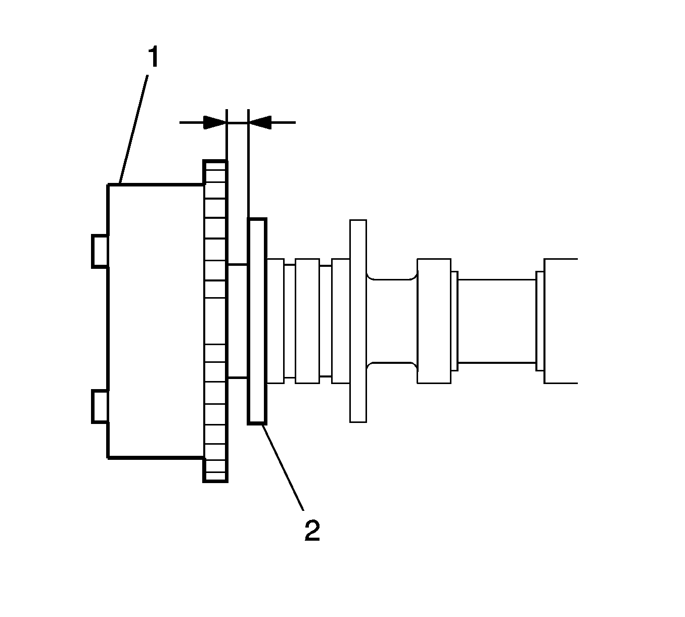
- Measure the clearance between the gear (1) and the camshaft (2).
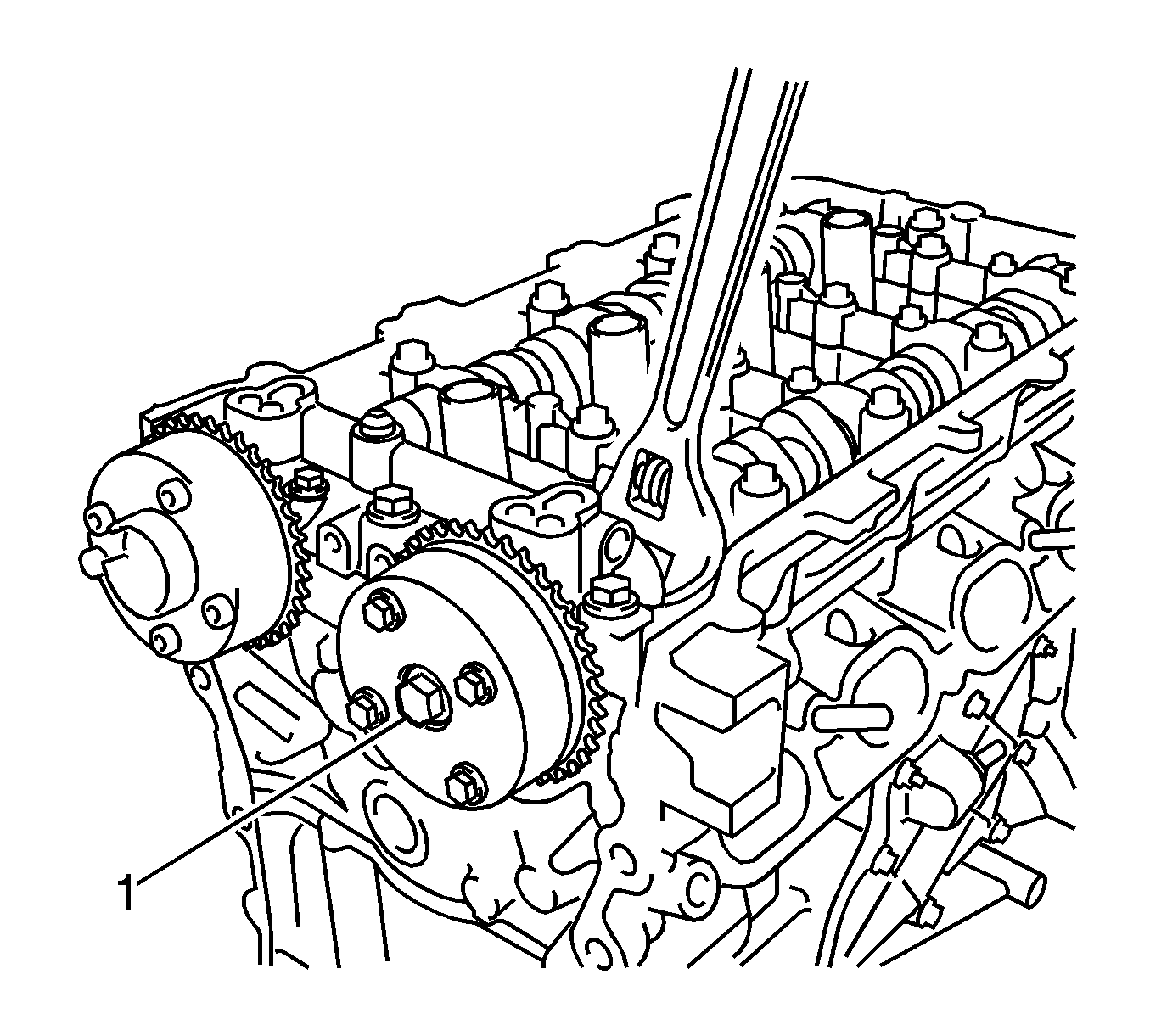
- Install the flange bolt (1) with the camshaft timing gear fixed in place and tighten to 54 N·m (40 lb ft).
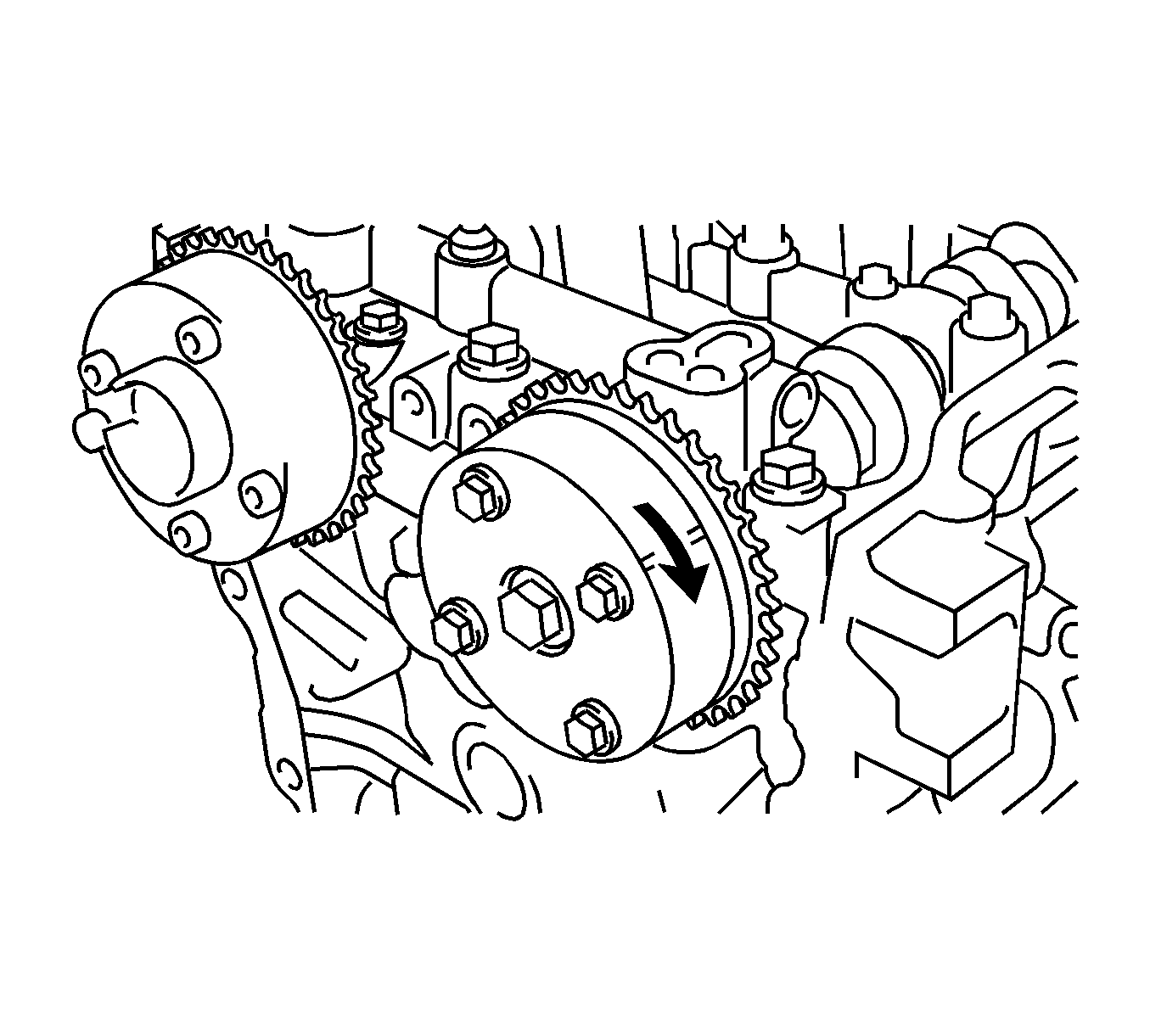
- Check that the camshaft timing gear can move in the retard direction (clockwise) and locks in the most retarded position.
- Install the camshaft timing exhaust gear assembly.
- Check that the knock pin is installed on the camshaft.
- Put the camshaft timing exhaust gear and camshaft together by aligning the key groove (1) and straight pin (2).
- Lightly press the gear against the camshaft, and turn the gear. Push further at the position where the pin enters the groove.
- Check that there is no clearance between the gear flange and the camshaft.
- Install the flange bolt (1) with the camshaft timing exhaust gear fixed and tighten to 54 N·m (40 lb ft).
- Make sure that the camshaft timing exhaust gear is locked.
Note:
• Keep the lash adjuster free of dirt and foreign matter. • Only use clean engine oil.
Note: Install the lash adjuster to the same place it was removed from.
Note: Position the bearings to the center of the bearing cap.
Specification
Dimension: 0.7 mm (0.0276 in) or less
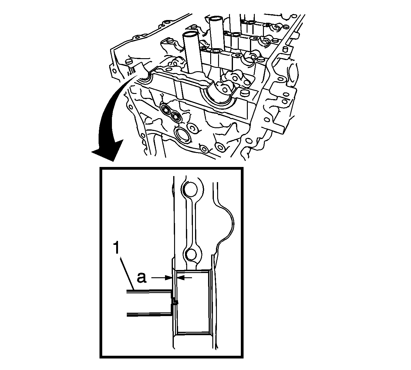
Note: Position the bearings to the center of the bearing cap by measuring dimension A.
Specification
Dimension A: 1.05 to 1.75 mm (0.041 to 0.069 in)
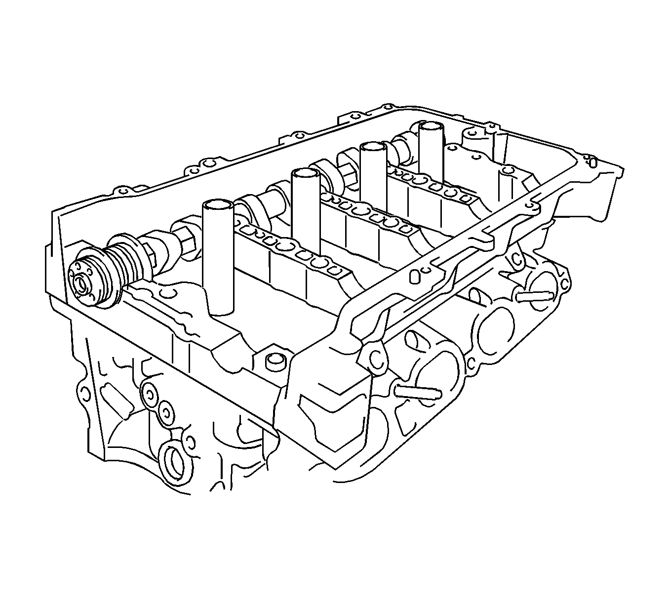
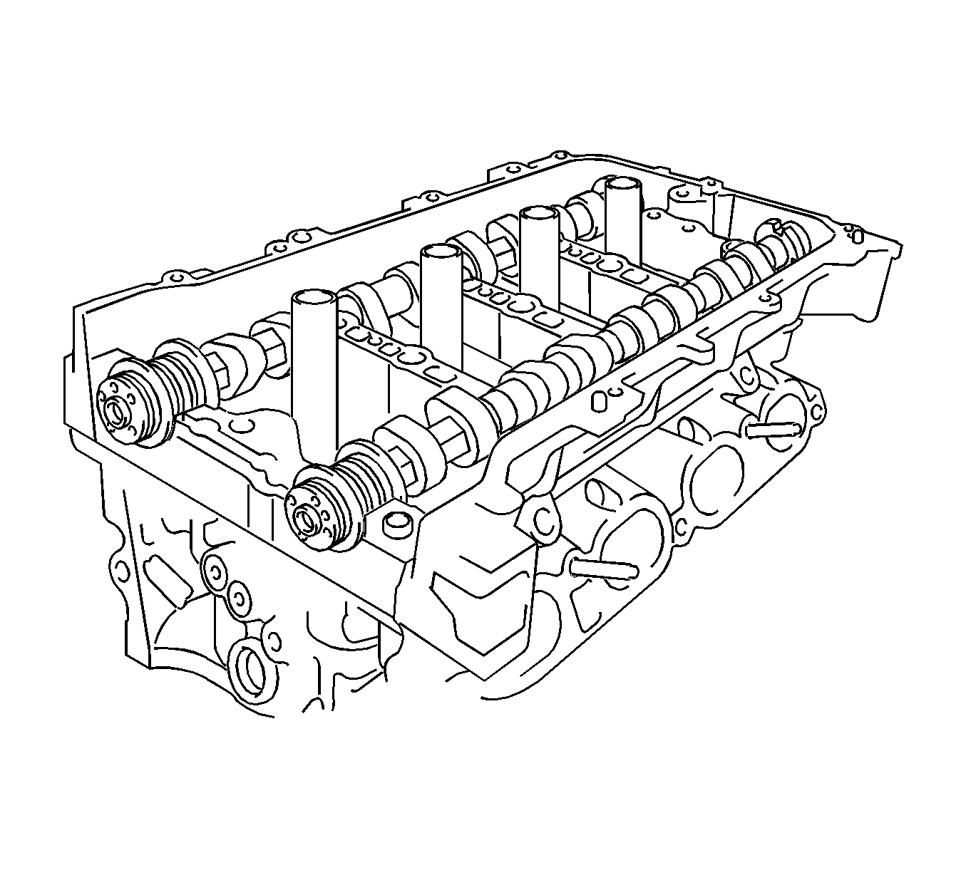
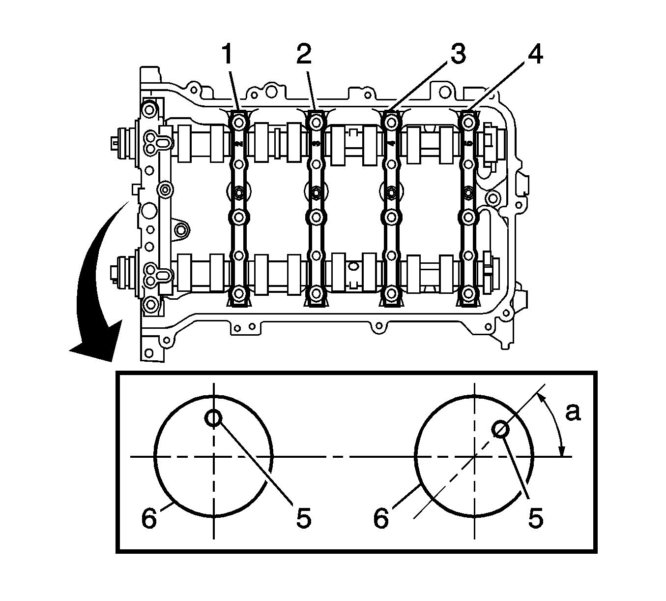
Note: Make sure that the knock pin (5,6) of the camshaft is positioned as shown.
Caution: Refer to Fastener Caution in the Preface section.
Note:
• Remove any oil from the contact surface. • Install the camshaft housing sub-assembly within 3 minutes and tighten the bolts within 15 minutes after applying seal packing. • Do not start the engine for at least 2 hours after installing.
Specification
Bead diameter: 3.5 to 4.0 mm (0.138 to 0.158 in)
Note:
• After installing the camshaft housing, make sure that the cam lobes are positioned as shown. • If any of the bolts are loosened during installation, remove the camshaft housing, clean the installation surfaces, and reapply seal packing. • If the camshaft housing is removed because any of the bolts are loosened during installation, make sure that the previously applied seal packing does not enter any oil passages. • After installing the camshaft housing, wipe off any seal packing that seeped out from between the housing and the cylinder head.
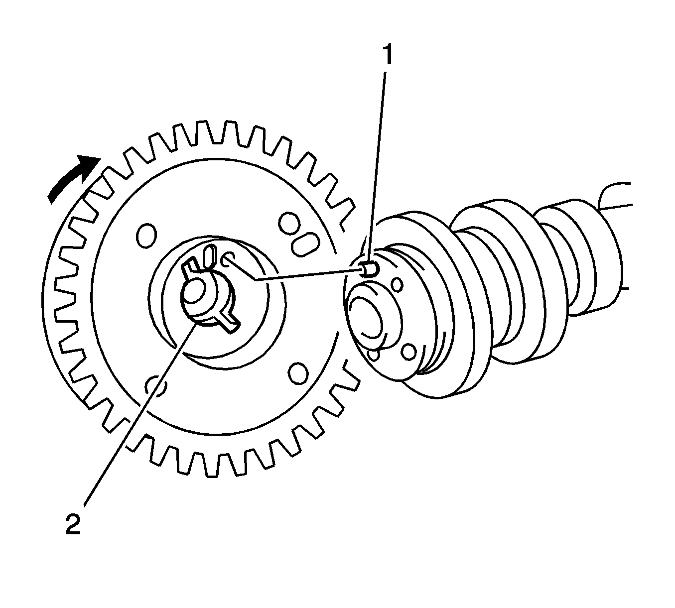
Note: Do not turn the camshaft timing gear in the retard direction (clockwise).
Specification
Clearance: 0.1-0.4 mm (0.004-0.016 in)
Note: Be sure not to turn the camshaft timing exhaust gear in the retard direction (clockwise).
