Special Tools
J-41665-1 Crankshaft Balancer and Sprocket Installer
- Remove the 2 ring pins.
- Install 2 new ring pins to the crankcase.
- Remove the 2 stud bolts from the crankcase.
- Using a TORX socket E5, install the 2 stud bolts (1,2) as shown in the illustration.
- Remove the 2 stud bolts from the water inlet housing.
- Using a TORX socket E5, install the 2 stud bolts and tighten to 5.0 N·m (44 lb in).
- Replace the spark plug tube gasket.
- Pry up the claws of the ventilation baffle plate.
- Remove the 4 gaskets from the cylinder head covers.
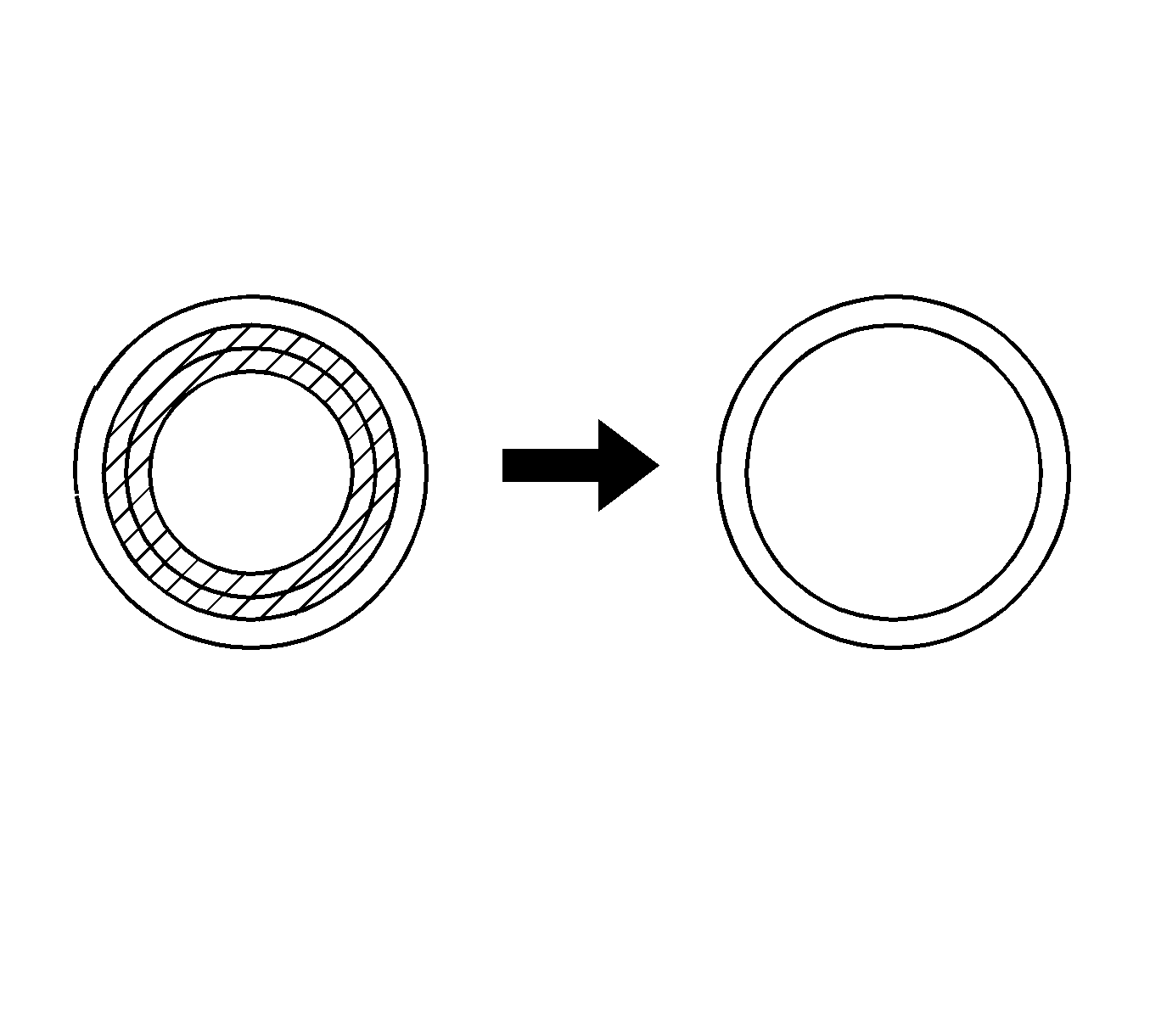
- Using a cutter, cut off the sealing part of the removed plug tube gasket.
- Using a plug tube gasket which has had the sealing part cut off (1), uniformly press in a new plug tube gasket (2) all the way.
- Return the claws (3) of the ventilation baffle plate to their original positions.
- Replace the timing chain cover oil seal.
- Remove the oil seal, using a screwdriver and hammer.
- Using J-41998-A installer (1) and a hammer, tap in the oil seal until its surface is flush with the rear oil seal retainer edge.
- Apply a light coat of MP grease to the lip of the oil seal.
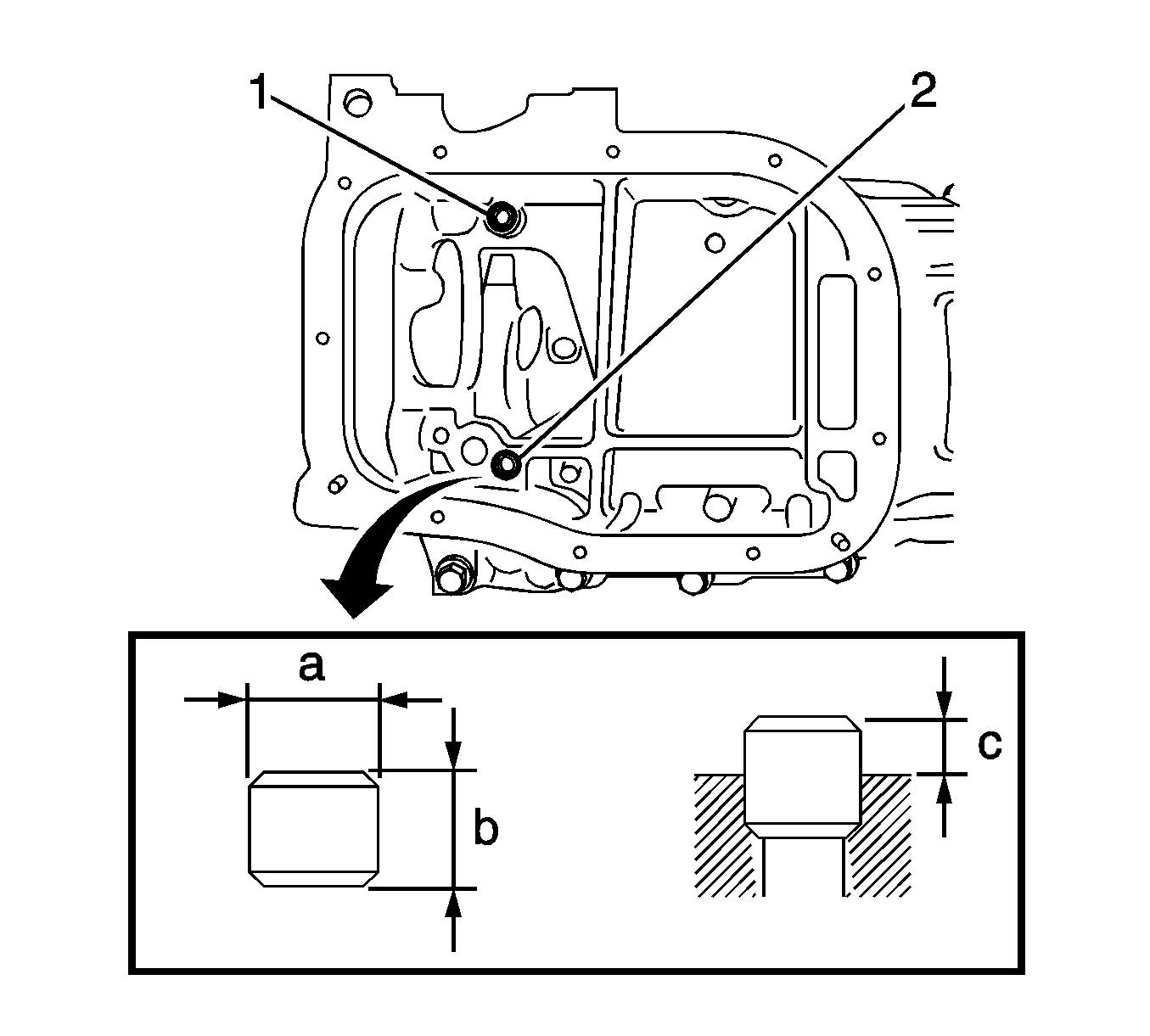
Specification
Standard protrusion (c)-- 3 mm (0.12 in).
Caution: Refer to Fastener Caution in the Preface section.
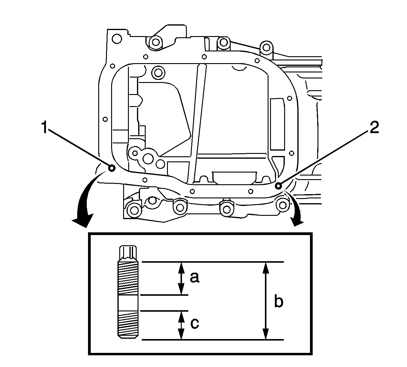
Tighten
Tighten the bolts to 5.0 N·m (44 lb in).
Note: Do not deform the claws of the baffle plate more than necessary.
Note:
• Prevent the plug tube gaskets from being deformed as much as possible. The removed gaskets will be used when reinstalling the gaskets. • Do not damage the connection of the cylinder head cover.
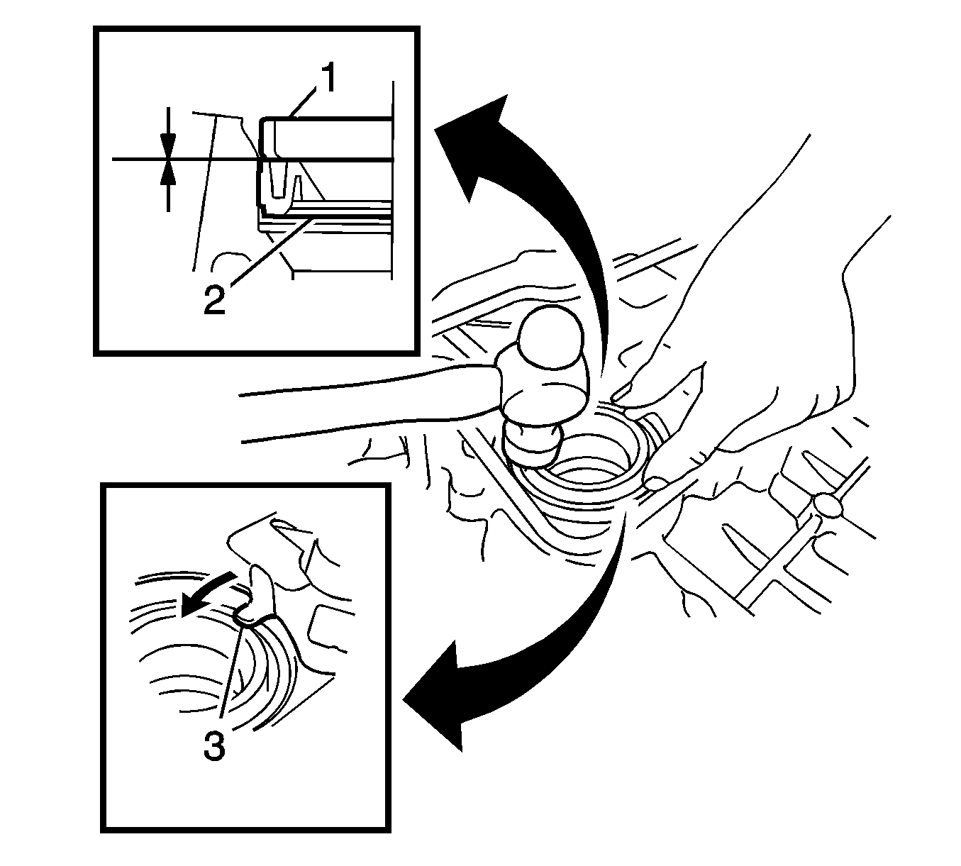
Note: If a plug tube gasket that will be used to install a new gasket is deformed, and cannot be positioned on a new gasket, correct the deformation using pliers.
Note:
• Keep the lip free of foreign matter. • Do not tap on the oil seal at an angle.
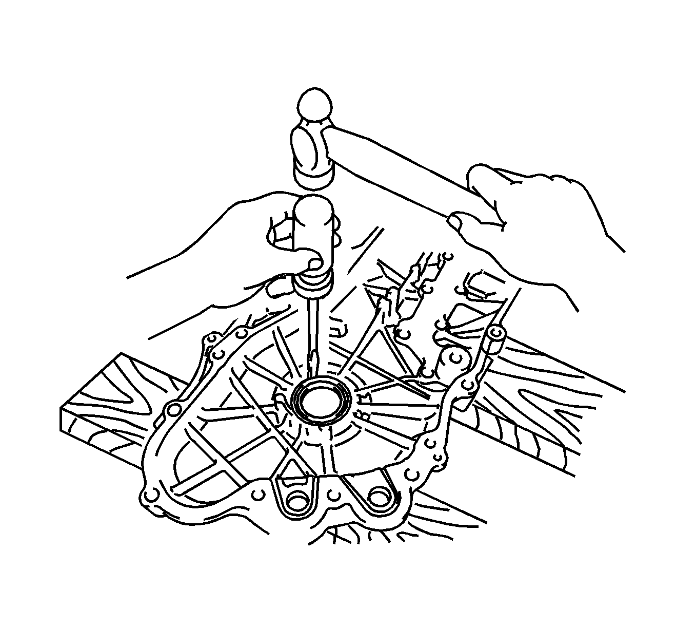
Note: Tape the screwdriver tip before use.
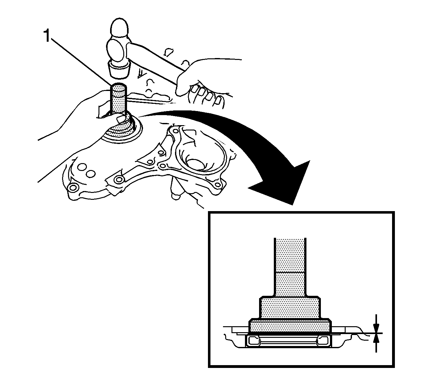
Note:
• Keep the lip free of foreign matter. • Do not tap on the oil seal at an angle. • Make sure that the oil seal edge does not stick out of the timing chain cover.
