Special Tools
EN-49184 Valve Guide Bushing Replacer
Valve Guides
- Replace intake valve guide bush.
- Heat the cylinder head to 80-100°C (176-212°F).
- Place the cylinder head on wooden blocks.
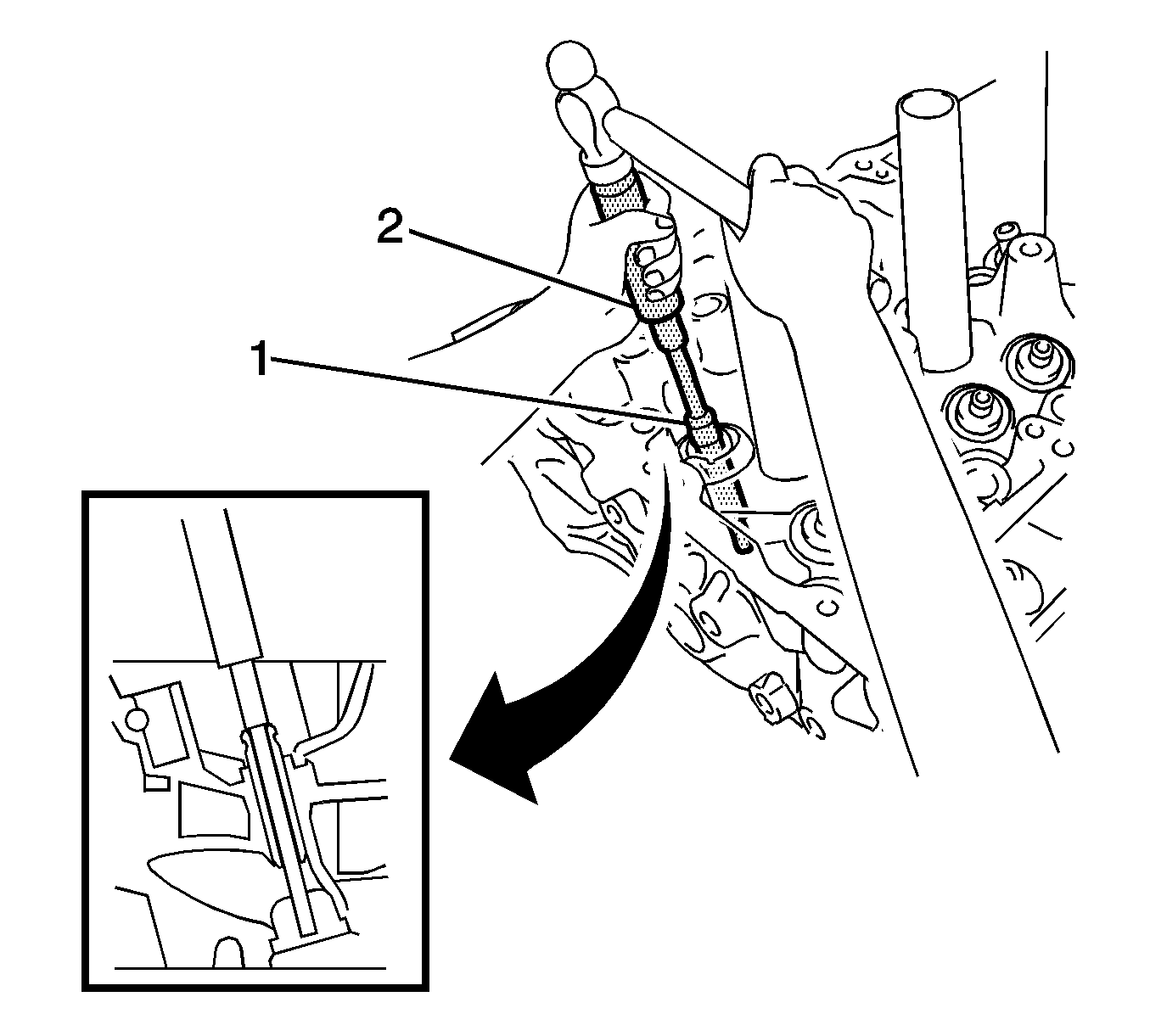
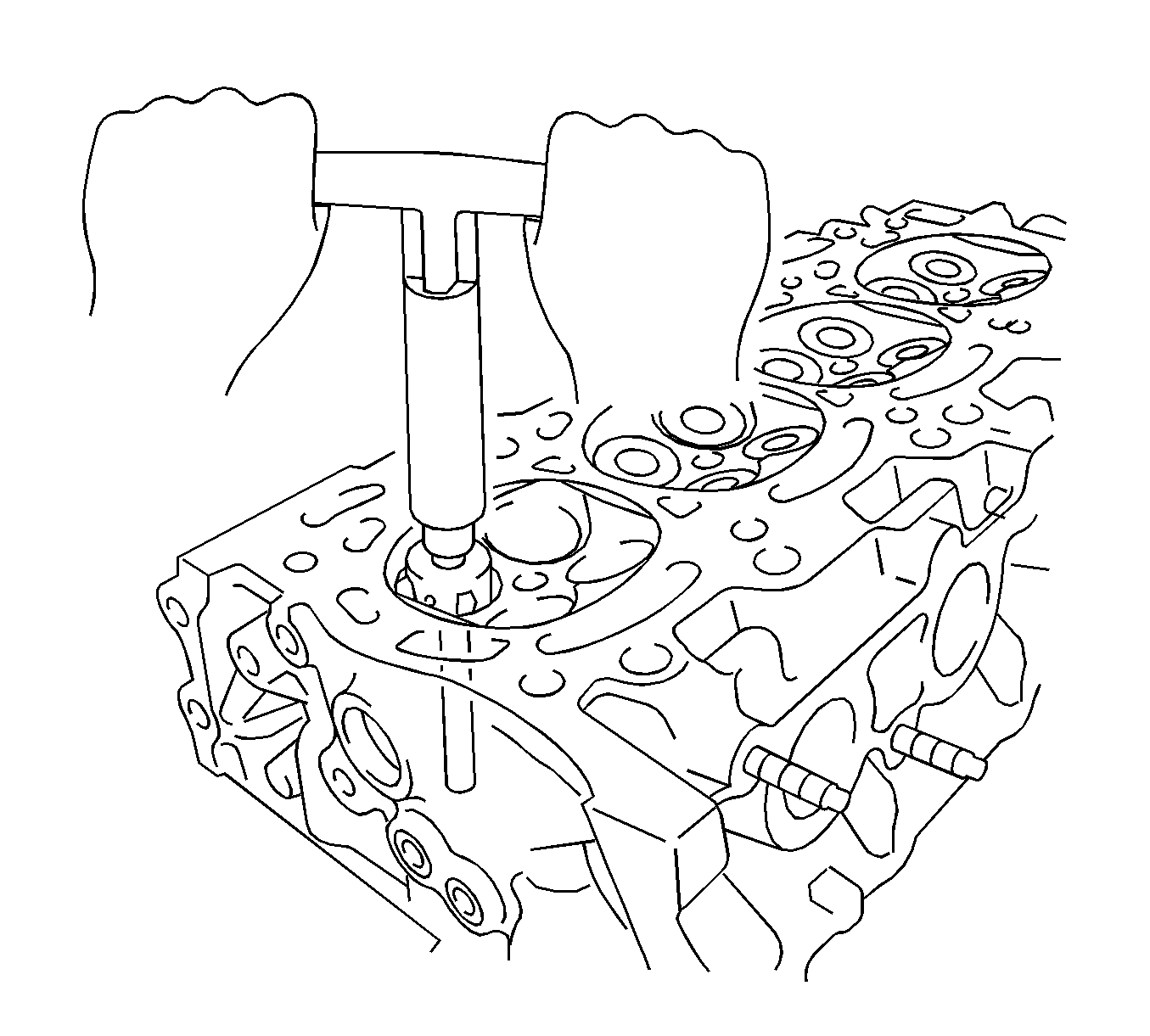
- Using EN-49184 replacer (1) and a hammer, tap out the guide bush.
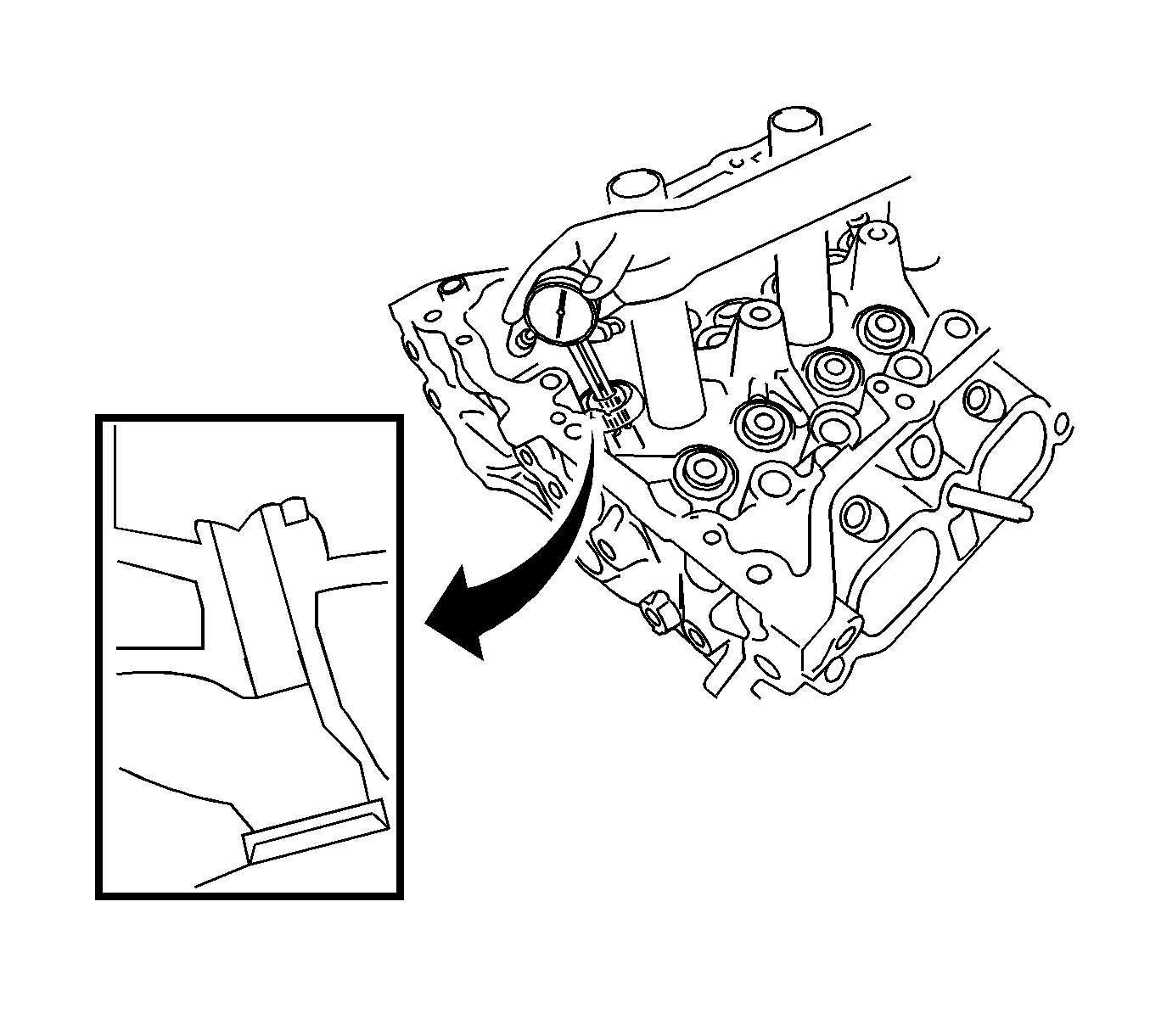
- Using a caliper gauge, measure the bush bore diameter of the cylinder head.
- Select a new guide bush (STD or O/S 0.05).
- If the bush bore diameter of the cylinder head is greater than 10.306 mm (0.4057 in), machine the bush bore to the dimension of 10.335 to 10.356 mm (0.4069 to 0.4077 in) to install an O/S 0.05 valve guide bush. If the bush bore diameter of the cylinder head is greater than 10.356 mm (0.4077 in), replace the cylinder head.
- Heat the cylinder head to 80-100°C (176-212°F).
- Place the cylinder head on wooden blocks.
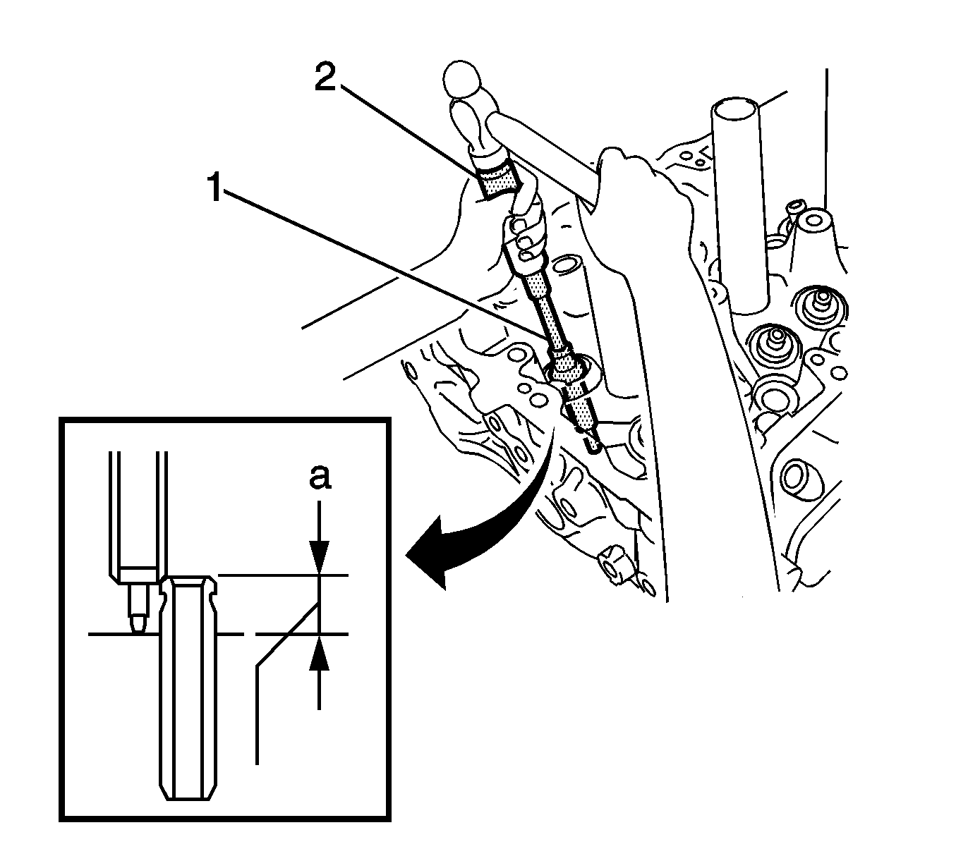
- Using EN-49184 replacer (1) and a hammer, tap in a new guide bush to the specified protrusion height.
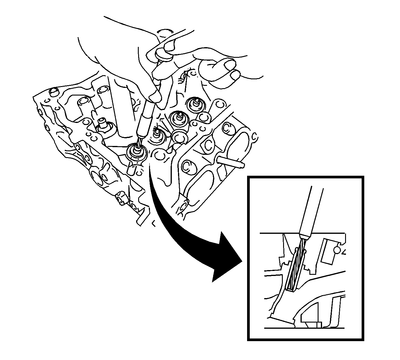
- Using a sharp 5.5 mm reamer, ream the guide bush to obtain the standard clearance between the guide bush and valve stem.
- Replace the exhaust valve guide bush.
- Heat the cylinder head to 80-100°C (176-212°F).
- Place the cylinder head on wooden blocks.
- Using EN-49184 replacer (1) and a hammer, tap out the guide bush.
- Using a caliper gauge, measure the bush bore diameter of the cylinder head.
- If the bush bore diameter of the cylinder head is greater than 10.306 mm (0.4057 in), machine the bush bore to the dimension of 10.335 to 10.356 mm (0.4069 to 0.4077 in) to install an O/S 0.05 valve guide bush. If the bush bore diameter of the cylinder head is greater than 10.356 mm (0.4077 in), replace the cylinder head.
- Heat the cylinder head to 80-100°C (176-212°F).
- Place the cylinder head on wooden blocks.
- Using EN-49184 replacer (1) and a hammer, tap in a new guide bush to the specified protrusion height.
- Using a sharp 5.5 mm reamer, ream the guide bush to obtain the standard clearance between the guide bush and valve stem.
- Remove the ring pins.
- Using a plastic-faced hammer, tap in new ring pins (1) to the specified protrusion height.
- Remove the stud bolts (1).
- Using an E8 TORX socket, install the stud bolts (1).
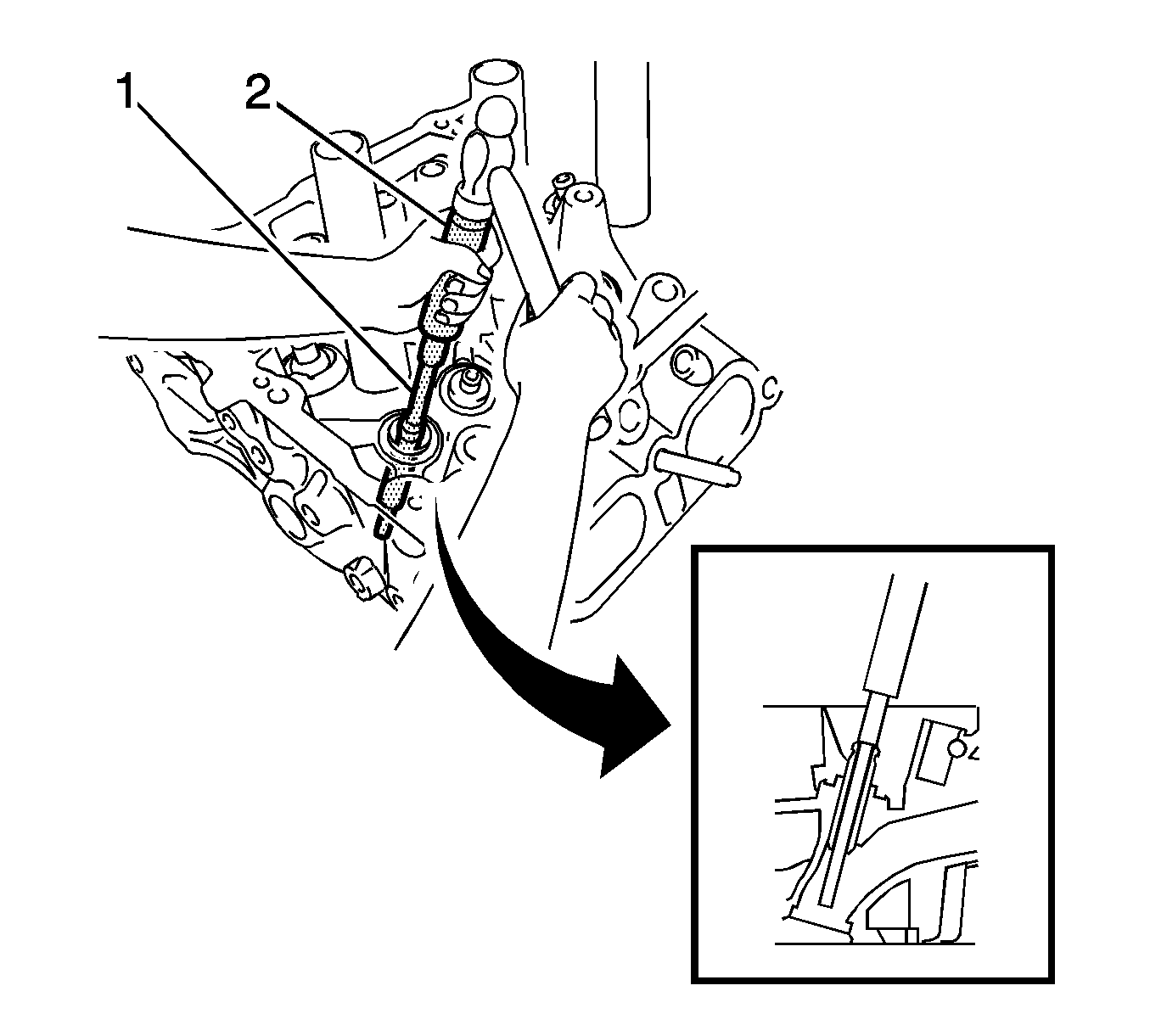
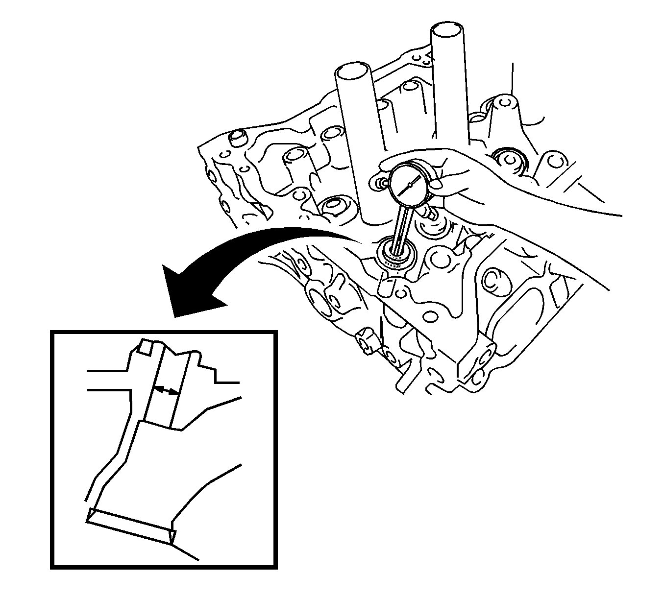
Specification
Cylinder Bore Diameter: 10.285 to 10.306 mm (0.4049 to 0.4057 in)
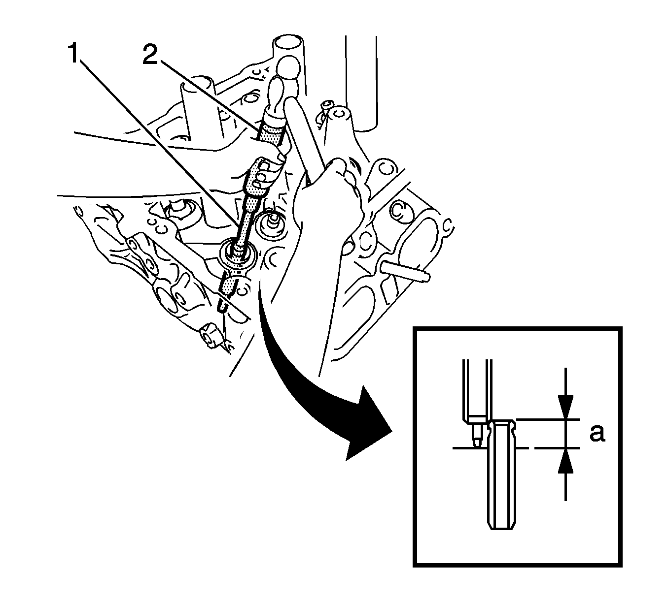
Specification
Protrusion Height: 9.9-10.3 mm (0.3898-0.4055 in)
Specification
Standard Oil Clearance: 0.025-0.060 mm (0.0010-0.0024 in)
Specification
Diameter: 10.285-10.306 mm (0.4049-0.4057 in), select a new guide bush (STD or O/S 0.05)
Specification
Protrusion Height: 11.15-11.55 mm (0.4390-0.4547 in.)
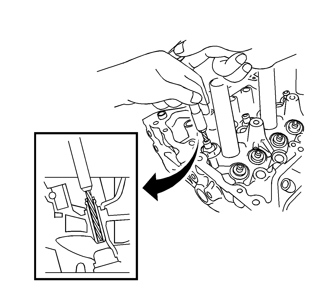
Specification
Standard Oil Clearance: 0.030- 0.065 mm (0.0012-0.0026 in)
Note: It is not necessary to remove the ring pins unless they are being replaced.
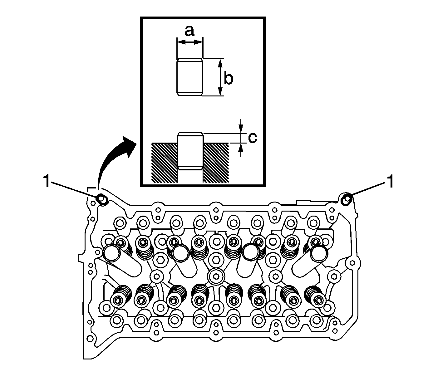
Specification
Protrusion Height: 6.5-7.5 mm (0.26-0.30 in)
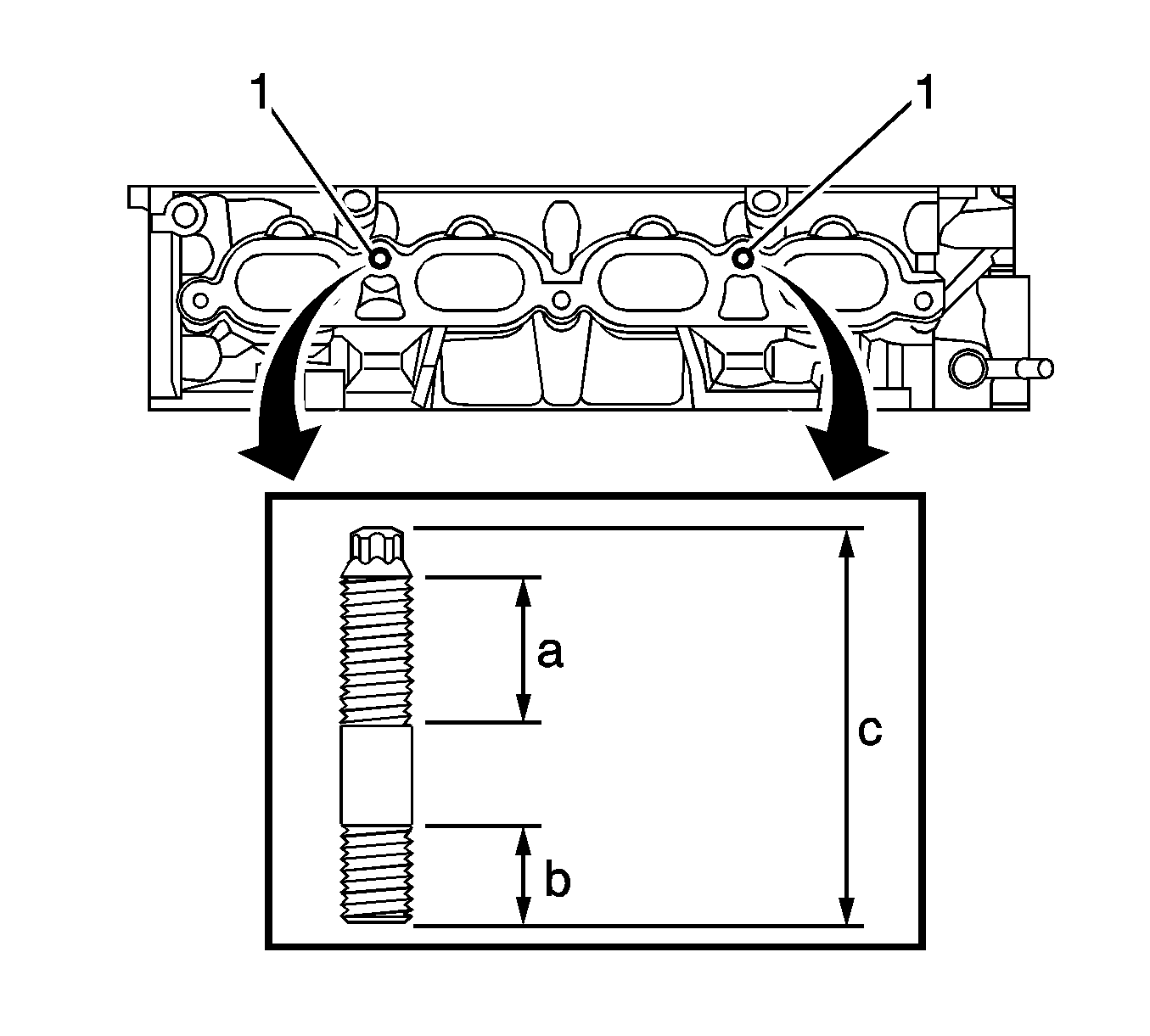
Note: If any of the stud bolts is deformed or the threads are damaged, replace it.
Caution: Refer to Fastener Caution in the Preface section.
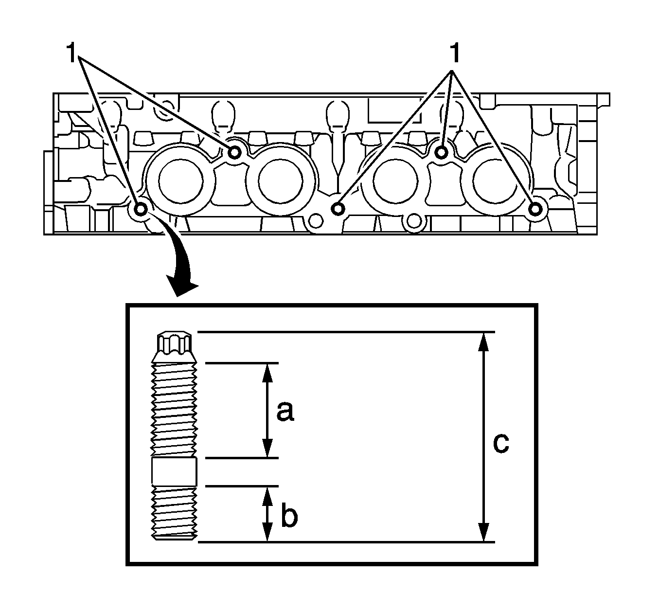
Tighten
Tighten the bolts to 9.5 N·m (84 lb in).
Intake and Exhaust Valves
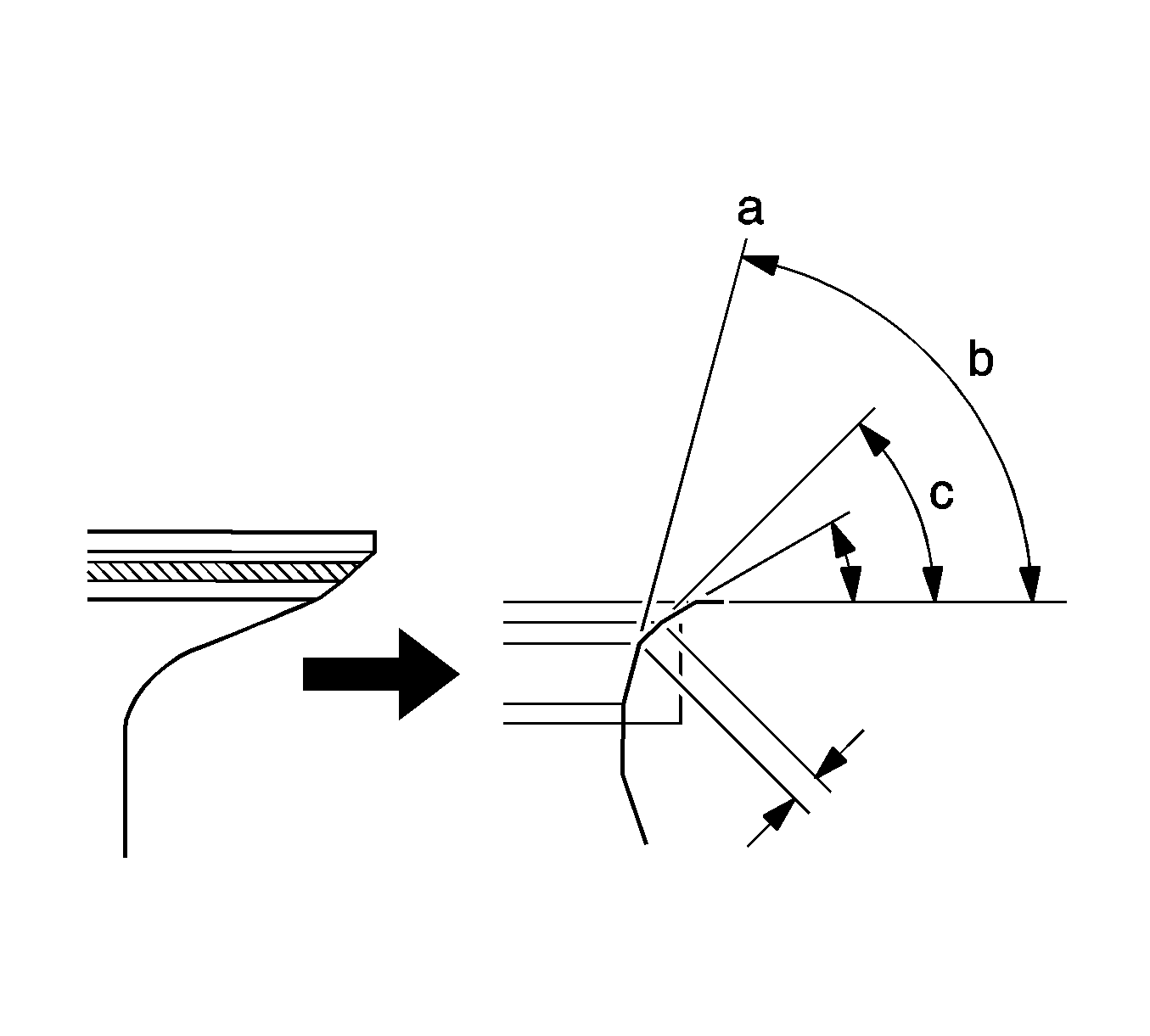
- Using a 45 degree cutter, resurface the valve seat so that the valve seat width is more than the specification.
- Using 30 degree and 75 degree cutters, correct the valve seat so that the valve contacts the entire circumference of the seat. The contact should be in the center of the valve seat, and the valve seat width should be maintained within the specified range around the entire circumference of the seat.
- Handrub the valve and valve seat with an abrasive compound.
- Check the valve seating position.
Note:
• Repair the seat while checking the seating position. • Keep the lip free of foreign matter.
