- Using a screwdriver, install a new snap ring (1) at one end of the piston pin hole.
- Gradually heat the piston to approximately 80-90°C (176-194°F).
- Align the front marks of the piston and connecting rod (1), and push in the piston with your thumb.
- Using a screwdriver, install a new snap ring on the other end of the piston pin hole.
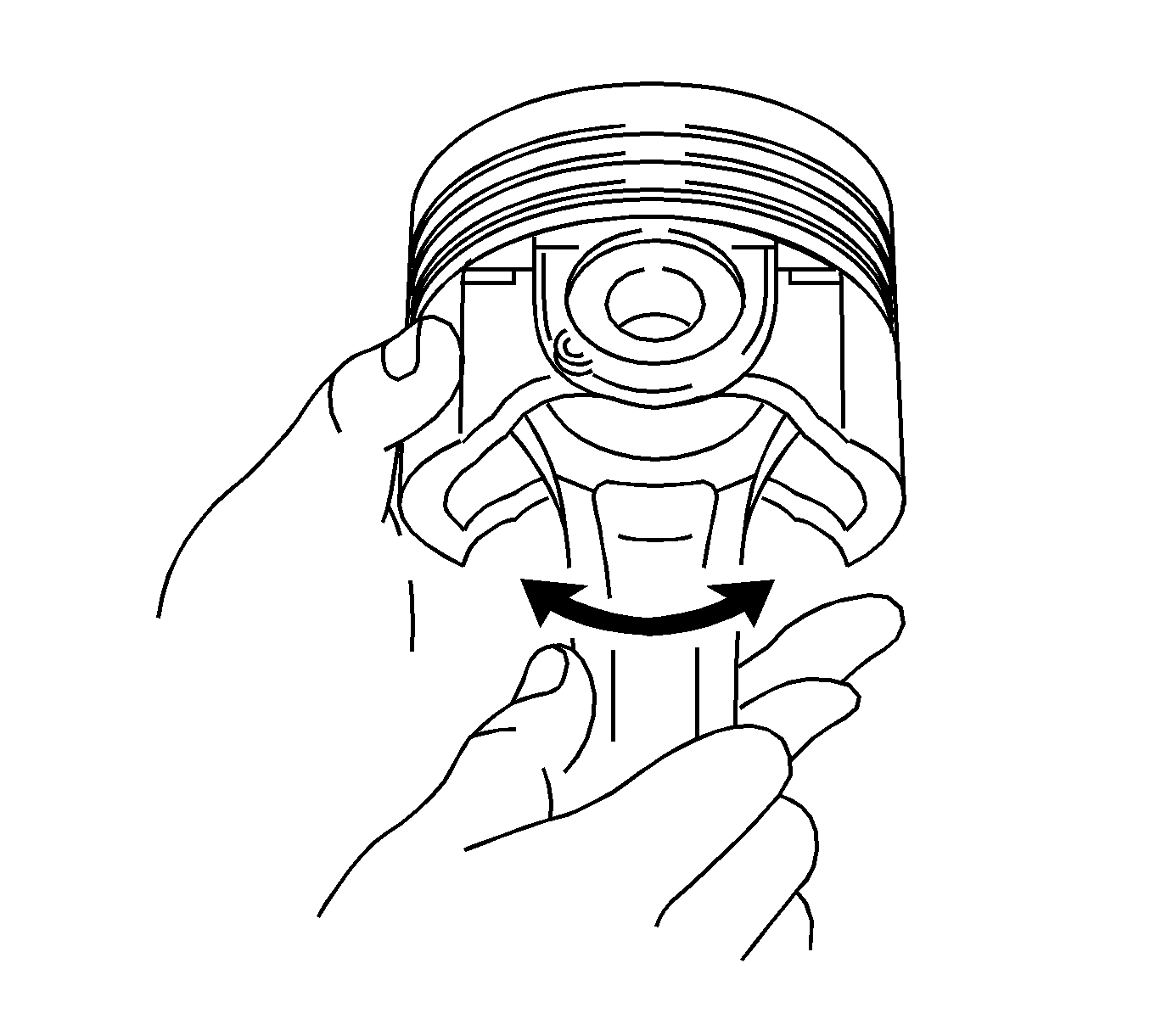
- Check the fitting condition between the piston and piston pin by trying to move the piston back and forth on the piston pin.
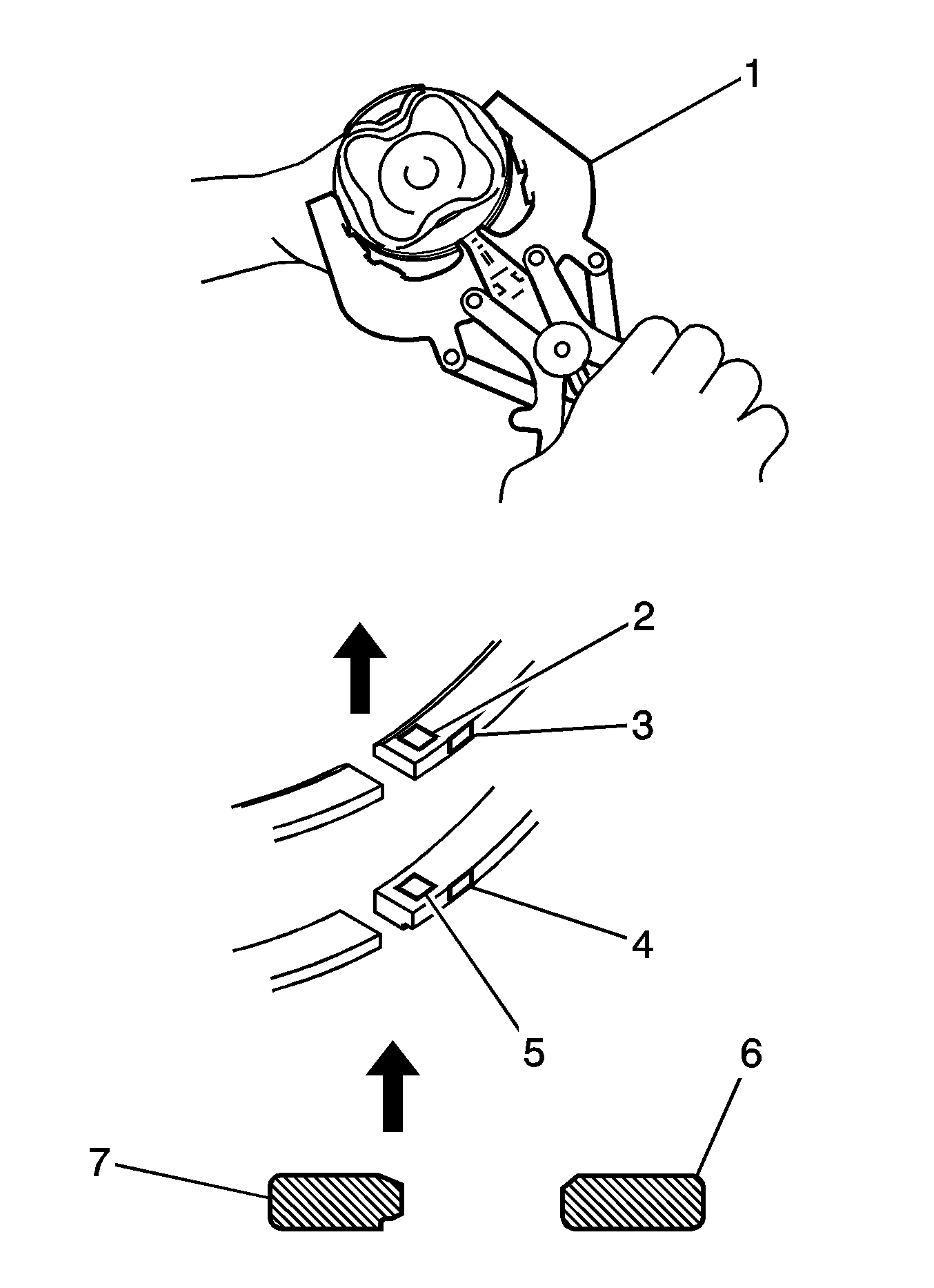
- Install the oil ring expander and oil ring rail by hand.
- Using a piston ring expander (1), install the 2 compression rings so that the paint marks are positioned as shown in the illustration.
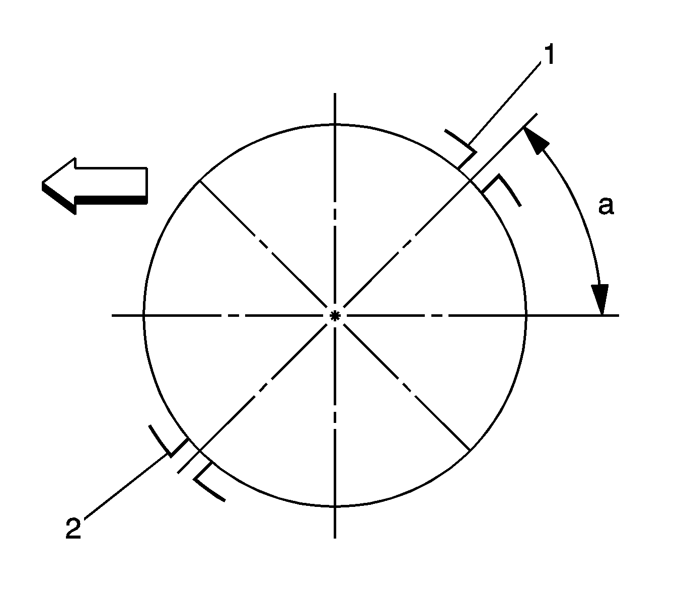
- Position the piston rings so that the ring ends (1,2) are as shown in the illustration.
- Install the upper bearing (for except No. 3 journal).
- Install the upper bearing with an oil groove on the cylinder block.
- Using a scale, measure the distance between the cylinder block edge and the upper bearing edge.
- Install the upper bearing with an oil groove on the cylinder block.
- Using vernier calipers, measure the distance between the cylinder block edge and the upper bearing edge.
- Install the lower bearing onto the bearing cap.
- Using vernier calipers, measure the distance between the bearing cap edge and the lower bearing edge.
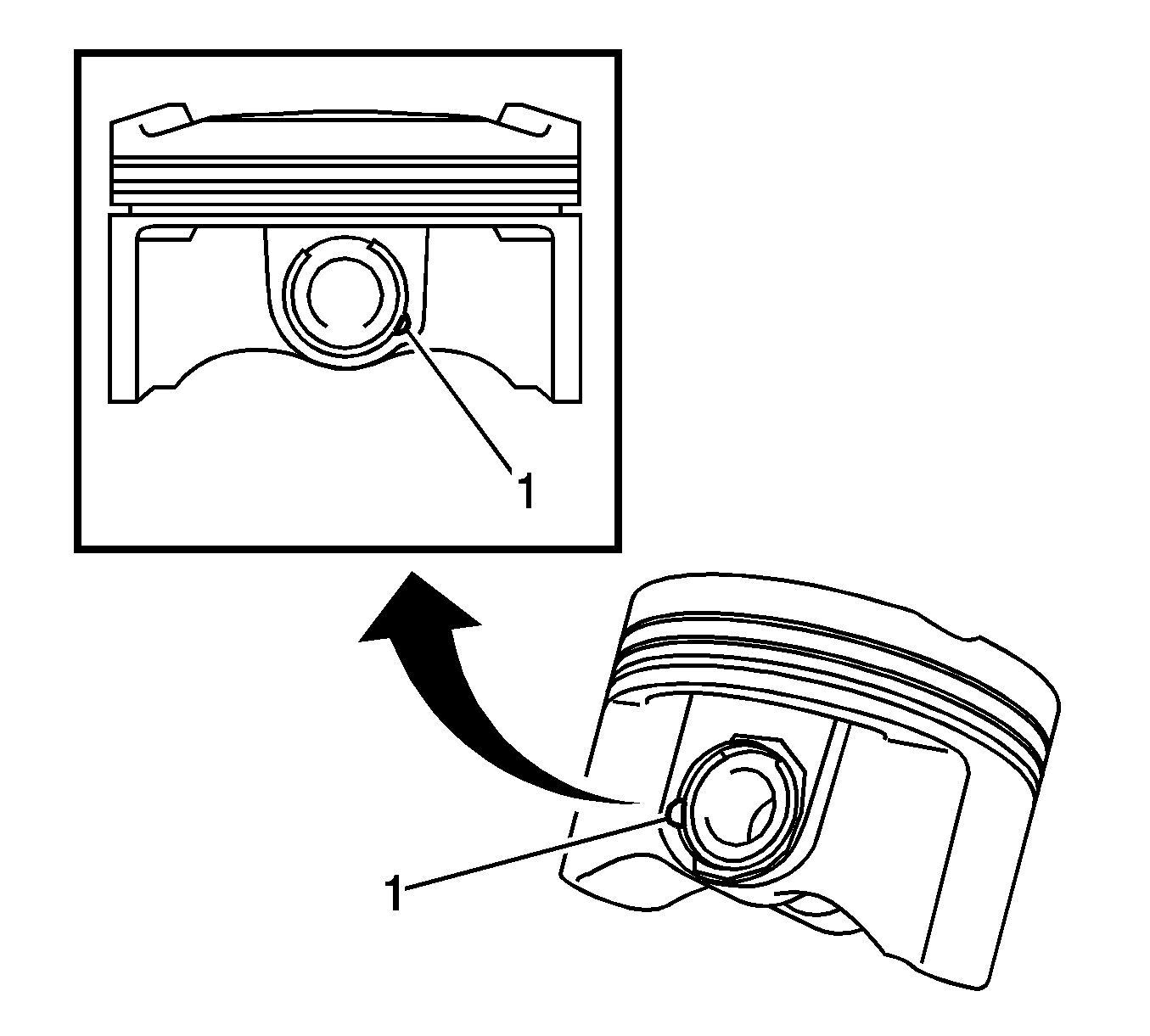
Note: Make sure that the end gap of the snap ring is not aligned with the pin hole cutout portion of the piston.
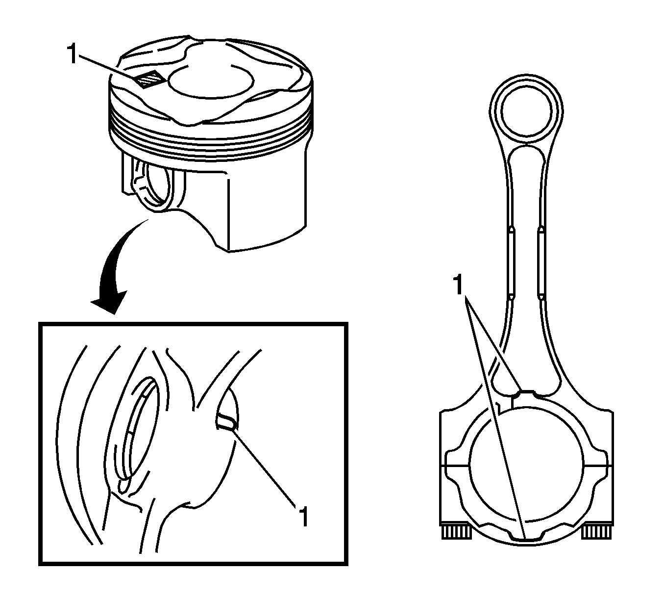
Note: The piston and pin are a matched set.
Note: Make sure that the end gap of the snap ring is not aligned with the pin hole cutout portion of the piston.
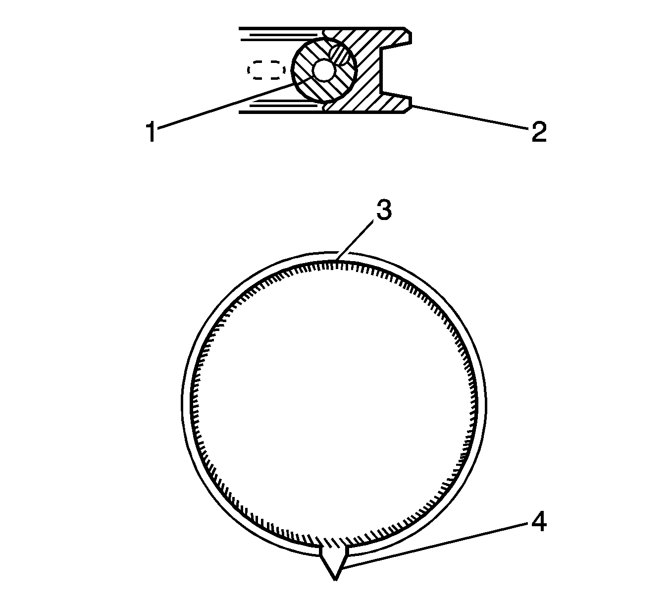
Note:
• Install the expander (1) and oil ring (2) so that their ring ends are at opposite sides (3,4). • Securely install the expander to the inner groove of the oil ring.
Note:
• Install the compression ring No. 1 with the code mark (A1) facing upward (2). • Install the compression ring No. 2 with the code mark (A2) facing upward (5). • Paint marks can only be checked on new piston rings. When reusing piston rings, check each piston ring profile in order to install them into the correct positions.
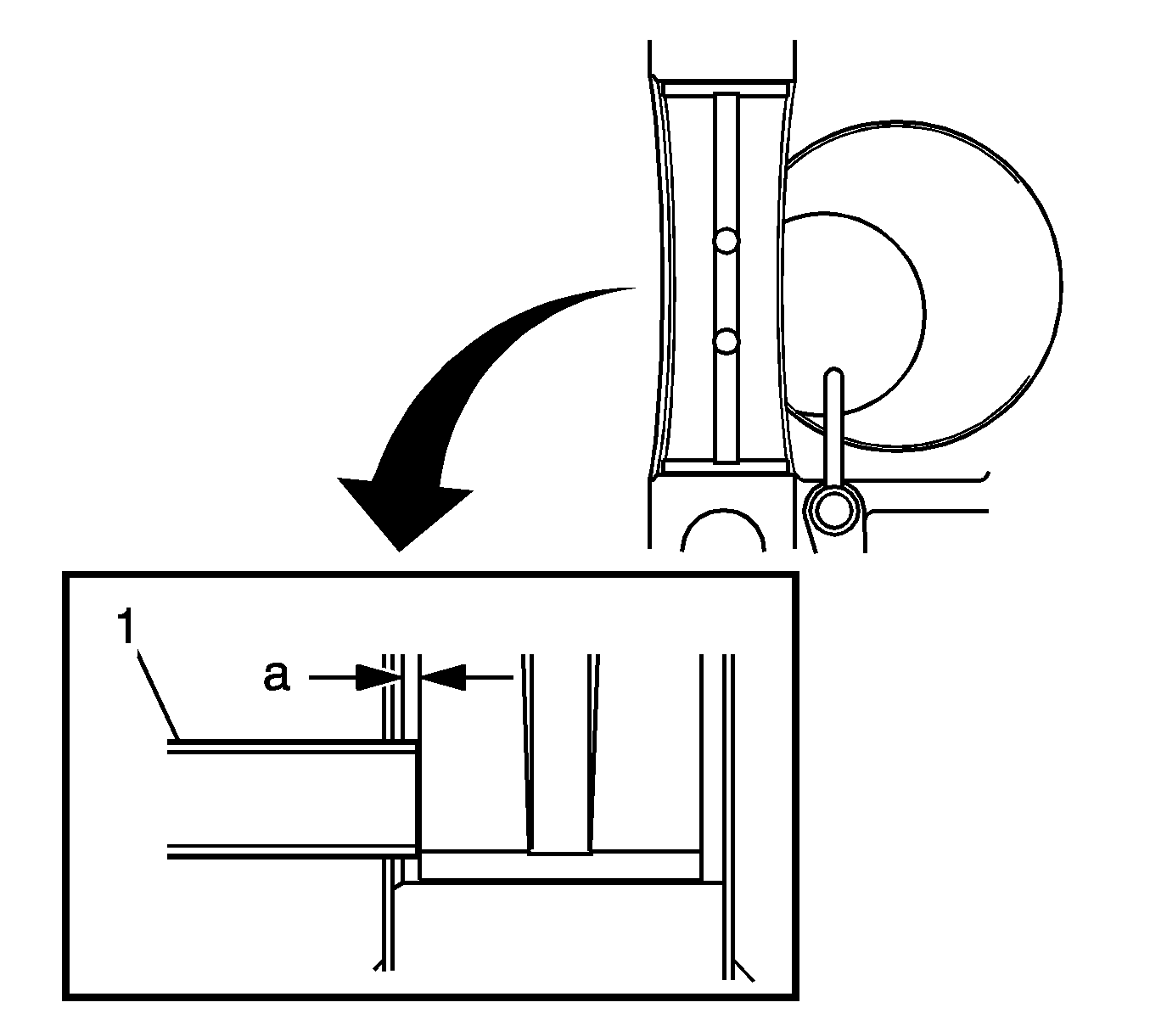
Note: Do not apply engine oil to the bearings or the contact surfaces. Dimension (A): 0.5 to 1.0 mm (0.020 to 0.039 in)
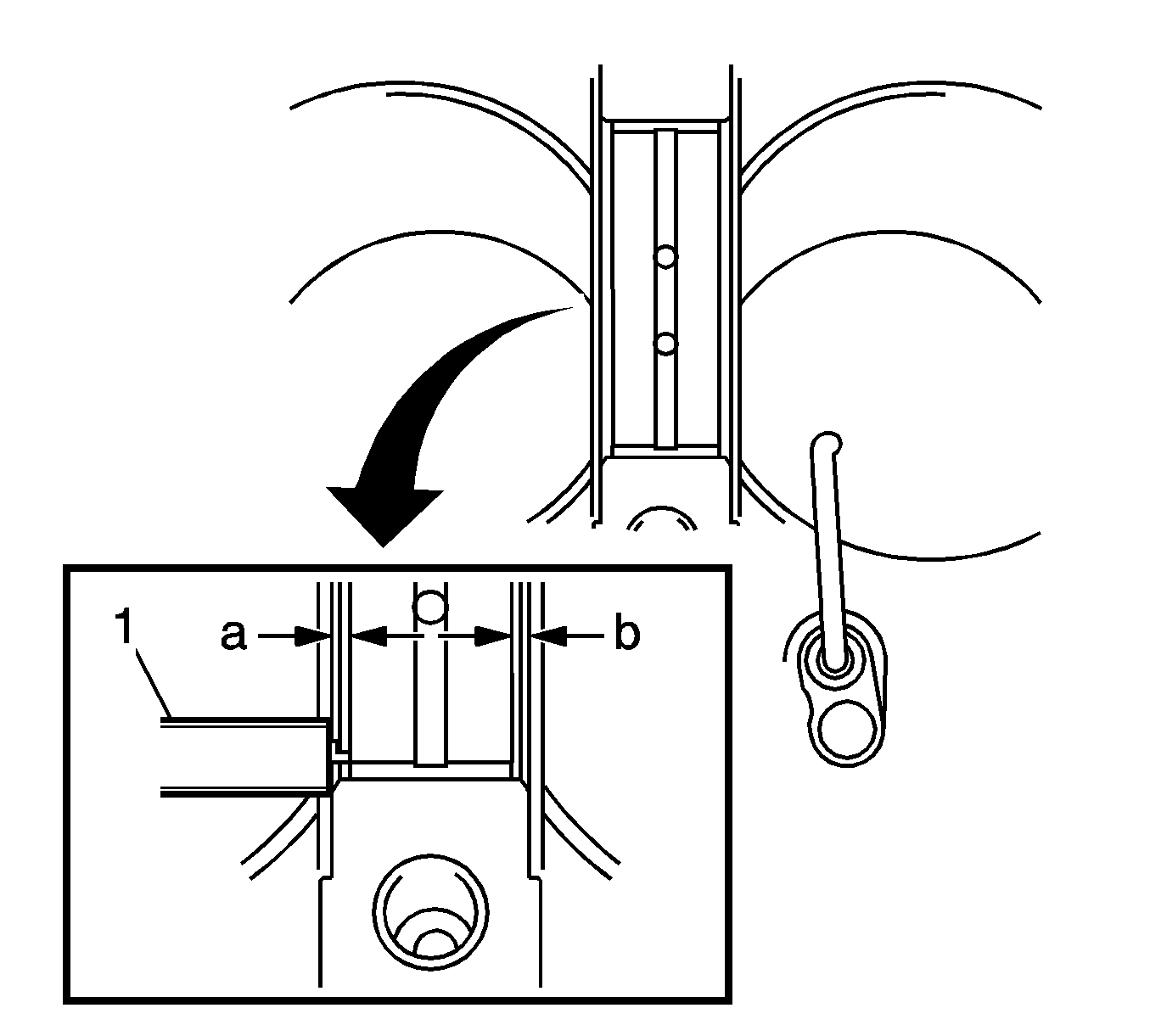
Note: Do not apply engine oil to the bearings or the contact surfaces. Dimension (A - B): 0.5 mm (0.0197 in) or less.
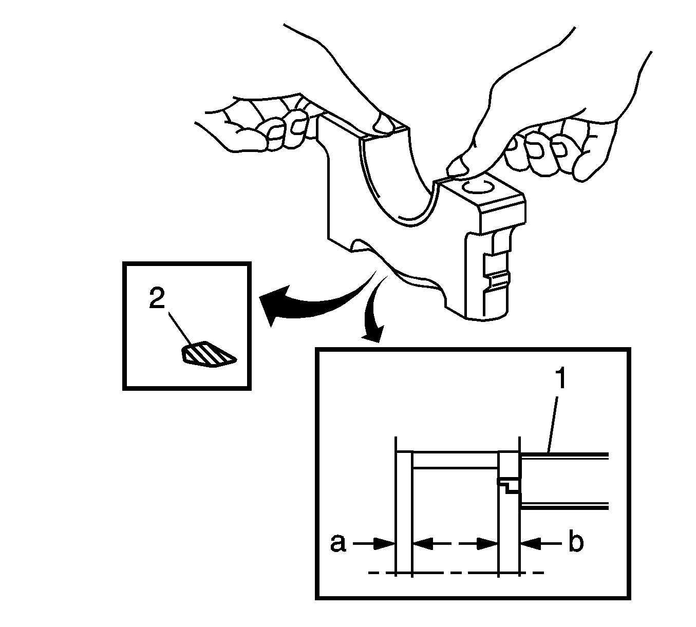
Note: Do not apply engine oil to the bearings or the contact surfaces.
Dimension (A - B): 0.5 mm (0.0197 in) or less
