- Inspect connecting rod thrust clearance.
- Install the connecting rod cap.
- Using a dial indicator, measure the thrust clearance while moving the connecting rod back and forth.
- If the thrust clearance is greater than the maximum, replace the connecting rod assemblies as necessary. If necessary, replace the crankshaft.
- Inspect connecting rod oil clearance.
- Clean the crank pin and bearing.
- Check the crank pin and bearing for pitting and scratches.
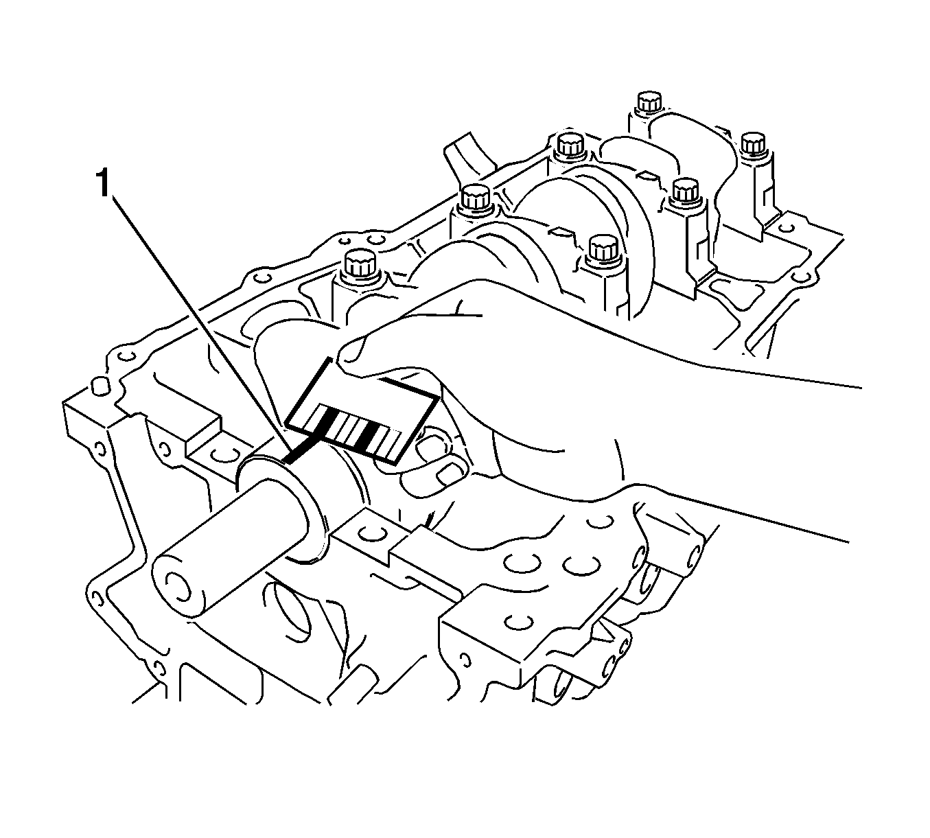
- Lay a strip of Plastigage (1) on the crank pin.
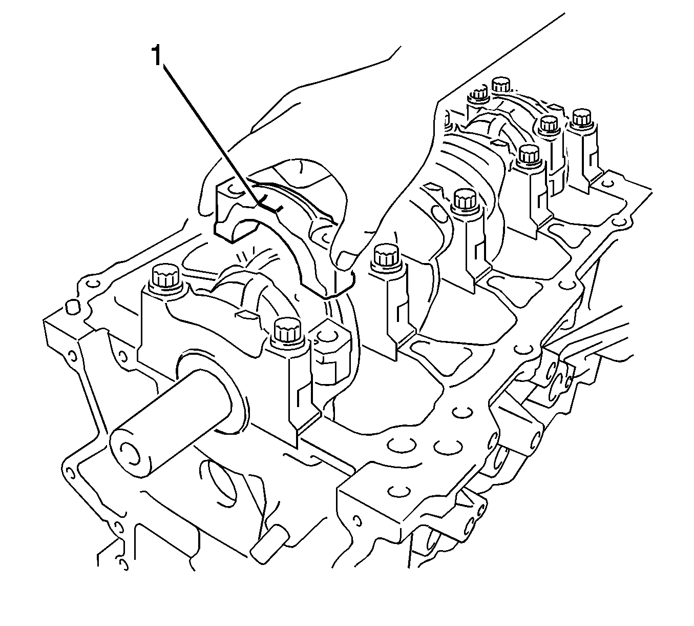
- Check that the front mark (1) of the connecting rod cap is facing forward.
- Install the connecting rod cap.
- Remove the 2 bolts and connecting rod cap.
- Measure the Plastigage at its widest point.
- If the oil clearance is greater than the maximum, replace the connecting rod bearings. If necessary, inspect the crankshaft.
- Inspect the crankshaft.
- Using a dial indicator and V-blocks, measure the circle runout as shown in the illustration.
- If the taper and distortion are greater than the maximum, replace the crankshaft.
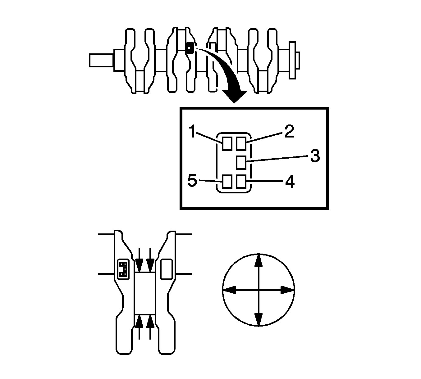
- Using a micrometer, measure the diameter of each main journal.
- If the diameter is not as specified, check the crankshaft oil clearance.
- Check each main journal for taper and distortion as shown in the illustration.
- If the taper and distortion are greater than the maximum, replace the crankshaft.
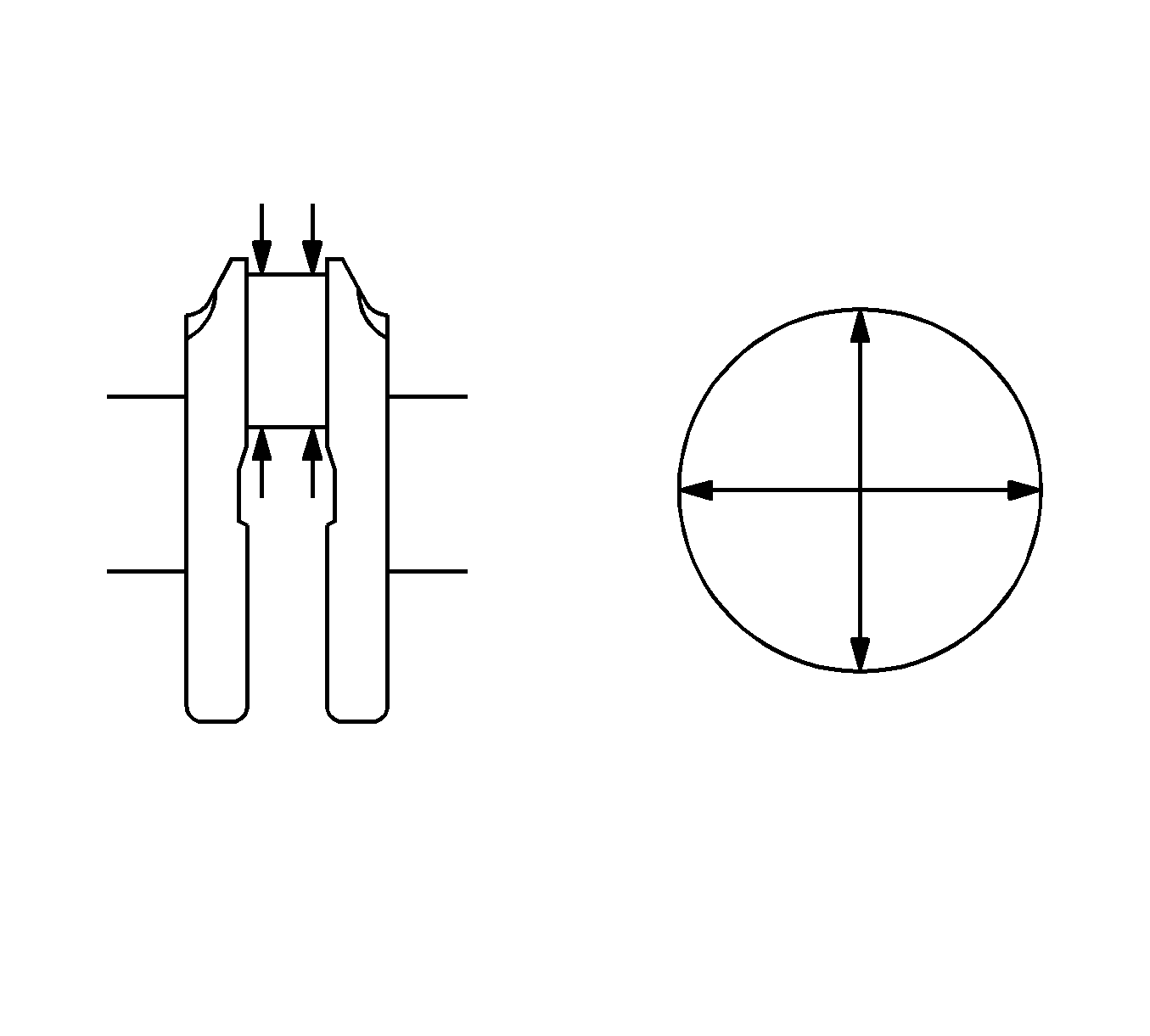
- Using a micrometer, measure the diameter of each crank pin.
- If the diameter is not as specified, check the connecting rod oil clearance.
- Inspect each crank pin for taper and distortion as shown in the illustration.
- If the taper and distortion are greater than the maximum, replace the crankshaft.
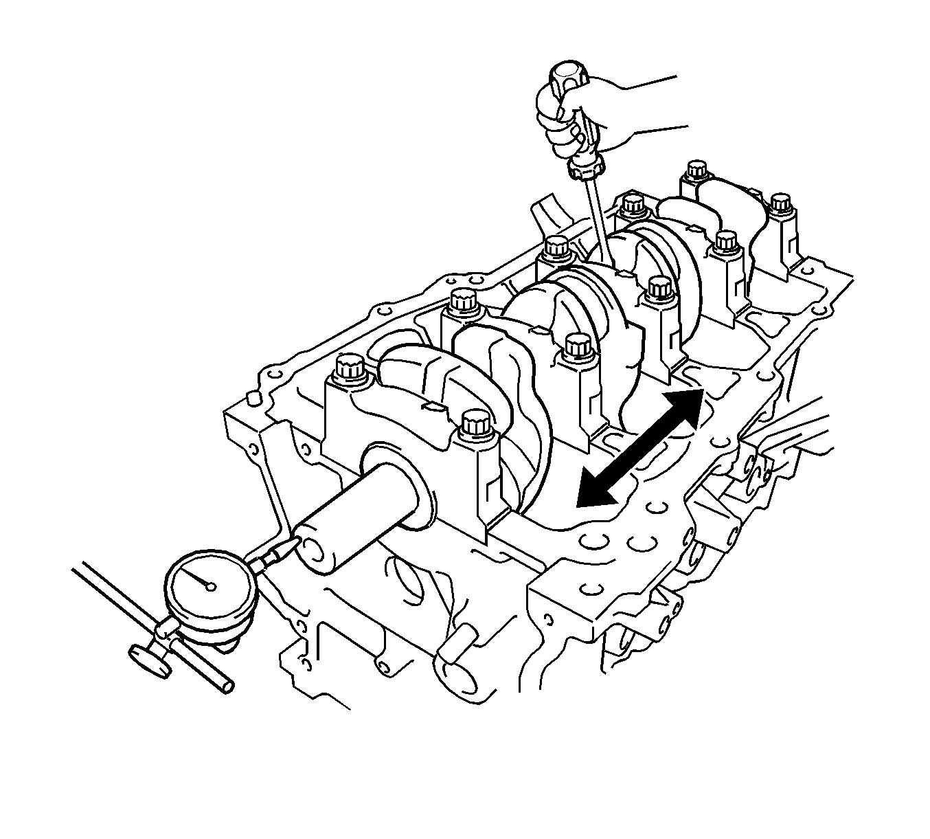
- Inspect crankshaft thrust clearance.
- Install the main bearing cap.
- Using a dial indicator, measure the thrust clearance while prying the crankshaft back and forth with a screwdriver.
- If the thrust clearance is greater than the maximum, replace the thrust washers as a set.
- Inspect the crankshaft oil clearance.
- Check the crank journal and bearing for pitting and scratches.
- Install the crankshaft bearing.
- Place the crankshaft on the cylinder block.
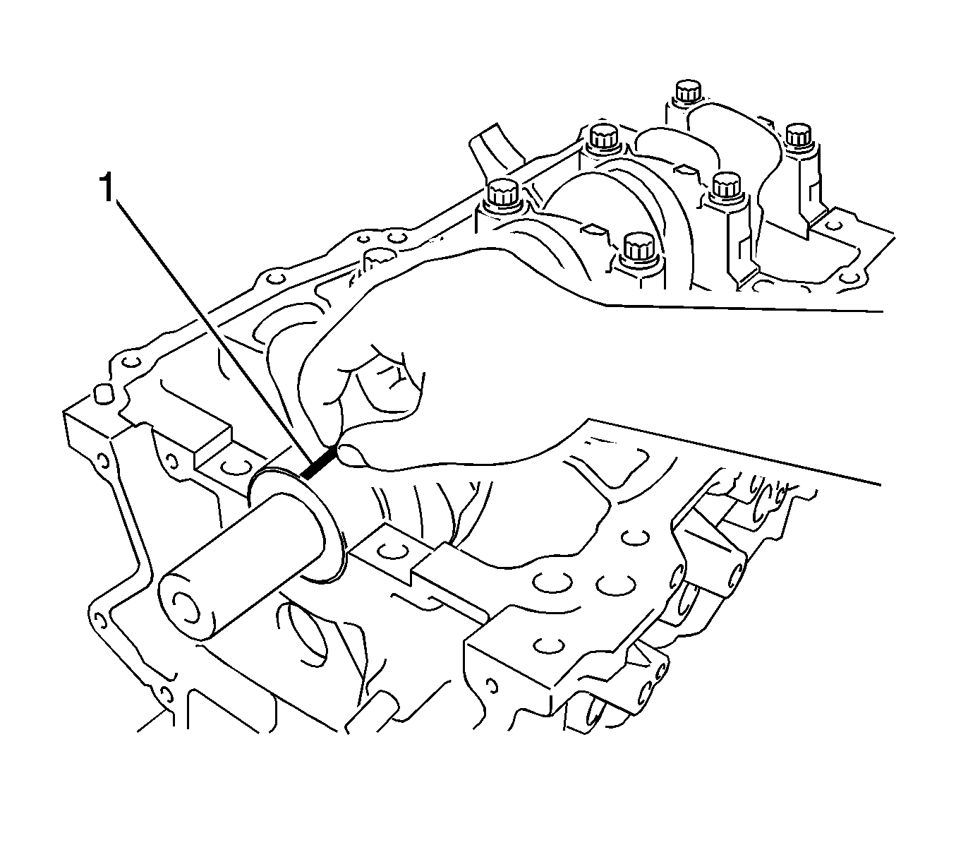
- Lay a strip of Plastigage (1) across each journal.
- Examine the front marks and numbers and install the bearing caps on the cylinder block
- Install the main bearing cap.
- Remove the main bearing caps.
- Measure the Plastigage (1) at its widest point.
- If the oil clearance is greater than the maximum, replace the crankshaft bearing. If necessary, replace the crankshaft.
- Inspect the cylinder head set bolt.
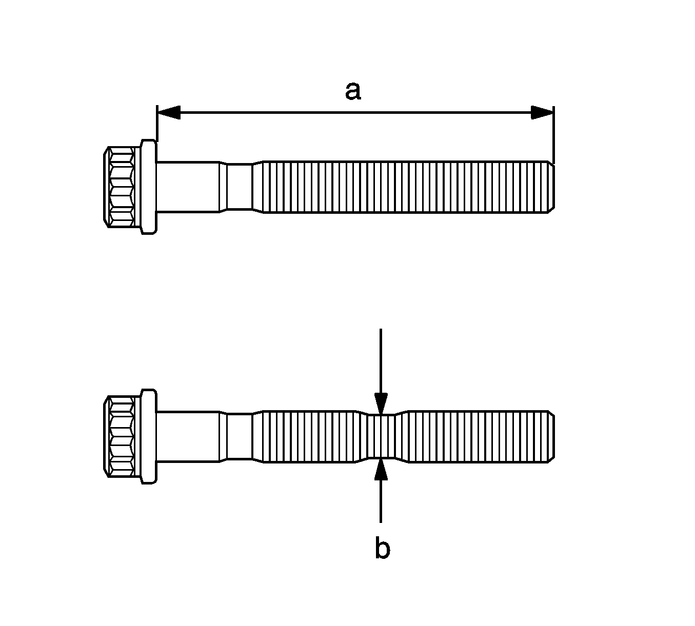
- Using vernier calipers, measure the tension portion diameter (a) of the bolts.
- If the bolt length is greater than the maximum, replace the bolt.
- Using vernier calipers, measure the minimum diameter (b) of the elongated thread at the measuring point.
- If the diameter is less than the minimum, replace the bolt.
- Check the oil nozzles for damage or clogging.
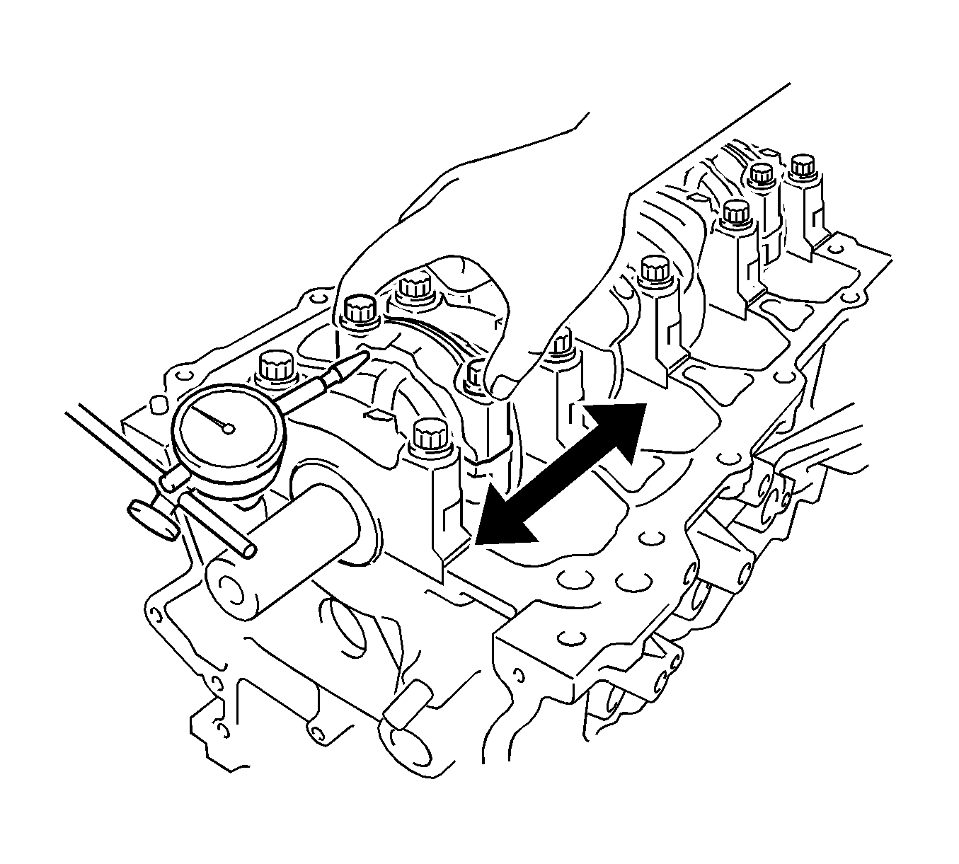
Specification
| • | Standard thrust clearance: 0.160-0.342 mm (0.0063-0.0135 in) |
| • | Maximum thrust clearance: 0.342 mm (0.0135 in) |
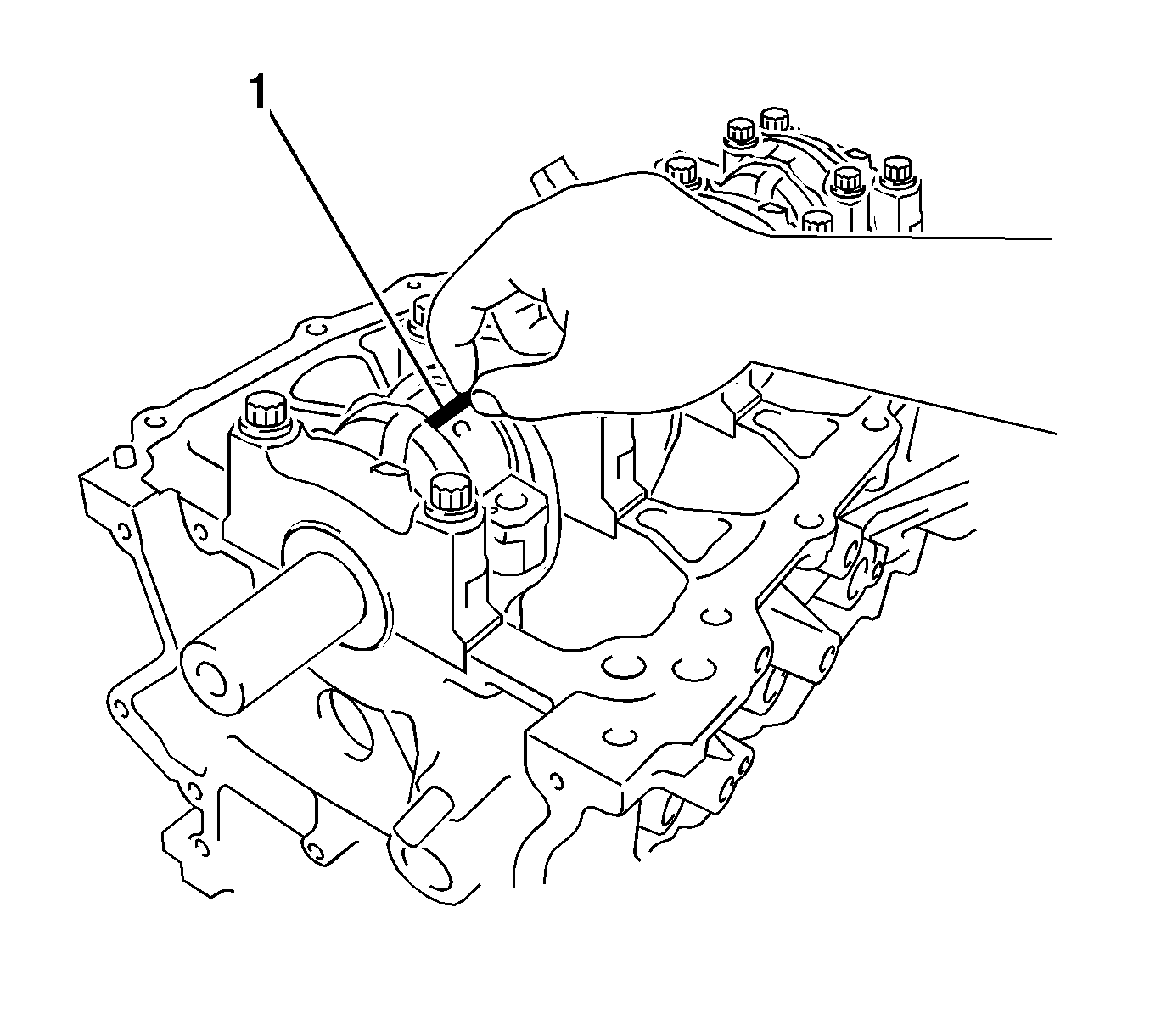
Note: Do not turn the crankshaft.
Specification
| • | Standard oil clearance: 0.030-0.062 mm (0.0012-0.0024 in) |
| • | Maximum oil clearance: 0.07 mm (0.0028 in) |
Note: Completely remove the Plastigage after the measurement.
If replacing a bearing, replace it with one that has the same number as its respective connecting rod cap. Each bearing standard thickness is indicated by a 1, 2, or 3 mark on its surface.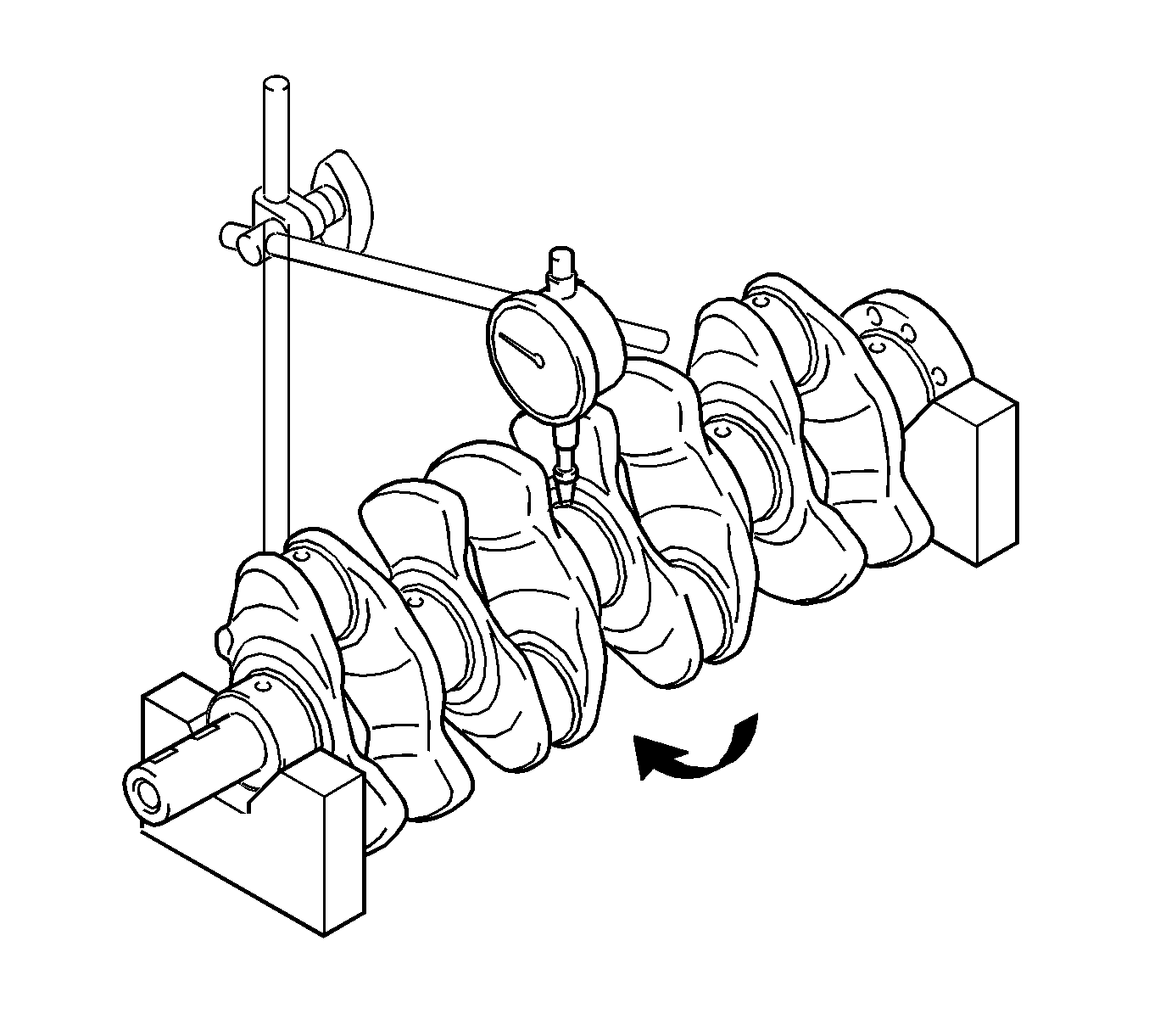
Specification
Maximum circle runout: 0.03 mm (0.0012 in)
Specification
Standard diameter: 47.988-48.000 mm (1.8893-1.8898 in)
Specification
Maximum taper and distortion: 0.004 mm (0.0002 in)
Specification
Standard diameter: 43.992-44.000 mm (1.7320-1.7323 in)
Specification
Maximum taper and distortion: 0.004 mm (0.0002 in)
Specification
| • | Standard thrust clearance: 0.04- 0.14 mm (0.0016-0.0055 in) |
| • | Maximum thrust clearance: 0.18 mm (0.0071 in) |
Note: The thrust washer thickness is 2.43-2.48 mm (0.0957-0.0976 in).
Note: A number is marked on each main bearing cap to indicate the installation position.
Note: Do not turn the crankshaft.
Specification
| • | Standard oil clearance: 0.016-0.039 mm (0.0006-0.0015 in) |
| • | Maximum oil clearance: 0.050 mm (0.0020 in) |
Note:
• Remove the Plastigage completely after the measurement. • If replacing a bearing, select a new one with the same number. If the number of the bearing cannot be determined, calculate the correct bearing number by adding together the numbers imprinted on the cylinder block and crankshaft. Then select a new
bearing with the calculated number according to the chart below. There are 4 sizes of standard bearings, marked 1, 2, 3 and 4 accordingly. • EXAMPLE: Cylinder block 3 + Crankshaft 5 = Total number 8 (Use bearing 3)
Specification
| • | Standard bolt length: 84.3-85.7 mm (3.3189-3.3740 in) |
| • | Maximum bolt length: 86.7 mm (3.4134 in) |
Note: Using a straightedge, visually check for thinner areas of the threaded part of the crankshaft bearing cap bolt.
Specification
| • | Standard outside diameter: 9.77-9.96 mm (0.3846-0.3921 in) |
| • | Minimum outside diameter: 9.1 mm (0.3583 in) |
Note: If there is damage or clogging, replace the oil nozzle.
