For 1990-2009 cars only
Special Tools
| • | J 2619-O1 Slide Hammer |
| • | J-46009 Front Axle Shaft Removal Tool |
Removal Procedure
Note: Prevent the seals (boots) from contacting the other components in order to prevent damage to the seals (boots).
- Raise and support the vehicle. Refer to Lifting and Jacking the Vehicle.
- Remove the tire and wheel assembly. Refer to Tire and Wheel Removal and Installation.
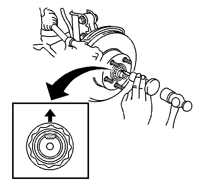
- Using a punch and a hammer, unstake the staked part of the lock nut.
- Remove the drive shaft lock nut.
- Remove the wheel speed sensor wire and brake hose retainer from the strut assembly.
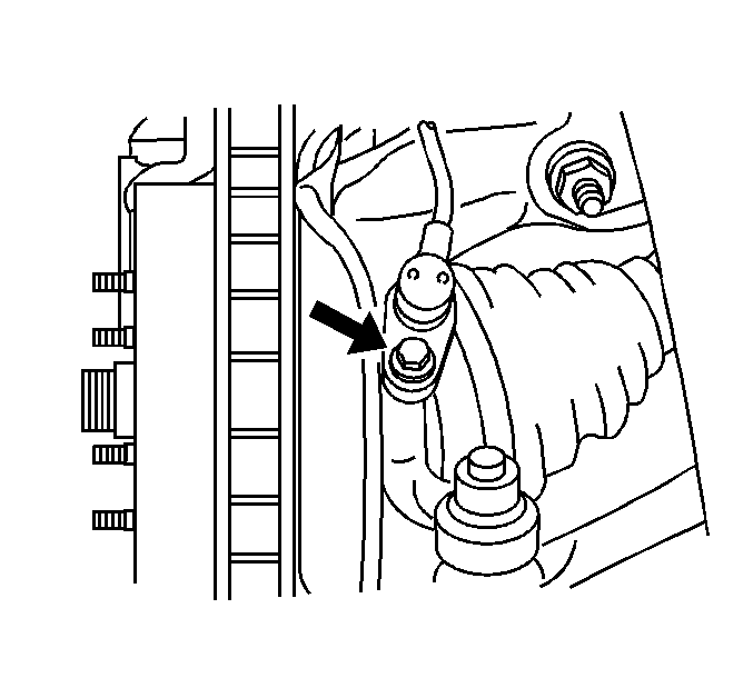
- Remove the wheel speed sensor from the steering knuckle.
- Disconnect the outer tie rod end from the steering knuckle.
- Disconnect the lower ball joint from the steering knuckle.
- Using a plastic hammer, disengage the wheel drive shaft from the wheel hub and bearing and support the wheel drive shaft.
- Using J-46009 and J 2619-01 remove the left side axle shaft from the transaxle.


Warning: Do not attempt to move vehicle with drive axle(s) removed from wheel bearing. Wheel(s) could fall off, dropping vehicle to the ground and causing personal injury or damage to the vehicle.
Installation Procedure
- Install the wheel drive shaft to the wheel hub and bearing.
- Connect the ball joint to the steering knuckle and tighten to 89 N·m (66 lb ft).
- Connect the outer tie rod end assembly to the steering knuckle and tighten to 49 N·m (36 lb ft).
- Install a NEW wheel drive shaft nut and tighten to 216 N·m (159 lb ft). Insert a drift or a flat-bladed tool through the caliper and into the brake rotor to prevent the rotor from turning.
- Using a punch and hammer, stake the locknut.
- Install the wheel speed sensor and tighten the retaining bolt to 8 N·m (71 lb in).
- Install the tire and wheel assembly. Refer to Tire and Wheel Removal and Installation.
- On AWD models, inspect the transfer case fluid level.
- Lower the vehicle.
- Inspect the transaxle fluid level.
Note: Prevent the boots from contacting other components to prevent damage to the boots.


