For 1990-2009 cars only
Removal Procedure
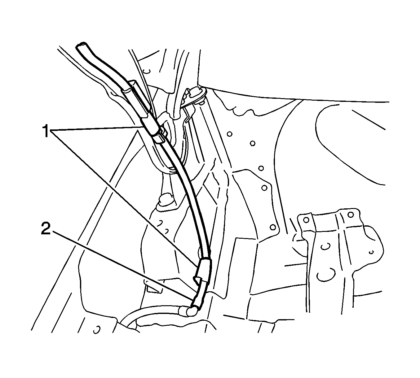
- Disconnect the washer hose clamps (1) and washer hose (2).
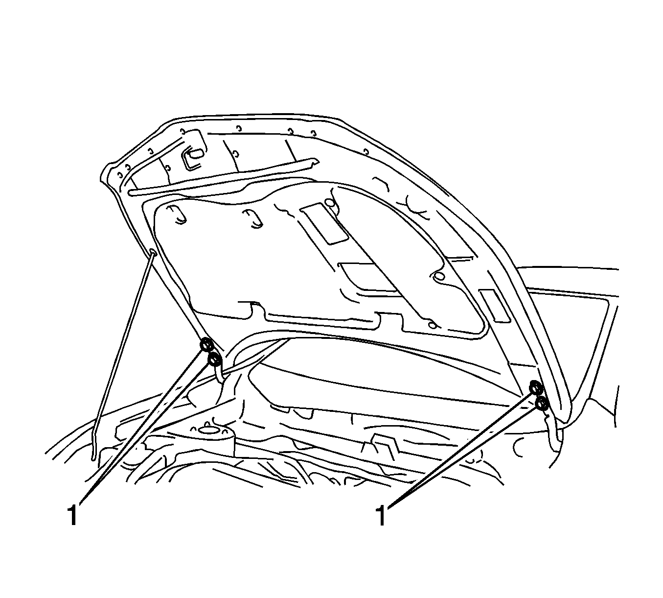
- Remove the bolts (1) and hood sub-assembly.
- Remove the air inlet grill panel. Refer to Air Inlet Grille Panel Replacement.
- Align the front wheels facing straight ahead.
- Remove the front wheels. Refer to Tire and Wheel Removal and Installation.
- Remove the engine splash shields. Refer to Engine Splash Shield Replacement - Left Side, Engine Splash Shield Replacement - Right Side.
- Drain the manual transaxle oil.
- Remove the engine cover assembly. Refer to Engine Cover Replacement.
- Remove the air cleaner assembly.
- Remove the battery. Refer to Battery Replacement.
- Remove the battery tray. Refer to Battery Tray Replacement.
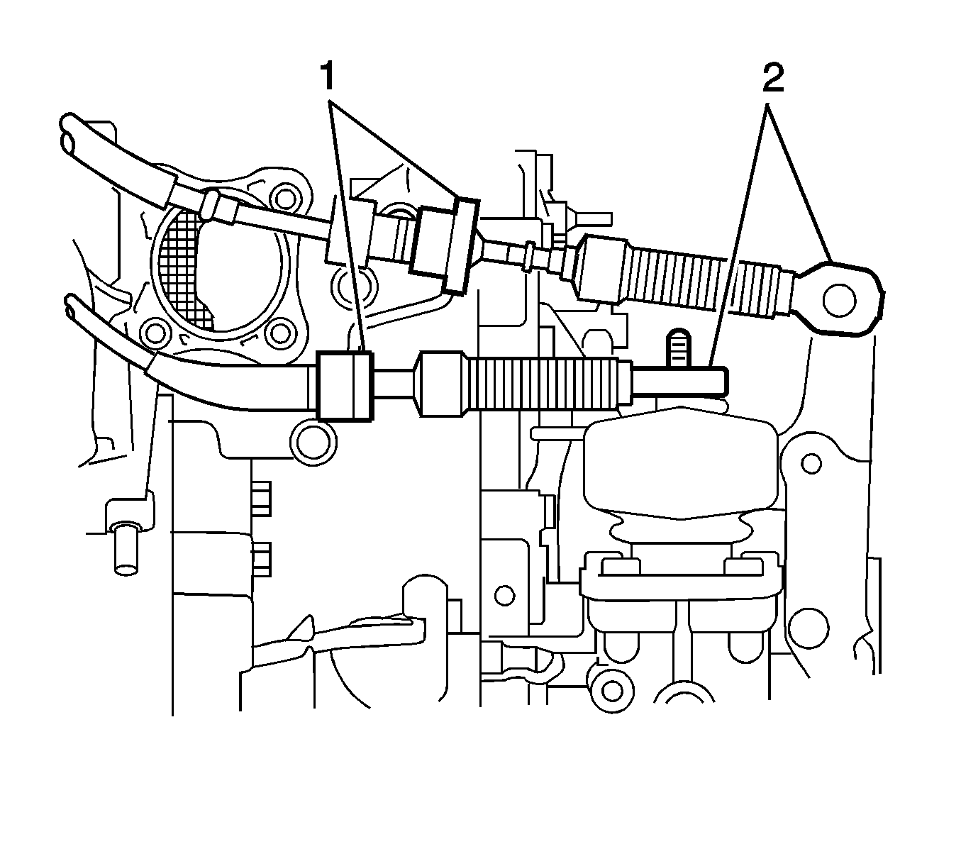
- Remove the clips and disconnect the transmission shift lever cables from the control cable bracket (1).
- Remove the clips and disconnect the transmission cables from the transaxle (2).
- Remove the clutch release cylinder assembly.
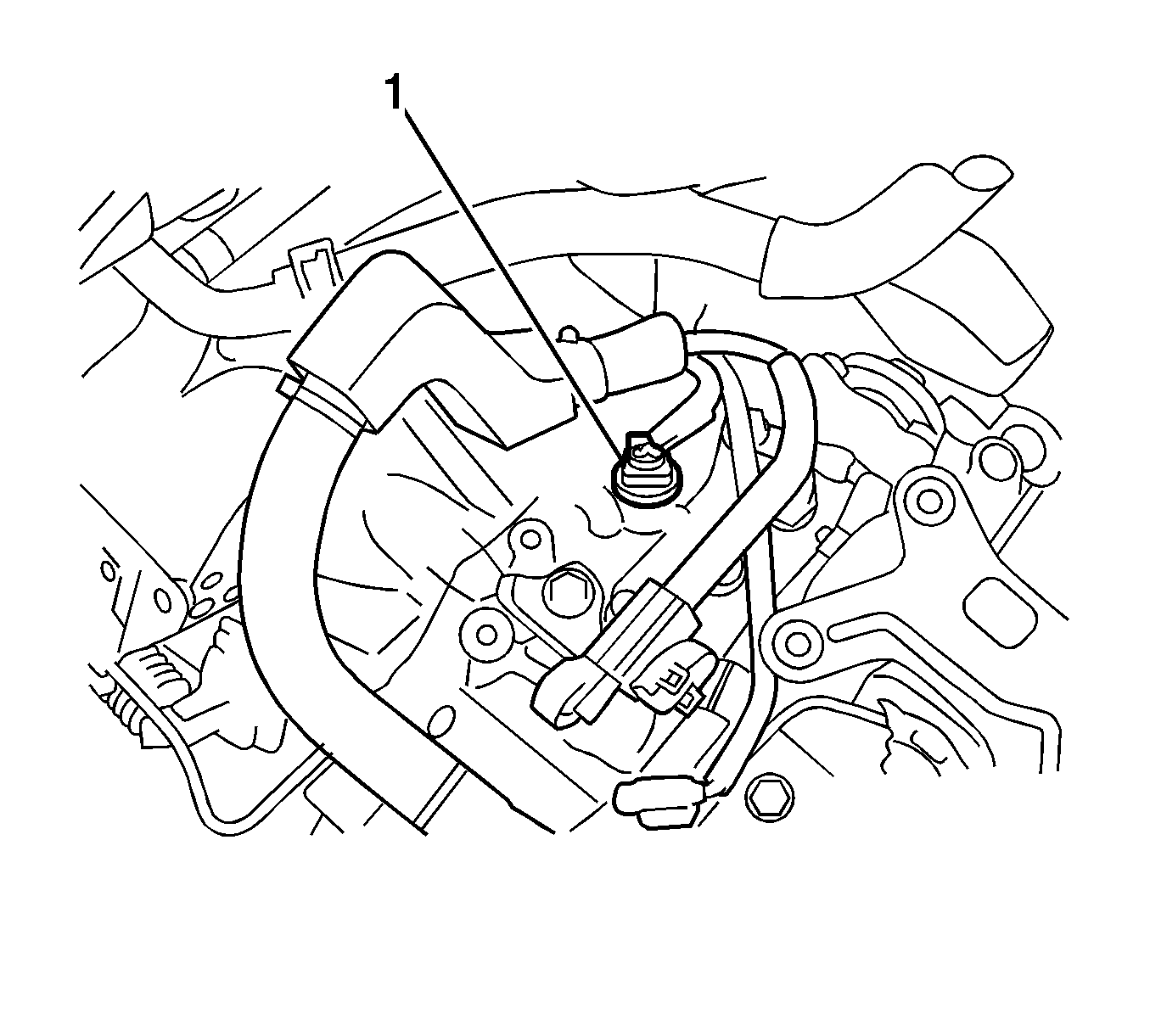
- Disconnect the back-up light switch connector (1) and wire harness clamp and wire harness.
- Remove the front suspension crossmember. Refer to Front Suspension Crossmember Replacement.
- Remove the front engine mounting insulator.
- Remove the starter assembly. Refer to Starter Replacement.
- Remove the nut (1), and disconnect the wire harness clamp and wire harness.
- Support the manual transaxle with a transmission jack.
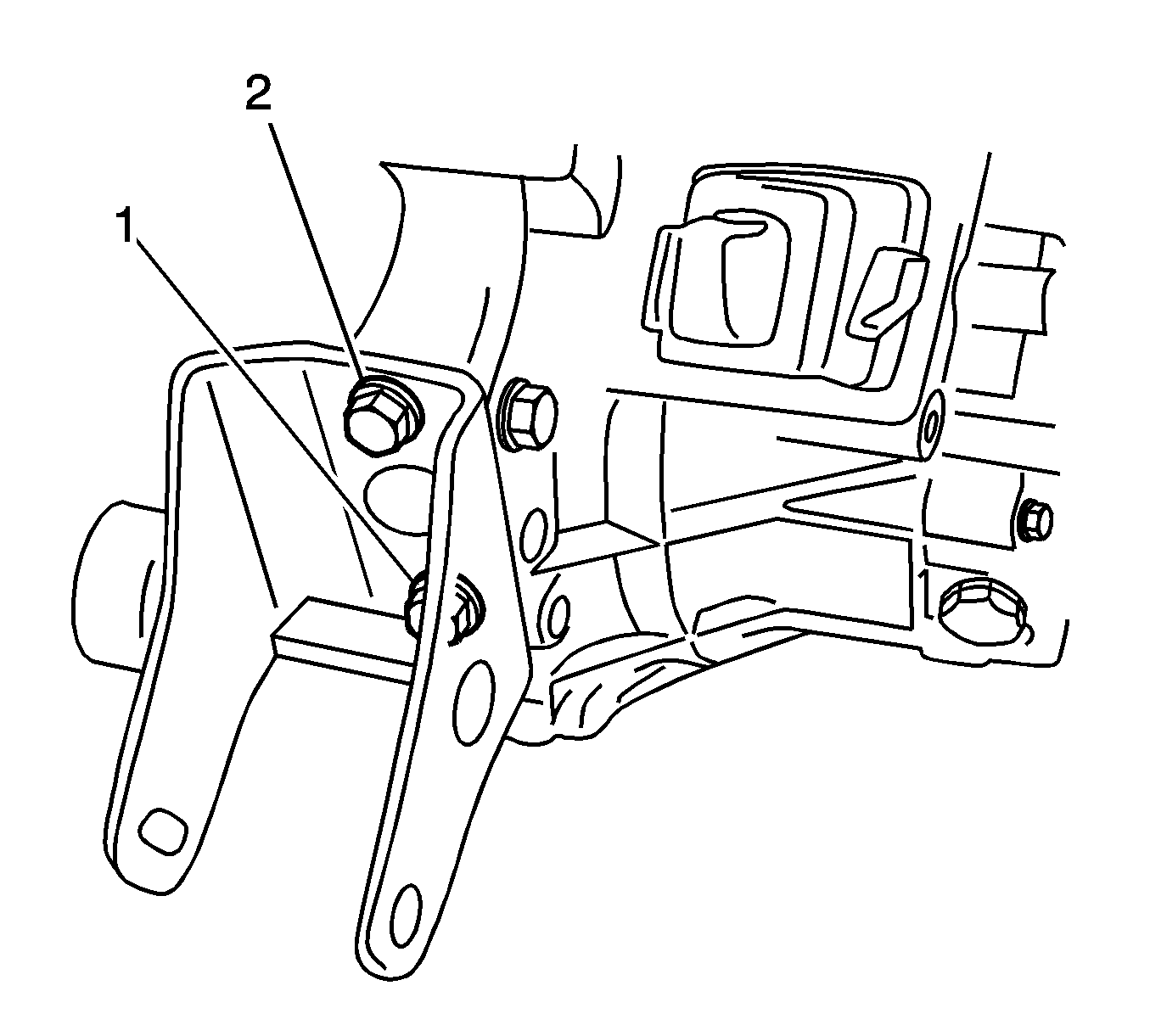
- Remove the bolt (1) and wire harness clamp bracket.
- Remove the through bolt (2) and nut, then separate the engine mounting insulator sub-assembly LH.
- Tilt the manual transaxle downward.
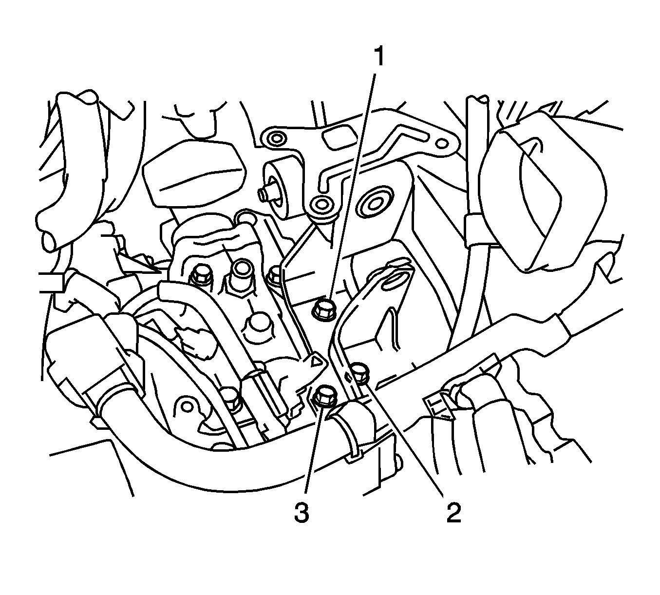
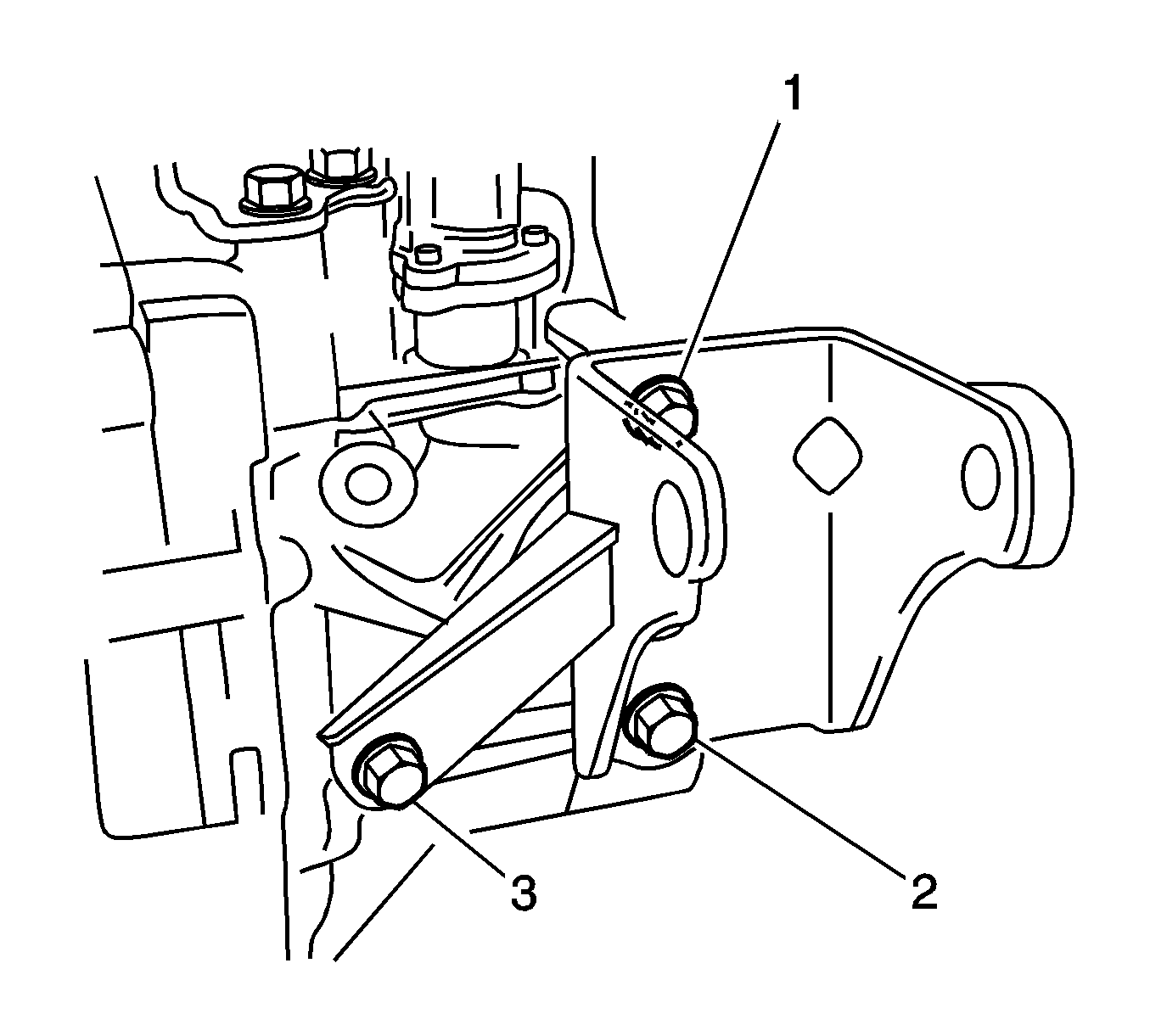
- Remove the bolts (1-3) and the engine mounting bracket LH.
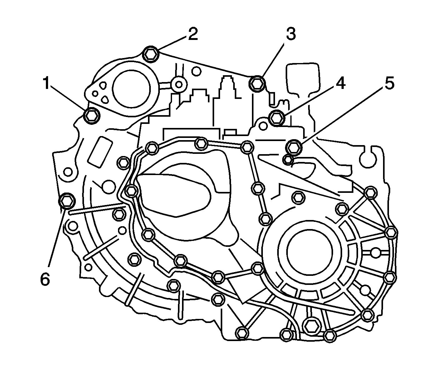
- Remove the bolts (1-6).
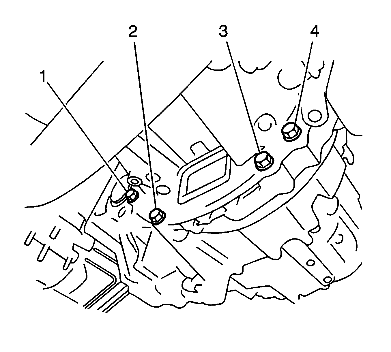
- Remove the bolts (1-4) and the manual transaxle.
- Remove the bolts (1, 2) and the front engine mounting bracket.
- Remove the rear engine mounting insulator.
- Remove the bolts (1-3) and the rear engine mounting bracket.
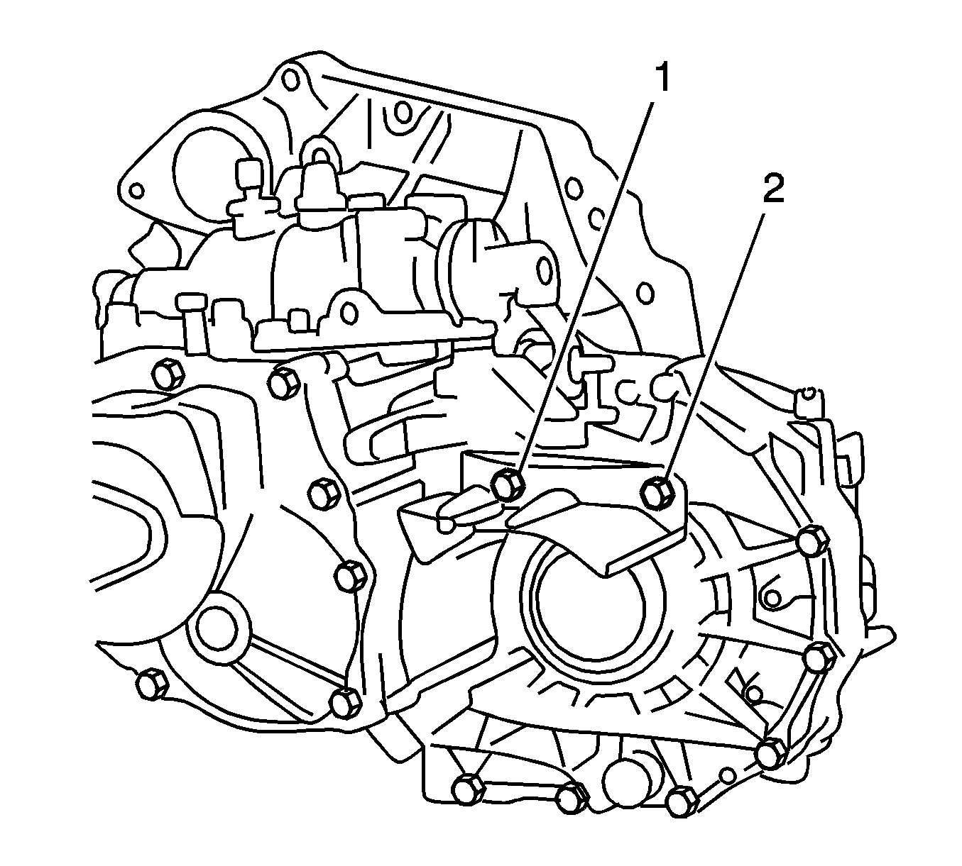
- Remove the bolts (1, 2) and the manual transmission case protector.
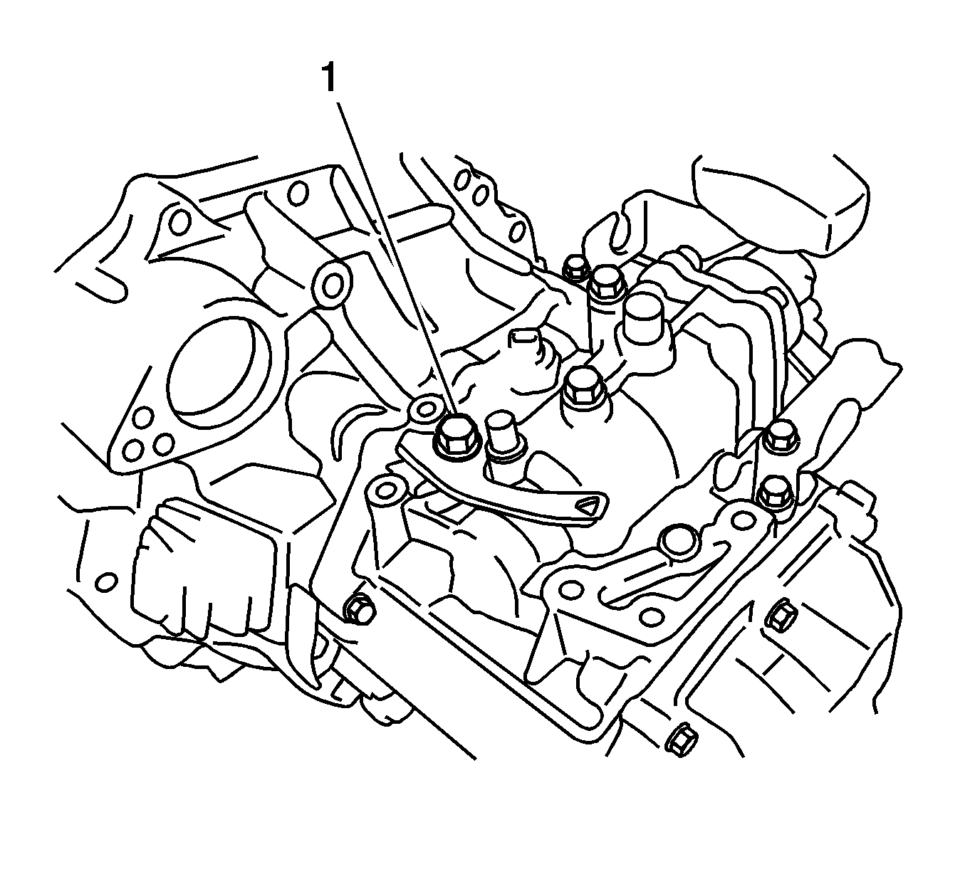
- Remove the bolt (1) and wire harness clamp bracket.
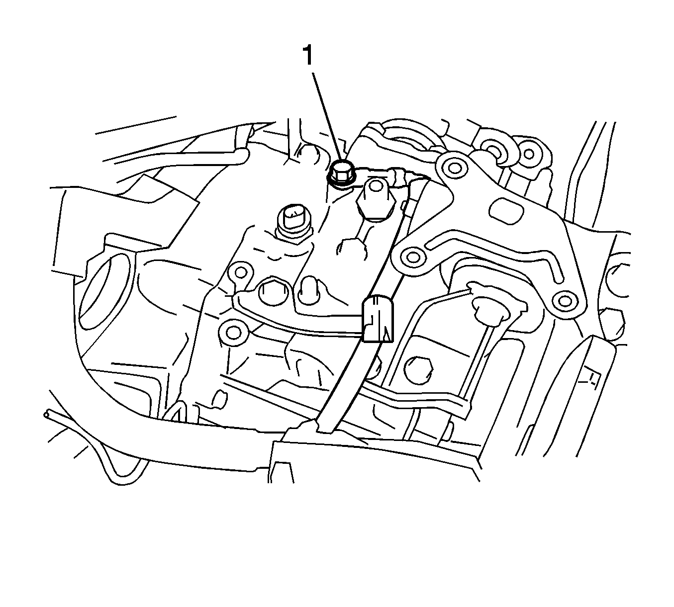
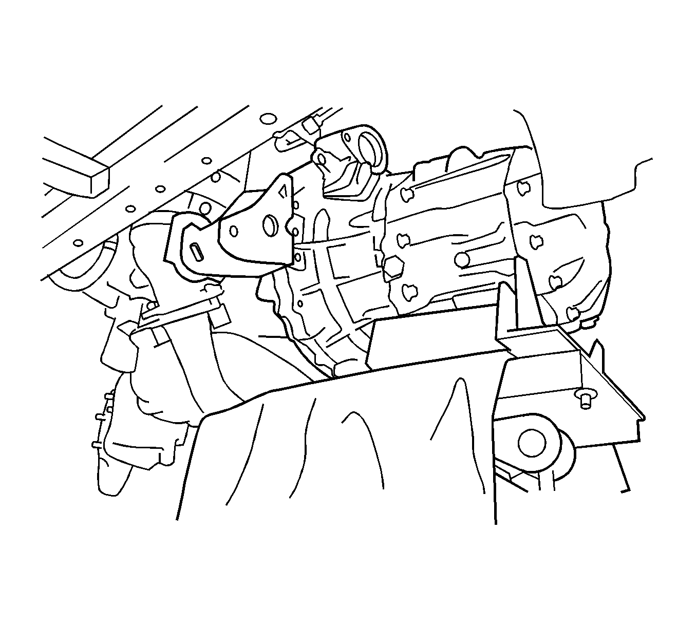
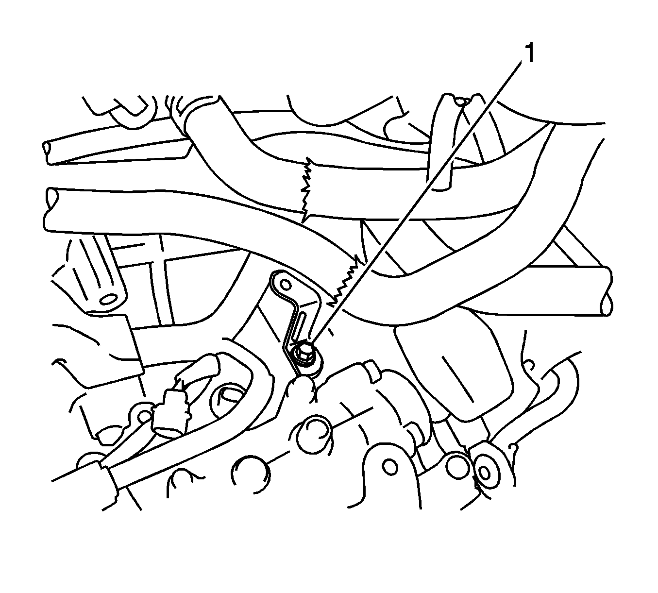
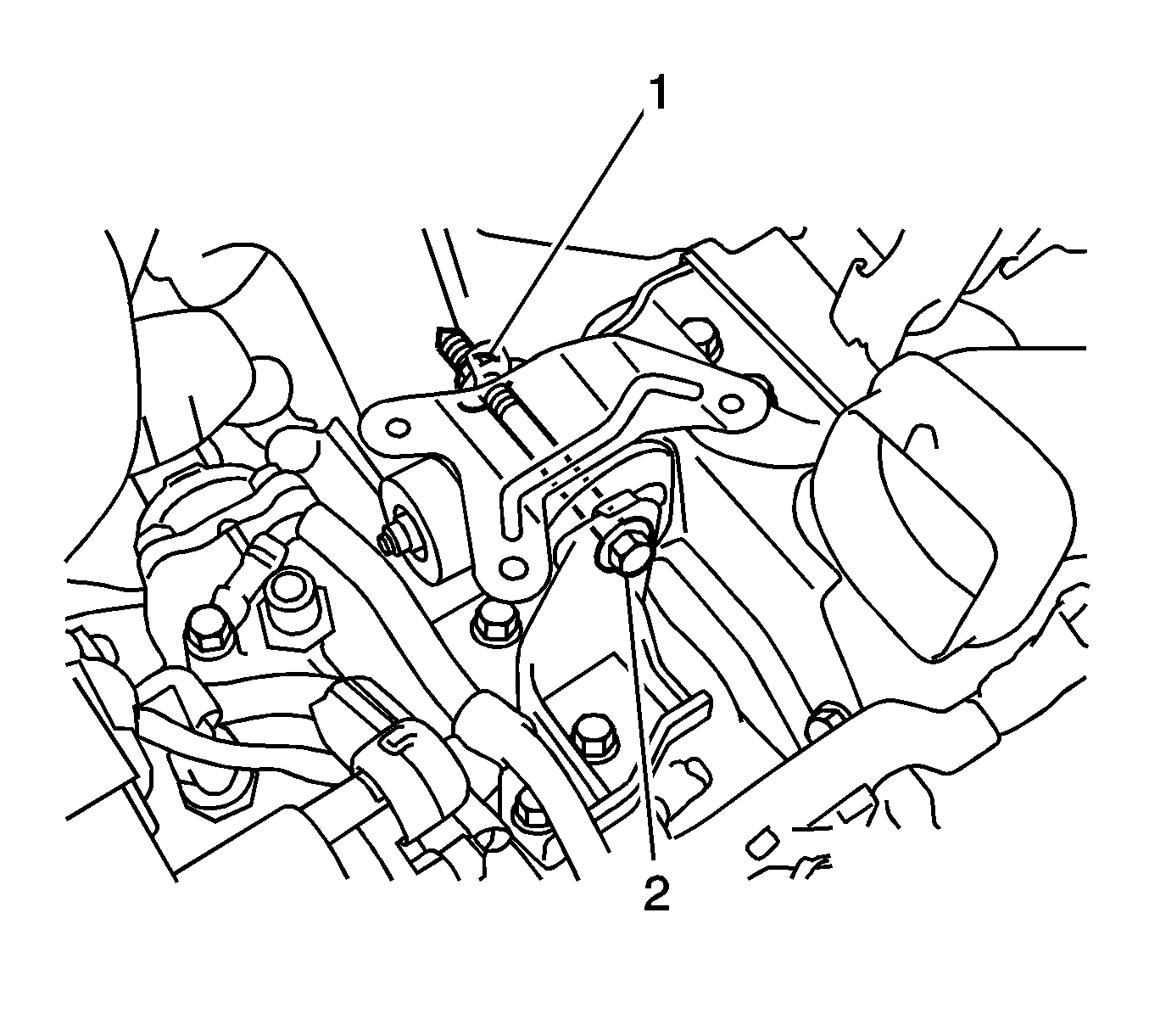
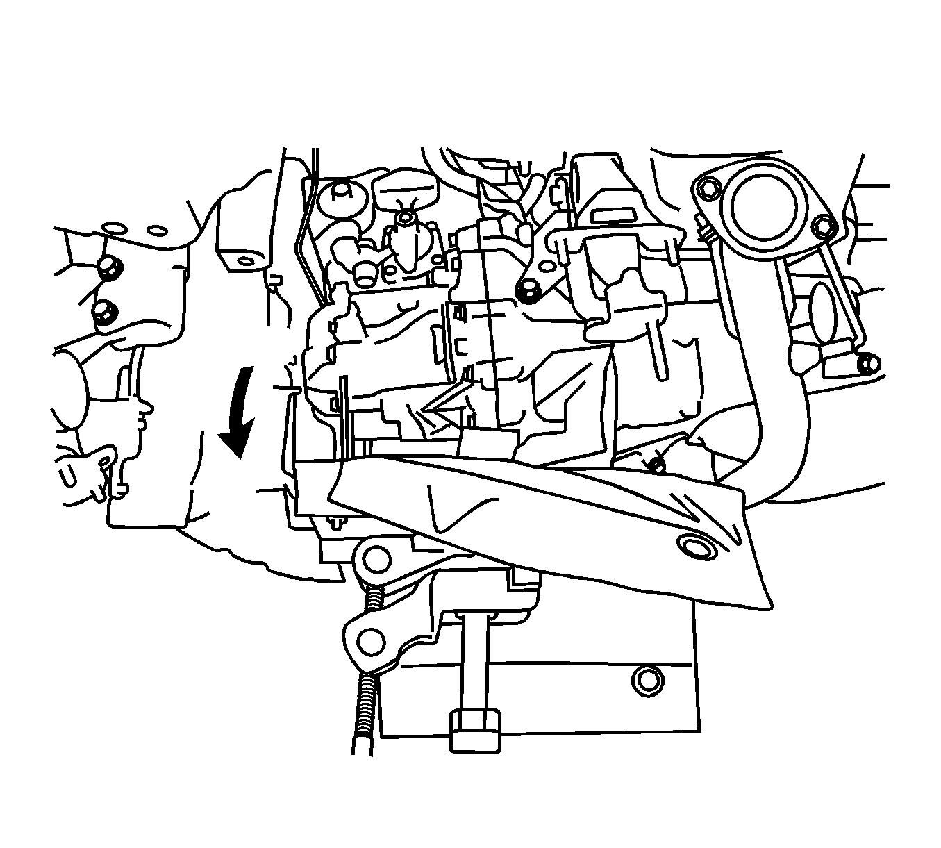
Note: Take care so that the rear side of the engine assembly does not come into contact with the body.
Installation Procedure
- Install the wire harness clamp bracket with the bolt (1) and tighten to 26 N·m (19 lb ft).
- Install the manual transmission case protector with the bolts (1, 2) and tighten to 18 N·m (13 lb ft).
- Install the rear engine mounting bracket with the bolts (1-3) and tighten to 45 N·m (33 lb ft).
- Install the rear engine mounting insulator.
- Install the front engine mounting bracket with the bolts (1, 2) and tighten to 64 N·m (47 lb ft).
- Align the input shaft with the clutch disc and install the manual transaxle onto the engine.
- Install the bolts (1-4) and tighten.
- Install the bolts (1-4) and tighten to 44 N·m (32 lb ft).
- Hand tighten the engine mounting bracket LH bolts.
- Tighten the bolts (1-3) to 52 N·m (38 lb ft).
- Install the engine mounting insulator sub-assembly LH with the through bolt (2) and nut and tighten to 56 N·m (41 lb ft).
- Install the wire harness clamp with the bolt (1) and tighten to 13 N·m (9 lb ft).
- Install the wire harness with the bolt (1) and tighten to 13 N·m (9 lb ft).
- Connect the wire harness to the wire harness clamp.
- Install the starter assembly. Refer to Starter Replacement
- Install the front engine mounting insulator.
- Install the front suspension crossmember assembly. Refer to Front Suspension Crossmember Replacement
- Connect the wire harness to the wire harness clamp.
- Connect the back-up light switch connector (1).
- Install the clutch release cylinder assembly.
- Install the transmission shift lever cables to the control cable bracket with new clips (1).
- Install the transmission cables to the transaxle with the clips (2).
- Install the battery tray. Refer to Battery Tray Replacement.
- Install the battery. Refer to Battery Replacement.
- Install the air cleaner assembly.
- Install the air inlet grill panel. Refer to Air Inlet Grille Panel Replacement.
- Install the hood assembly with the bolts (1) and tighten to 13 N·m (10 lb ft).
- Install the washer hose (2) and washer hose clamps.
- Bleed the clutch line.
- Add transaxle oil.
- Inspect and adjust the transaxle oil.
- Install the engine splash shields. Refer to Engine Splash Shield Replacement - Left Side, Engine Splash Shield Replacement - Right Side.
- Install the front wheels. Refer to Tire and Wheel Removal and Installation.
- Adjust the front wheel alignment. Refer to Wheel Alignment Measurement.
- Install the engine cover. Refer to Engine Cover Replacement.
Caution: Refer to Fastener Caution in the Preface section.


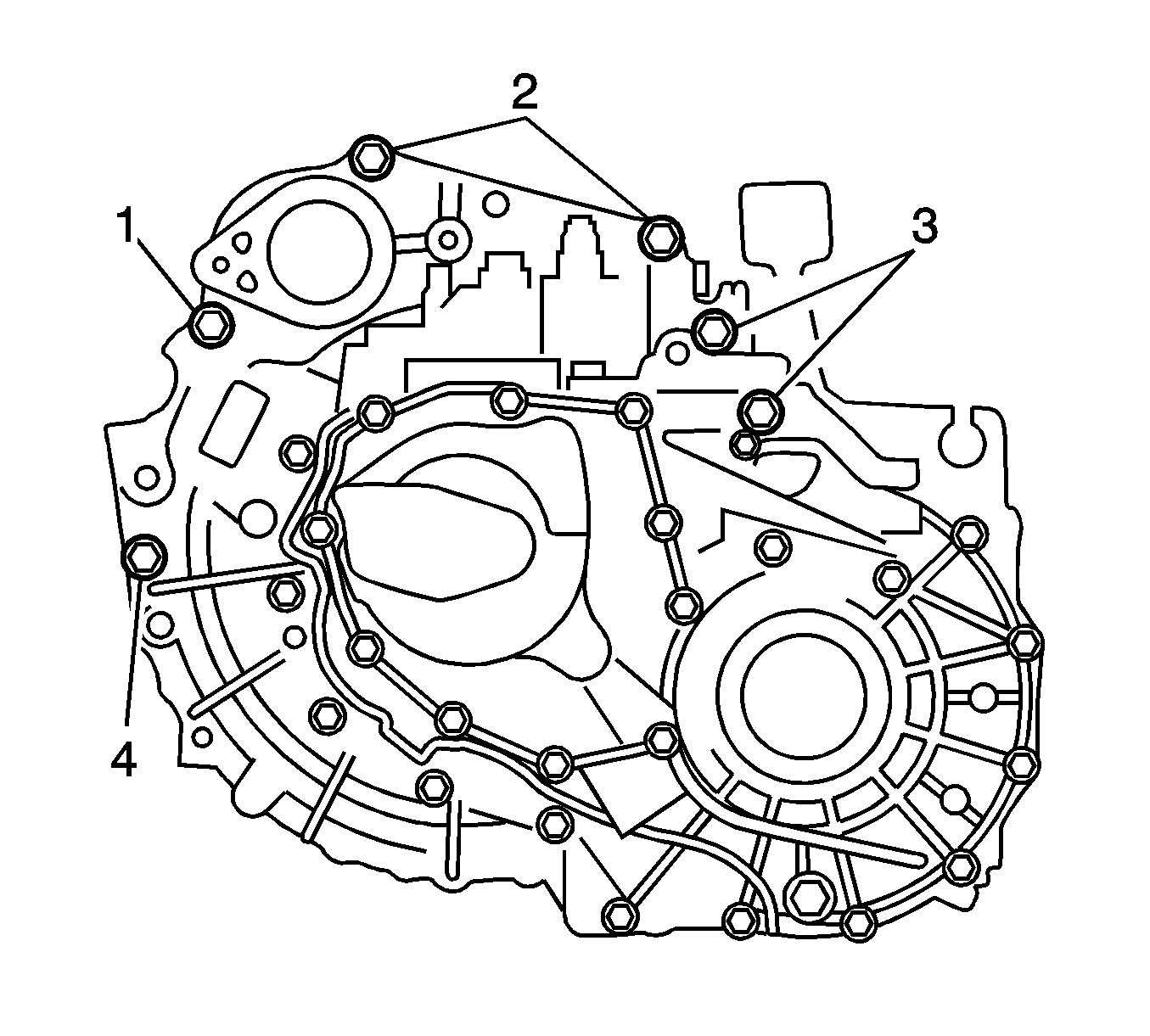
Note: Insert dowel pins into the dowel holes securely so that the end face of the transaxle assembly fits close against the engine assembly before tightening the bolts.
| • | Bolt (1) to 64 N·m (47 lb ft) |
| • | Bolts (2) to 64 N·m (47 lb ft) |
| • | Bolts (3) to 46 N·m (34 lb ft) |
| • | Bolt (4) to 46 N·m (34 lb ft) |


