For 1990-2009 cars only
- Disconnect the negative battery cable. Refer to Battery Negative Cable Disconnection and Connection.
- Install the engine support fixture. Refer to Engine Support Fixture.
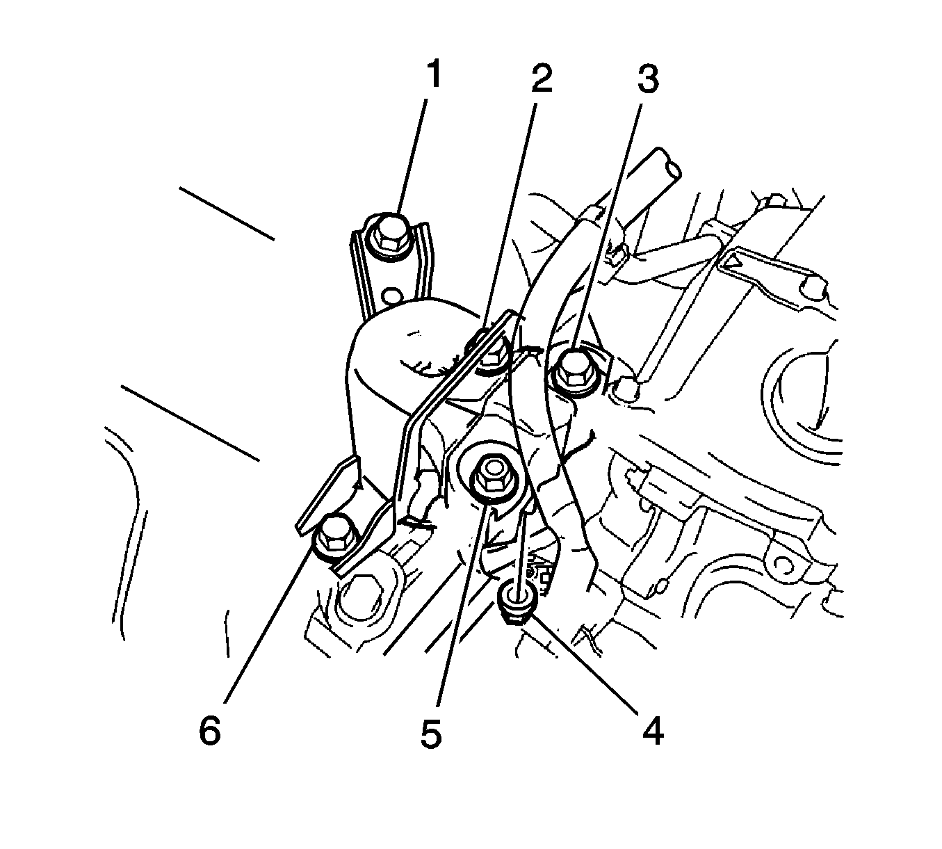
- Remove the 4 bolts (1, 2, 3, 6) and 2 nuts (4, 5), then remove the right engine mounting insulator.
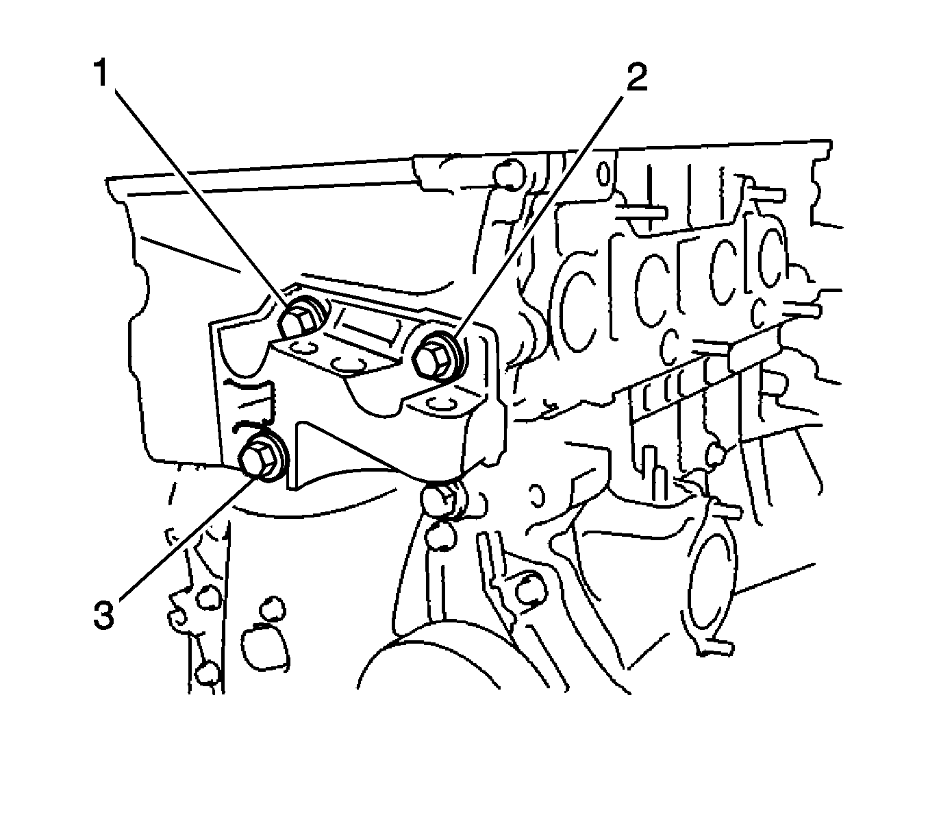
- Remove the 3 bolts (1, 2, 3) and transverse engine mounting bracket.
Warning: Refer to Battery Disconnect Warning in the Preface section.

Note: Do not apply excessive force to the return tube when removing the right engine mounting insulator sub-assembly.
Note: Keep clearance by lowering the engine using the engine support fixture when removing the front engine mounting insulator.

Installation Procedure
- Install the engine transverse engine mounting bracket with the 3 bolts (1, 2, 3) and tighten to 55 N·m (41 lb ft).
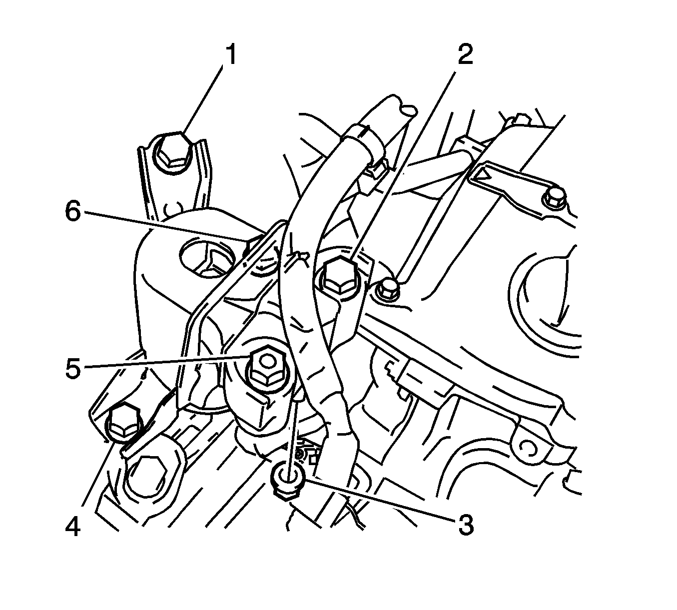
- Install the right engine mounting insulator sub-assembly with the 4 bolts (1, 2, 4, 6) and 2 nuts (3, 5) and tighten
- Remove the engine support fixture.
- Connect the negative battery cable. Refer to Battery Negative Cable Disconnection and Connection.
Caution: Refer to Fastener Caution in the Preface section.


| • | Bolts 1, 4 and 6 to 52 N·m (38 lb ft) |
| • | Bolt 2 to 95 N·m (70 lb ft) |
| • | Nut 5 to 95 N·m (70 lb ft) |
| • | Nut 3 to 52 N·m (38 lb ft) |
