For 1990-2009 cars only
Notice: Always connect or disconnect the wiring harness connector from the EBCM/EBTCM with the ignition switch in the OFF position. Failure to observe this precaution could result in damage to the EBCM/EBTCM.
Removal Procedure
- Turn the ignition switch to the OFF position.
- Clean the electronic brake control module (EBCM) to brake pressure modulator valve (BPMV) area of any accumulated dirt and foreign material.
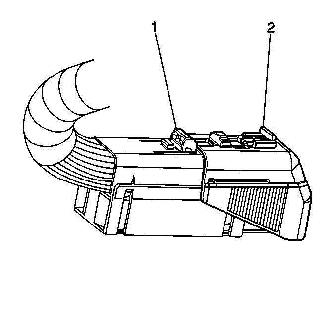
- Disengage the electrical connector position assurance (CPA) locking tab (1) from the connector sliding cover lock tab.
- Depress the cover lock tab, then move the sliding connector cover (2) to the open position.
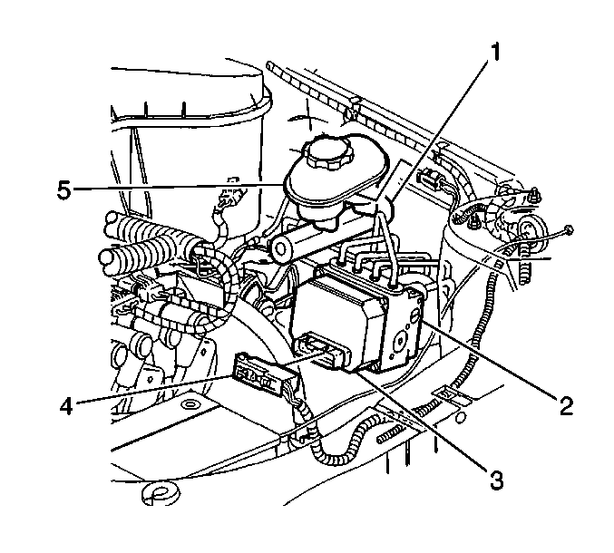
- Disconnect the electrical harness connector (4) from the EBCM (3).
- Remove the 4 EBCM-to-BPMV retaining bolts.
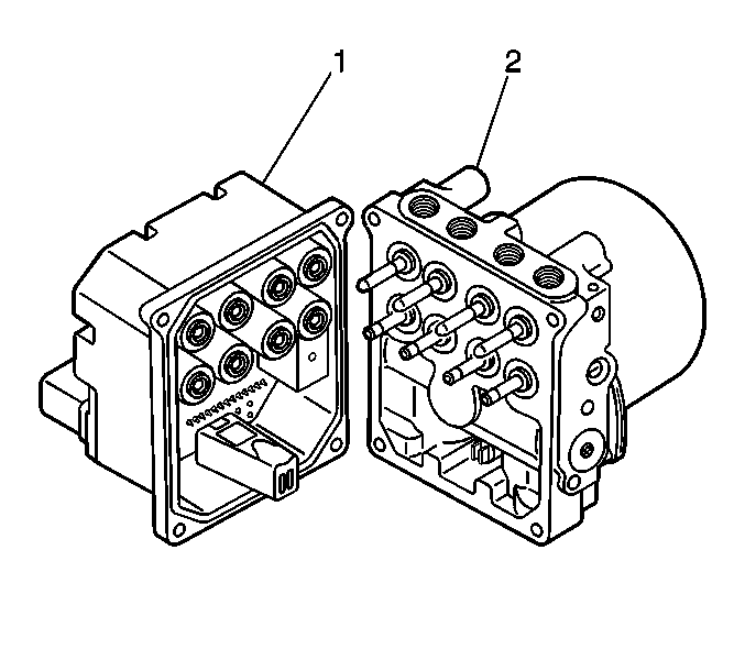
- Separate the EBCM (1) from the BPMV (2) by carefully pulling apart.


Important:
• Do not pry apart the EBCM (1) from the BPMV (2) using a
tool. Be careful not to damage seal on the EBCM or the mating surface of the BPMV. • Care must be taken not to damage the solenoids when the EBCM is removed
from the BPMV.
Installation Procedure
- Clean the sealing surface of the BPMV, with denatured alcohol and a clean shop cloth.
- If the EBCM that was removed is being reinstalled, clean the seal and sealing surface of the EBCM, with denatured alcohol and a clean shop cloth.
- Install the EBCM (1) to the BPMV (2). Use care when aligning the EBCM to the BPMV electrical terminals.
- Install the 4 EBCM-to-BPMV retaining bolts. Tighten the bolts in a criss-cross pattern.
- Connect the electrical harness connector (4) to the EBCM (3).
- Depress the cover lock tab, then move the sliding connector cover (2) to the home position to lock.
- Engage the electrical connector CPA locking tab (1) to the connector sliding cover lock tab.
- Perform the ABS Diagnostic System Check. Refer to Diagnostic System Check - ABS .

Notice: Refer to Fastener Notice in the Preface section.
Tighten
Tighten the bolts to 5 N·m (44 lb in).


Important: Do NOT start the engine, but only turn the ignition switch to the ON position.
