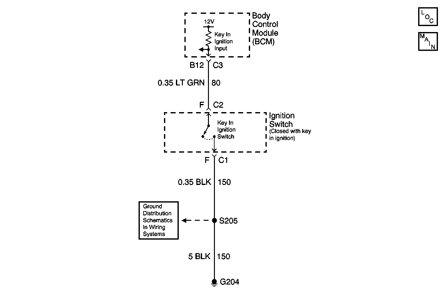
Circuit Description
The BCM receives a ground signal from the ignition switch through the key-in ignition input circuit when the key is in the ignition. The BCM monitors the key-in ignition circuit in order to determine if the ignition key is in the ignition switch.
Conditions for Running the DTC
| • | The accessory input is active for 30 seconds. |
| • | Voltage supplied to the BCM is in the normal operating range (approximately 9-16 volts). |
Conditions for Setting the DTC
The KEY-IN IGNITION input to the BCM is not active.
Action Taken When the DTC Sets
| • | The BCM assumes the KEY-IN IGNITION input to be active. |
| • | The BCM stores DTC B2965 in memory. |
Conditions for Clearing the DTC
| • | A current DTC B2965 will clear when the code setting condition is no longer present. |
| • | All BCM history codes clear after 100 ignition cycles (from OFF to ON) with no current codes active during the 100 ignition cycles. |
Diagnostic Aids
| • | Inspect the wiring and connections to the ignition switch and BCM. |
| • | If the DTC is a history DTC, the problem may be intermittent. Perform the above tests while wiggling the wiring and connectors. This may often cause the malfunction to appear. |
Test Description
The number(s) below refer to the step number(s) on the diagnostic table.
-
The scan tool will display YES when the ignition key is inserted into the ignition switch.
-
The scan tool will display NO when the ignition key is removed from the ignition switch.
-
This step tests for a short to ground in circuit 80.
Step | Action | Yes | No | ||||
|---|---|---|---|---|---|---|---|
1 | Did you perform the Body Control Module Diagnostic System Check? | Go to Step 2 | |||||
Does the scan tool display YES? | Go to Step 3 | Go to Step 4 | |||||
While observing the KEY-IN IGNITION parameter on the scan tool, remove and reinsert the ignition key. Does the KEY-IN IGNITION parameter change state? | Go to Testing for Intermittent Conditions and Poor Connections in Wiring Systems | Go to Step 6 | |||||
4 |
Is ground present at the terminal? | Go to Step 8 | Go to Step 5 | ||||
5 | Refer to Circuit Testing and Wiring Repairs in Wiring Systems in order to test the following circuits for an open:
Was a condition found and corrected? | Go to Step 12 | Go to Step 9 | ||||
Does the scan tool display YES? | Go to Step 7 | Go to Step 9 | |||||
7 | Test the signal circuit of the ignition switch for a short to ground. Refer to Circuit Testing and Wiring Repairs in Wiring Systems. Did you find and correct the condition? | Go to Step 12 | Go to Step 8 | ||||
8 | Inspect for poor connections at the harness connector of the body control module. Refer to Testing for Intermittent Conditions and Poor Connections and Connector Repairs in Wiring Systems. Did you find and correct the condition? | Go to Step 12 | Go to Step 10 | ||||
9 | Inspect for poor connections at the harness connector of the ignition switch. Refer to Testing for Intermittent Conditions and Poor Connections and Connector Repairs in Wiring Systems. Did you find and correct the condition? | Go to Step 12 | Go to Step 11 | ||||
10 |
Important: Perform the setup procedure for the body control module. Refer to Body Control Module (BCM) Programming/RPO Configuration . Replace the body control module. Refer to Body Control Module Replacement . Did you complete the replacement? | Go to Step 12 | -- | ||||
11 | Replace the ignition switch. Refer to Ignition Lock Cylinder Replacement - On Vehicle in Steering Wheel and Column. Did you complete the replacement? | Go to Step 12 | -- | ||||
12 |
Does the DTC reset? | Go to Step 2 | System OK |
