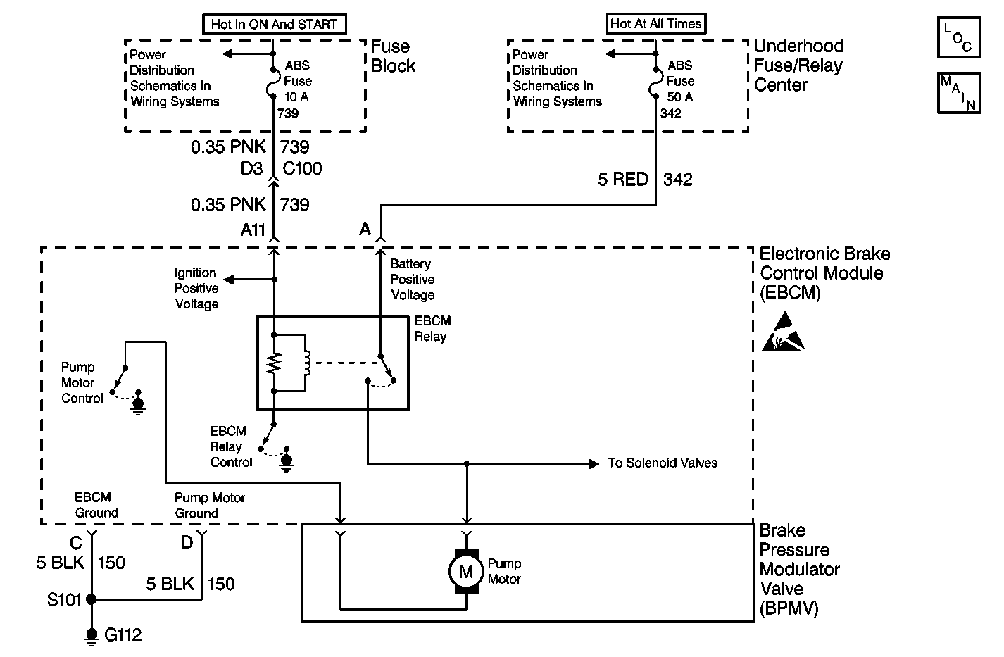
Circuit Description
The EBCM contains a data storage area called Keep Alive Memory (KAM) which can save pertinent data when the ignition is turned OFF. The KAM data is lost if battery power or module ground is removed from the EBCM. The KAM is an integral part of the EBCM and cannot be serviced separately.
Conditions for Running the DTC
ABS and ETS conditions are normal.
Conditions for Setting the DTC
DTC C1254 is set when 4 running resets occur. A running reset occurs when the vehicle is running and functions are normal then suddenly there is a loss of power or ground connection to the EBCM.
Action Taken When the DTC Sets
The following actions will occur:
| • | The EBCM stores a malfunction DTC. |
| • | The EBCM disables ABS and ETS. |
| • | The ABS warning indicator turns ON. |
| • | The TRAC OFF indicator turns ON. |
| • | The EBCM will disable the transmission of class 2 functional messages. |
Conditions for Clearing the DTC
| • | The Condition for setting the DTC is no longer present and the scan tool Clear DTCs function is used. |
| • | The EBCM automatically clears the history DTC when a current DTC is not detected in 100 consecutive drive cycles. |
Diagnostic Aids
Possible causes for DTC C1254 to set are:
| • | Running reset occurred. |
| • | Loss of EBCM ground. |
| • | Sudden drop in system voltage to less than 5 volts. |
| • | Poor or loose ground connections. |
| • | Poor or loose power connections. |
| • | Battery disconnected due to corrosion or loose battery terminals. |
| • | An internal EBCM malfunction exists. |
It is very important that a thorough inspection of the wiring and connectors be performed. Failure to carefully and fully inspect wiring and connectors may result in misdiagnosis, causing part replacement with reappearance of the malfunction.
Test Description
The numbers below refer to the step numbers on the diagnostic table.
-
This step ensures that ignition positive voltage is being received by the EBCM.
-
This step ensures that battery positive voltage is being received by the EBCM.
Step | Action | Value(s) | Yes | No |
|---|---|---|---|---|
1 | Did you perform the ABS Diagnostic System Check? | -- | Go to Step 2 | |
Does the scan tool indicate that the Ignition Voltage parameter is greater than the specified value? | 10.5 V | Go to Step 3 | Go to Step 5 | |
With the scan tool, observe the Switched Battery Voltage parameter in the ABS data list. Does the scan tool indicate that the Switched Battery Voltage parameter is greater than the specified value? | 10.5 V | Go to Step 4 | Go to Step 6 | |
4 | Test the charging system. Refer to Diagnostic System Check - Charging System in Engine Electrical. Did you find and correct the condition? | -- | Go to Step 10 | Go to Step 7 |
5 |
Did you find and correct the condition? | -- | Go to Step 10 | Go to Step 7 |
6 |
Did you find and correct the condition? | -- | Go to Step 10 | Go to Step 7 |
7 | Test the ground circuit of the EBCM for a high resistance or an open. Refer to Circuit Testing and Wiring Repairs in Wiring Systems. Did you find and correct the condition? | -- | Go to Step 10 | Go to Step 8 |
8 | Inspect for poor connections/terminal tension at the EBCM harness connector. Refer to Testing for Intermittent Conditions and Poor Connections and Connector Repairs in Wiring Systems. Did you find and correct the condition? | -- | Go to Step 10 | Go to Step 9 |
9 | Replace the EBCM. Refer to Electronic Brake Control Module Replacement . Did you complete the replacement? | -- | Go to Step 10 | -- |
10 |
Does the DTC reset? | -- | Go to Step 2 | System OK |
