The fuel metering system is made up of the following parts:
| • | Fuel supply components (fuel tank, pump, and lines) |
| • | Fuel pump electrical circuit |
| • | Fuel rail assembly, including: |
| - | Fuel pressure regulator |
| • | Throttle body assembly, including: |
| - | Idle air control (IAC) valve |
| - | Throttle position (TP) sensor |
Accelerator Controls
The accelerator control system is a cable type and there are no linkage
adjustments. Therefore, the only specific cable for each application must
be used. When work has been performed on the accelerator controls, always
make sure that all components are installed correctly and that the linkage
and cables are not rubbing or binding in any manner. The throttle should
operate freely without binding between full closed and wide open throttle
(WOT).
Fuel Injectors

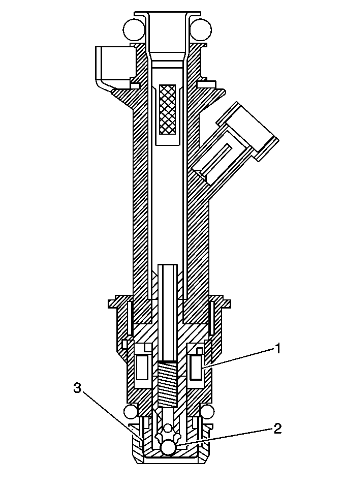
The fuel injector assembly
is a solenoid-operated device, controlled by the PCM, that meters pressurized
fuel to a single engine cylinder. The PCM energizes the
fuel injector solenoid (1) which opens a ball valve (2)
allowing fuel to flow past the ball valve, and through a director plate
(3) at the injector outlet. The director plate has machined
holes that control the fuel flow, generating a conical spray
pattern of finely atomized fuel at the injector tip. Fuel
from the tip is directed at the intake valve, causing it
to become further atomized and vaporized before entering the
combustion chamber. A fuel injector that is stuck partly open would
cause loss of pressure after the engine is shut down, so
long crank times would be noticed on some engines. Dieseling
could also occur because some fuel could be delivered to
the engine after the ignition is turned OFF.
Fuel Injector Part Number Location

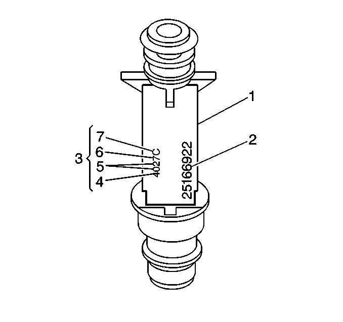
The eight digit part number
(2) is identified on the fuel injector body (1). A four digit build date (3)
is also located on the fuel injector body. the first digit (4) indicates
the month in which the fuel injector was built. For example, 1=January, 2=February,
....9=September, O=October, N=November and D=December. The second and third
digit (5) indicates the day of the month. The fourth digit (6) indicates
the last digit of the year in which the fuel injector was built. Finally,
the fifth digit (7) indicates which plant shift built the fuel injector.
Fuel Pressure Regulator Assembly

The fuel pressure regulator
assembly is a diaphragm-operated relief valve with fuel pump pressure on one
side, and a regulator spring pressure and intake manifold vacuum on the
other side. The regulator's function is to maintain a constant pressure
differential across the injectors at all times. The pressure regulator
compensates for engine load by increasing the fuel pressure as the engine
vacuum drops. The fuel pressure regulator is serviced as a complete assembly.
With the ignition ON and engine OFF (zero vacuum), fuel pressure should
be 358-405 kPa (52-58 psi). Whenever the pressure is too
low, poor performance and a DTC P0171 could result. Whenever the pressure
is too high, excessive odor and a DTC P0172 could result.
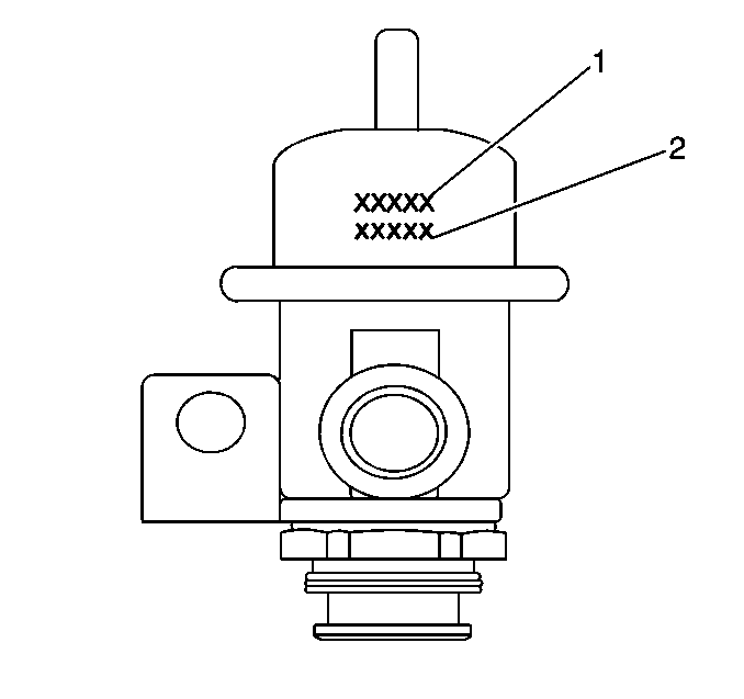
The last five digits of the part number (1) are identified on the fuel
pressure regulator. A five digit build date (2) is also located on the fuel
pressure regulator. The first three digits indicate the day of the year
in which the fuel pressure regulator was built. The fourth digit indicates
the year in which the fuel pressure regulator was built. Finally, the fifth
digit indicates which plant shift built the fuel pressure regulator.
Fuel Pump Electrical Circuit
When the ignition switch is turned to the ON position, the PCM energizes
the fuel pump relay for 2 seconds allowing the fuel pump to pressurize the
fuel system. If the PCM does not receive any ignition reference pulses,
engine cranking or running, within 2 seconds, the PCM de-energizes
the fuel pump relay, this causes the fuel pump to stop.
An inoperative fuel pump relay can result in long cranking times.
Idle Air Control (IAC) Valve Assembly

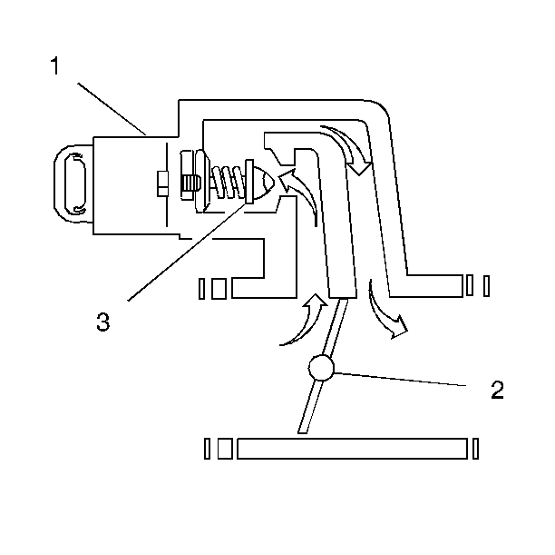
Engine idle speed is controlled by the powertrain control module (PCM)
through the IAC valve (1) mounted on the throttle body. The PCM sends voltage
pulses to the IAC valve motor windings causing the IAC valve pintle (3)
to move IN toward the seat, or OUT away from the seat, a given distance
(a step, or count), for each pulse. The commanded location, steps away from
the seated position, can be observed as a number of counts displayed on
a scan tool. The pintle movement controls the airflow around the throttle
valve (2), which in turn, controls engine idle speed: Pintle Extended=Decrease
RPM=Lower Counts. Pintle Retracted=Increase RPM=Higher Counts.
| • | The controlled or desired idle speed for all engine operating
conditions is programmed into the EEPROM of the PCM. The programmed engine
speeds are based on coolant temperature, park/neutral switch status, vehicle
speed, battery voltage, and A/C refrigerant pressure, if equipped. |
| • | The PCM learns the proper IAC valve positions to achieve warm,
stabilized idle speeds (RPM), desired for the various conditions (P/N or Drive,
A/C ON or OFF, if equipped). This information is stored in PCM keep alive
memories (information is retained after ignition is OFF). All other IAC
valve positioning is calculated based on these memory values. As a result,
engine variations due to wear, and variations in minimum throttle valve
position (within limits) do not affect engine idle speeds. This system provides
correct idle control under all conditions. This also means that disconnecting
power to the PCM can result in incorrect idle control or the necessity to
partially depress the accelerator when starting, until the PCM relearns
idle control. |
| • | Engine idle speed is a function of total airflow into the engine
based on IAC valve pintle position plus throttle valve opening plus calibrated
vacuum loss through accessories. |
| • | The minimum throttle valve position is set at the factory with
a stop screw. This setting allows enough air flow by the closed throttle valve
to cause the IAC valve pintle to be positioned a calibrated number of steps
(counts) from the seat during controlled idle operation. The minimum throttle
valve position for this engine is not the same as the minimum idle speed
associated with other fuel injected engines. The throttle stop screw is
filled at the factory following an adjustment. |
| | Important: Do Not try to remove the filler and readjust the stop screw. Misadjustment
may set a DTC P0506 or a DTC P0507.
|
| • | The PCM normally resets the IAC valve pintle position once during
each ignition cycle when vehicle speed increases above 20 mph on moderate
acceleration. During the reset, the PCM commands the IAC valve pintle to
retract completely, then move IN to the seated position (to establish the
zero count position), and then back out to the desired position. The IAC
is relearned only once per ignition cycle. |
| • | The IAC valve also can be reset without driving the vehicle by
using this service procedure: |
| 1. | Turn ON ignition, with the engine OFF. |
| 2. | Turn ignition OFF for ten seconds. |
| 3. | Start engine and check for proper idle operation. |
| • | Whenever the IAC valve is disconnected and reconnected while the
engine is running, the resulting IAC valve counts may not correspond with
the actual IAC valve pintle position. When servicing the IAC valve, do not
disconnect or connect the valve until after the ignition has been OFF for
at least 10 seconds. This allows time for the PCM to move the IAC valve
to the 150 count position where the valve is parked while the ignition is
OFF. Whenever this procedure is not followed, the PCM will lose track of
IAC valve position resulting in starting or idle control problems until
the IAC valve is reset and pintle position is relearned. |
| • | IAC system problems may cause improper idle speeds, resulting
in a DTC P0506 or a DTC P0507. The DTC P0506 or the DTC P0507 tables should
be used to diagnose these problems. |
Throttle Position (TP) Sensor
The nonadjustable, throttle shaft-driven TP sensor is mounted on the
throttle body assembly opposite the throttle cam lever. The TP sensor
senses the throttle valve angle and relays the information to the Powertrain
Control Module (PCM). Knowledge of throttle angle is needed by the
PCM to properly control the injector control signals, pulses.


