Fuel Feed and Return Pipes And Hoses
The fuel feed and return hoses/pipes carry fuel from the fuel tank to the fuel rail assembly and back to the fuel tank.
Fuel Filler Cap
Notice: If a fuel tank filler pipe cap requires replacement, use only a fuel tank filler pipe cap with the same features. Failure to use the correct fuel tank filler pipe cap can result in a serious malfunction of the fuel system.
The fuel tank filler neck is equipped with a quarter-turn type fuel filler cap. A built in ratchet type torque limiting device prevents over tightening. In order to install, turn the fuel filler cap clockwise until a clicking noise is heard. This signals that the correct torque has been reached and the fuel filler cap is fully seated. A fuel filler cap that is not fully seated, may cause a malfunction in the emission system.
Fuel Level Sensor
The fuel sensor is attached to the modular fuel sender. The resistance of the fuel sensor changes with the fuel level by means of a rheostat. As the position of the float varies with the fuel level, the rheostat produces a variable resistance. The fuel gauge converts this variable resistance into the fuel level reading displayed on the instrument panel.
Fuel Pipe O-Rings
Fuel feed and return pipe threaded connections at the fuel rail and fuel filter are sealed with replaceable O-ring seals. These O-rings seals are made of special material, and should only be serviced with the correct service part.
Fuel Pump

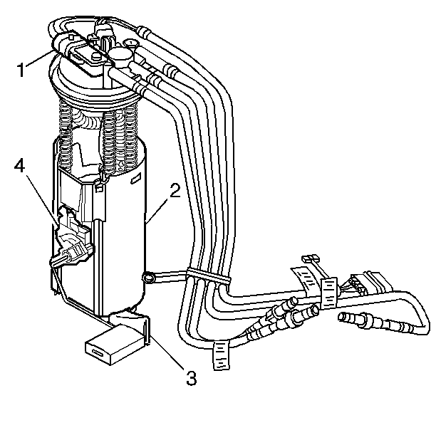
An electric fuel pump (2) located in the modular sender assembly is used to provide fuel pressure. To control fuel pump operation a fuel pump relay is used. When the ignition lock cylinder is turned to RUN position, the fuel pump relay activates the electric fuel pump for approximately two seconds to prime the injectors. If the PCM does not receive reference pulses after this time, the PCM opens the fuel pump relay power circuit. The relay will reactivate the fuel pump when the PCM receives reference pulses.
Fuel Pump Strainer
A woven plastic strainer is located on the lower end of the fuel sender. This strainer prevents dirt from entering the fuel sender and also stops water unless the strainer becomes completely submerged in water. This strainer is self cleaning and normally requires no maintenance. Fuel stoppage at this point indicates that the fuel tank contains an abnormal amount of sediment or water. Therefore, should this occur, the fuel tank should be removed and thoroughly cleaned and the strainer replaced.
Fuel Tank
The fuel storage tank is made of plastic. It is held in place by two metal straps attached to the under body of the vehicle.
Fuel Tank Filler Neck
To help prevent refueling with leaded fuel, the fuel filler neck has a built in restrictor and deflector. The opening in the restrictor will accept only the smaller unleaded gasoline fuel nozzle which must be fully inserted to bypass the deflector.
Fuel Tank Pressure Sensor

The fuel tank pressure sensor (1) is mounted on top of the modular fuel sender. The sensor measures the difference between the fuel vapor pressure, or vacuum, in the fuel tank and the outside air pressure. A three wire electrical harness connects it to the Powertrain Control Module (PCM). The PCM supplies a 5 volt reference signal and ground to the sensor. The sensor will return a voltage between 0.1 volts and 4.9 volts back to the PCM depending on the fuel vapor pressure in the fuel tank. When the fuel pressure in the fuel tank is equal to the outside air pressure, such as when the fuel cap is removed, the output voltage will be 1.3 volts to 1.7 volts.
Fuel Vapor Pipe and Hoses
The fuel vapor line is made up of nylon line, steel pipe, and quick connectors. The vapor pipe, line, and hoses carry fuel vapors from the fuel tank to the charcoal canister. The fuel vapor line has a evaporative system service port located between the purge solenoid and the charcoal canister. The evaporative system service port is identified by a green colored cap The evaporative system service port allows connection for special tools in diagnosing the evaporative emissions system. The vapor lines extend from the fuel sender to the canister. However, it does not follow the same route as the fuel feed pipe. Under no conditions use copper or aluminum tubing to replace steel tubing. Those materials do not have satisfactory durability to withstand normal vehicle vibrations and corrosion.
In-Line Fuel Filter

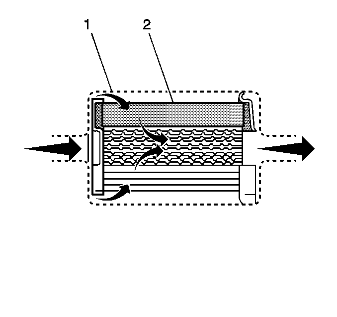
A stainless steel in-line fuel filter is used in the fuel feed line ahead of the fuel injection system. The steel filter housing (1) is constructed to withstand maximum fuel system pressure, exposure to fuel additives, and changes in temperature. The filter element (2) is made of paper, and is designed to trap particles in the fuel that may damage the injection system. A quick-connect type fitting is used at one end and an O-ring where the fuel pipe screws into the fuel filter body on the other end.
Modular Fuel Sender Assembly

The modular fuel sender assembly mounts in the top of the fuel tank and is spring loaded to the bottom. It is designed to:
| • | Provide optimum fuel level in the internal fuel reservoir during all fuel tank levels and driving conditions. |
| • | Improve the measuring accuracy of the fuel tank level. |
| • | Filters coarse contaminates from the fuel. |
| • | House the fuel pump and helps prevent fuel pump noise. |
| • | Include a check valve to inhibit back flow of fuel from the fuel system. |
The fuel sender consists of the following serviceable components:
| • | Fuel strainer (3) |
| • | Level sensor (4) |
| • | Fuel tank pressure sensor (1) |
| • | Fuel sender O-ring |
Nylon Fuel Pipes
Caution: In order to Reduce the Risk of Fire and Personal Injury:
• If nylon fuel pipes are nicked, scratched or damaged during installation,
Do Not attempt to repair the sections of the nylon fuel pipes. Replace them. • When installing new fuel pipes, Do Not hammer directly on the
fuel harness body clips as it may damage the nylon pipes resulting in a possible
fuel leak. • Always cover nylon vapor pipes with a wet towel before using a
torch near them. Also, never expose the vehicle to temperatures higher than
115°C (239°F) for more than one hour, or more than 90°C (194°F)
for any extended period. • Before connecting fuel pipe fittings, always apply a few drops
of clean engine oil to the male pipe ends. This will ensure proper reconnection
and prevent a possible fuel leak. (During normal operation, the O-rings located
in the female connector will swell and may prevent proper reconnection if
not lubricated.)
Nylon fuel pipes are designed to perform the same job as the steel or rubber fuel lines that they replace. The nylon pipes are constructed to withstand the maximum fuel system pressure, exposure to fuel additives and changes in temperature. There are two sizes used: 3/8 inch ID for the fuel feed, and 5/16 inch ID for the fuel return and are used on the modular sender. The nylon fuel pipes are somewhat flexible and can be formed around gradual turns. However, if forced into sharp bends, the nylon pipes will kink and restrict the fuel flow. Also, once exposed to fuel, the nylon pipes may become stiffer and are more likely to kink if bent too far. Take special care when working on a vehicle with nylon pipes.
On-Board Refueling Vapor Recovery System (ORVR)

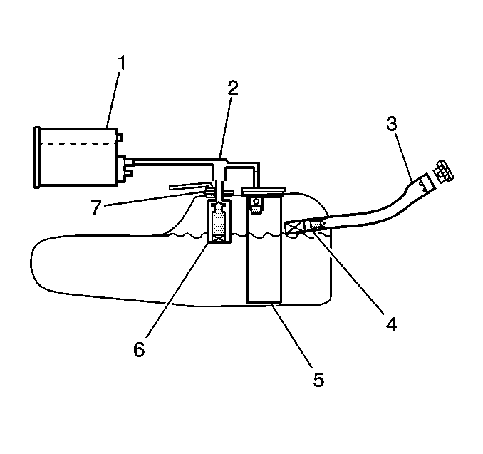
The on-board refueling vapor recovery system (ORVR) is an onboard vehicle system designed to recover fuel vapors during the vehicle refueling operation. The flow of liquid fuel down the filler neck provides a liquid seal which prevents vapor from leaving the fuel system by transporting vapor to the EVAP canister for use by the engine. Listed below are the ORVR system components with a brief description of their operation:
| • | EVAP canister (1)-- the EVAP canister receives refueling vapor from the fuel system, stores the vapor and releases the vapor to the engine upon demand. |
| • | Vapor lines (2)-- transports fuel vapor from the tank assembly to the EVAP canister. |
| • | Fuel filler pipe (3)-- the pipe which carries fuel from the fuel nozzle to the fuel tank. |
| • | Check valve (4)-- the check valve limits fuel spitback from the fuel tank during the refueling operation by allowing fuel flow only into the fuel tank. This check valve is located at the bottom of the fuel filler pipe. |
| • | Modular fuel sender assembly (5)-- this assembly pumps fuel to the engine from the fuel tank. |
| • | Fill limiter vent valve (FLVV) (6)-- this valve acts as a shutoff valve located in the fuel tank and has the following functions: |
| • | Controls the fuel tank fill level by closing the primary vent from the fuel tank. |
| • | Prevents fuel from exiting the fuel tank via the vapor line to the canister. |
| • | Provides fuel-spillage protection in the event of a vehicle rollover by closing the vapor path from the tank to the EVAP canister. |
| • | Pressure/vacuum relief valve (Optional)(7)-- the pressure/vacuum relief valve provides venting of excessive fuel tank pressure and vacuum. The valve is located in the fuel filler neck on a plastic fuel tank and in the fill limiter vent valve (FLVV) on a steel fuel tank. |
Notice: Do not use fuels containing methanol in order to prevent damage and corrosion to the fuel system.
The fuel supply is stored in the fuel tank. An electric fuel pump, which is located in the fuel tank with the fuel level sensor sending unit, pumps fuel through an in-line fuel filter to the engine. The pump provides fuel at a pressure more than is needed by the injectors. The fuel pressure regulator keeps fuel available to the injectors at a regulated pressure. The unused fuel is returned to the fuel tank by a separate line.
Quick-Connect Fittings
Quick-connect fittings provide a simplified means of installing and connecting fuel system components. The fittings consist of a unique female connector and a compatible male pipe end on the fuel rail. O-rings, located inside the female connector, provide the fuel seal. Integral locking tabs or fingers hold the fittings together.
Fuel Vapor Pipe and Hoses
The fuel vapor line is made up of nylon line, steel pipe, and quick connectors. The vapor pipe, line, and hoses carry fuel vapors from the fuel tank to the charcoal canister. The fuel vapor line has a evaporative system service port located between the purge solenoid and the charcoal canister. The evaporative system service port is identified by a green colored cap The evaporative system service port allows connection for special tools in diagnosing the evaporative emissions system. The vapor lines extend from the fuel sender to the canister. However, it does not follow the same route as the fuel feed pipe. Under no conditions use copper or aluminum tubing to replace steel tubing. Those materials do not have satisfactory durability to withstand normal vehicle vibrations and corrosion.
