For 1990-2009 cars only
Fuel Level Sensor Replacement Steel Tank
Removal Procedure
- Relieve fuel system pressure. Refer to Fuel Pressure Relief .
- Drain the fuel tank. Refer to Fuel Tank Draining .
- Remove the fuel tank. Refer to Fuel Tank Replacement .
- Remove the modular fuel sender assembly. Refer to Fuel Sender Assembly Replacement .
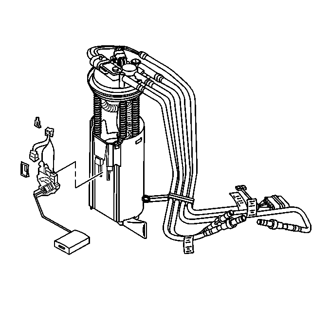
- Remove the fuel level sensor from the modular fuel sender.

Installation Procedure
- Install the fuel level sensor to modular fuel sender.
- Install the fuel sender assembly. Refer to Fuel Sender Assembly Replacement .
- Install the fuel tank. Refer to Fuel Tank Replacement .
- Refill the fuel tank.
- Connect the negative battery cable.
- Inspect for fuel leaks through the following steps:

| 6.1. | Turn the ignition switch to the ON position for two seconds |
| 6.2. | Turn the ignition switch to the OFF position for ten seconds. |
| 6.3. | Turn the ignition switch to the ON position |
| 6.4. | Check for fuel leaks. |
Fuel Level Sensor Replacement Plastic Tank
Removal Procedure
- Relieve the fuel system pressure. Refer to the Fuel Pressure Relief .
- Drain the fuel tank. Refer to Fuel Tank Draining .
- Remove the fuel tank. Refer to Fuel Tank Replacement .
- Remove the fuel sender assembly. Refer to Fuel Sender Assembly Replacement .
- Remove the fuel pump and fuel level sender electrical retaining clip at the top of the modular fuel sender assembly.
- Disconnect the fuel pump and fuel level sender electrical connector.
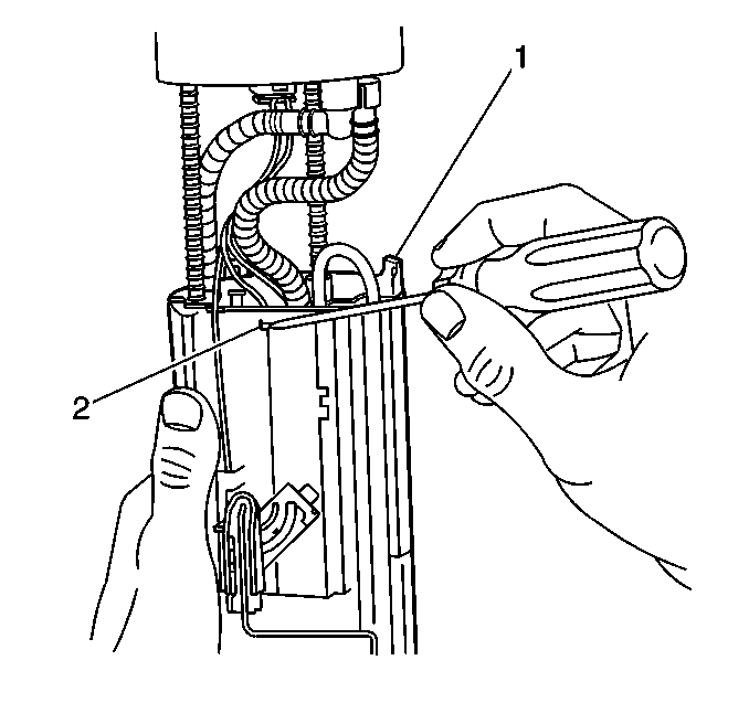
- Depress the 3 tabs (2) securing upper fuel reservoir to the lower reservoir (1).
- Depress the tab (1) and remove the upper reservoir from the lower reservoir.
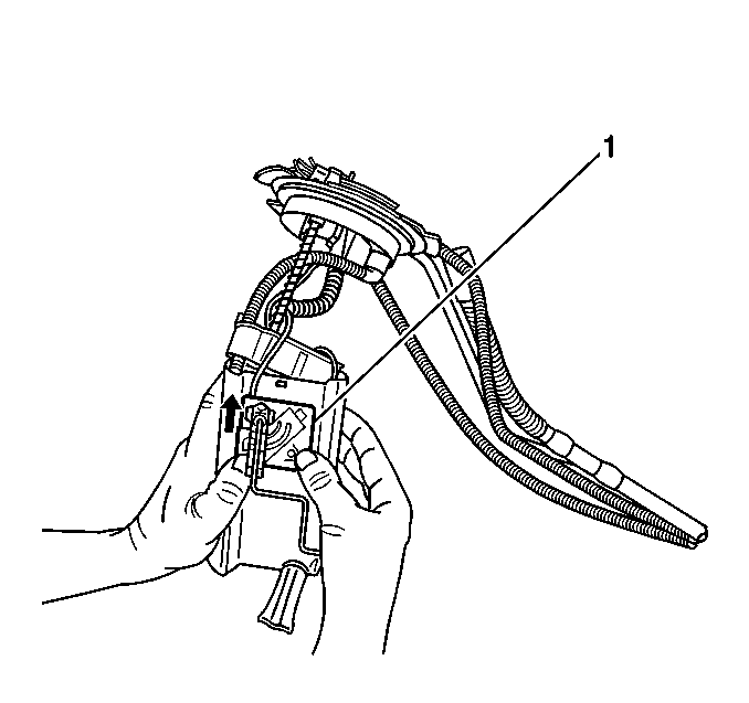
- Depress the tab (1) on the fuel level sensor (2).
- Push the fuel level sensor (1) up and out of the housing.
- Remove the retaining clip from the electrical connector.
- Remove the fuel level sender wires from the connector, taking care to note the location of the wires.


Installation Procedure
- Install the fuel level sensor (1) by sliding it down in the housing.
- Slide the upper reservoir into the lower reservoir (1) making sure the 3 tabs (2) lock in place.
- Connect the 2 wires into the connector and lock it with the retaining clip.
- Connect the fuel pump and fuel level sensor electrical connector and lock with it the retaining clip.
- Reinstall the fuel sender assembly. Refer to Fuel Sender Assembly Replacement .
- Reinstall the fuel tank. Refer to Fuel Tank Replacement .
- Refill the fuel tank.
- Reinstall the fuel fill cap.
- Connect the negative battery cable.
- Inspect for leaks using the following procedure:
Important:
• Make sure the wires are routed under the fuel level sender. • Make sure the tab locks in place.


Caution: Unless directed otherwise, the ignition and start switch must be in the OFF or LOCK position, and all electrical loads must be OFF before servicing any electrical component. Disconnect the negative battery cable to prevent an electrical spark should a tool or equipment come in contact with an exposed electrical terminal. Failure to follow these precautions may result in personal injury and/or damage to the vehicle or its components.
| 10.1. | Turn ON the ignition, with the engine OFF for 2 seconds. |
| 10.2. | Turn OFF the ignition for 10 seconds. |
| 10.3. | Turn ON the ignition, with the engine OFF. |
| 10.4. | Inspect for fuel leaks. |
