| Figure 1: |
Cell 10: Cooling Fan, BATT1, BATT2, IGN, and ABS Fuses

|
| Figure 2: |
Cell 10: RR DEFOG, PWR ACC and STOP/HAZ Fuses

|
| Figure 3: |
Cell 10: PCM, BLO, A/C and ABS Fuses

|
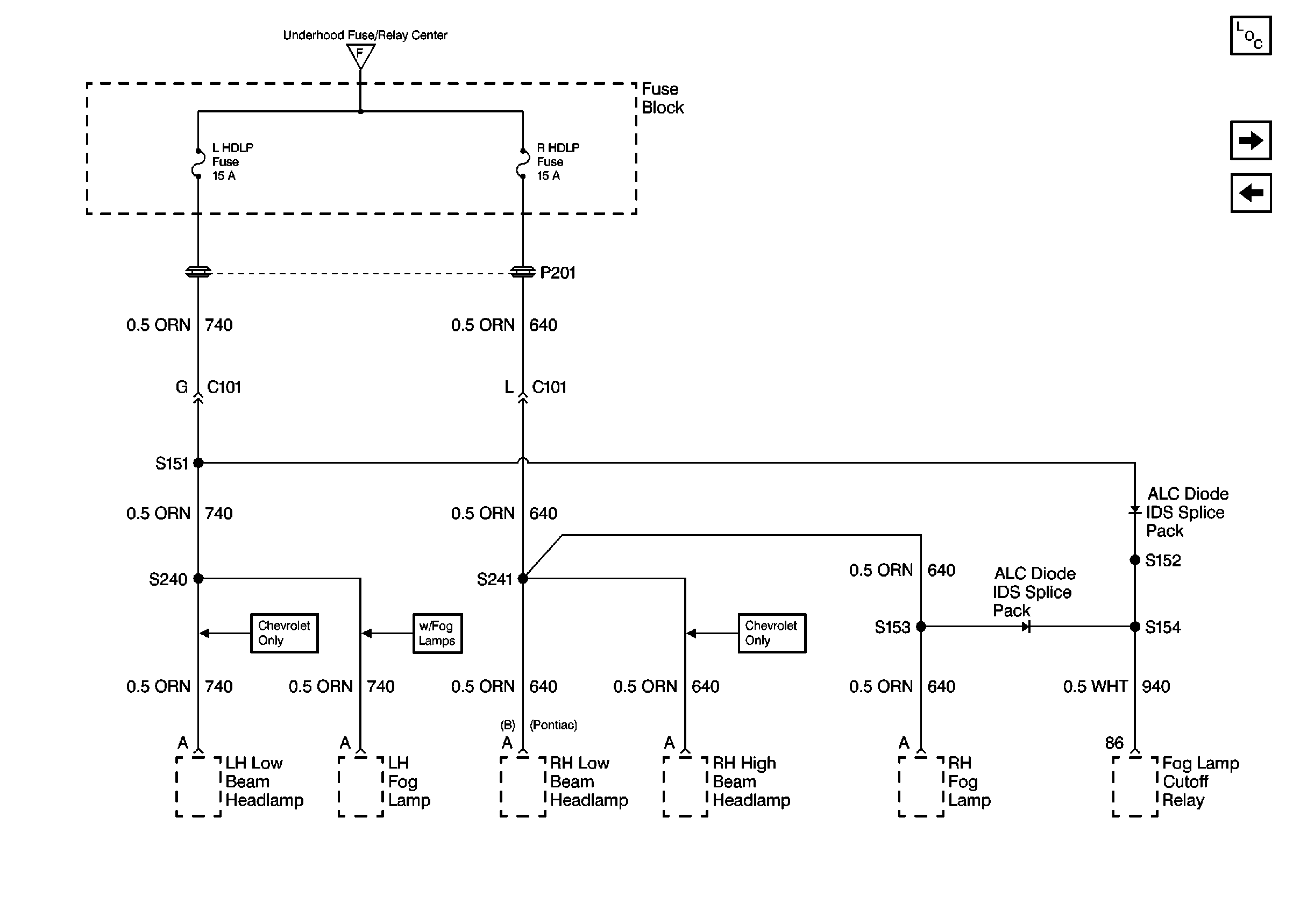
| Figure 4: |
Cell 10: L HDLP and R HDLP Fuses
|
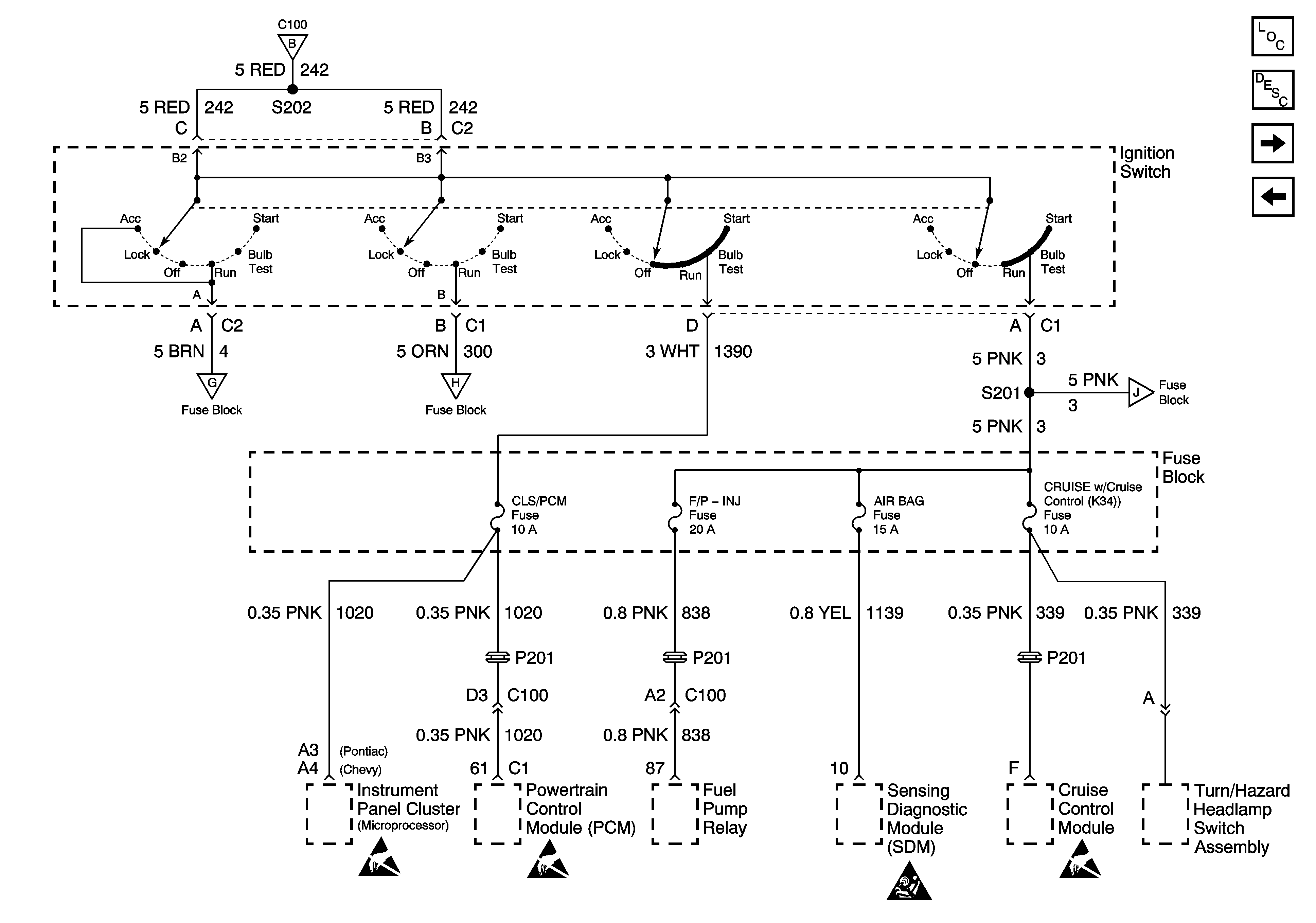
| Figure 5: |
Cell 10: CLS/PCM, F/P INJ, AIR BAG and CRUISE Fuses
|
| Figure 6: |
Cell 10: Wiper and Radio Fuses

|
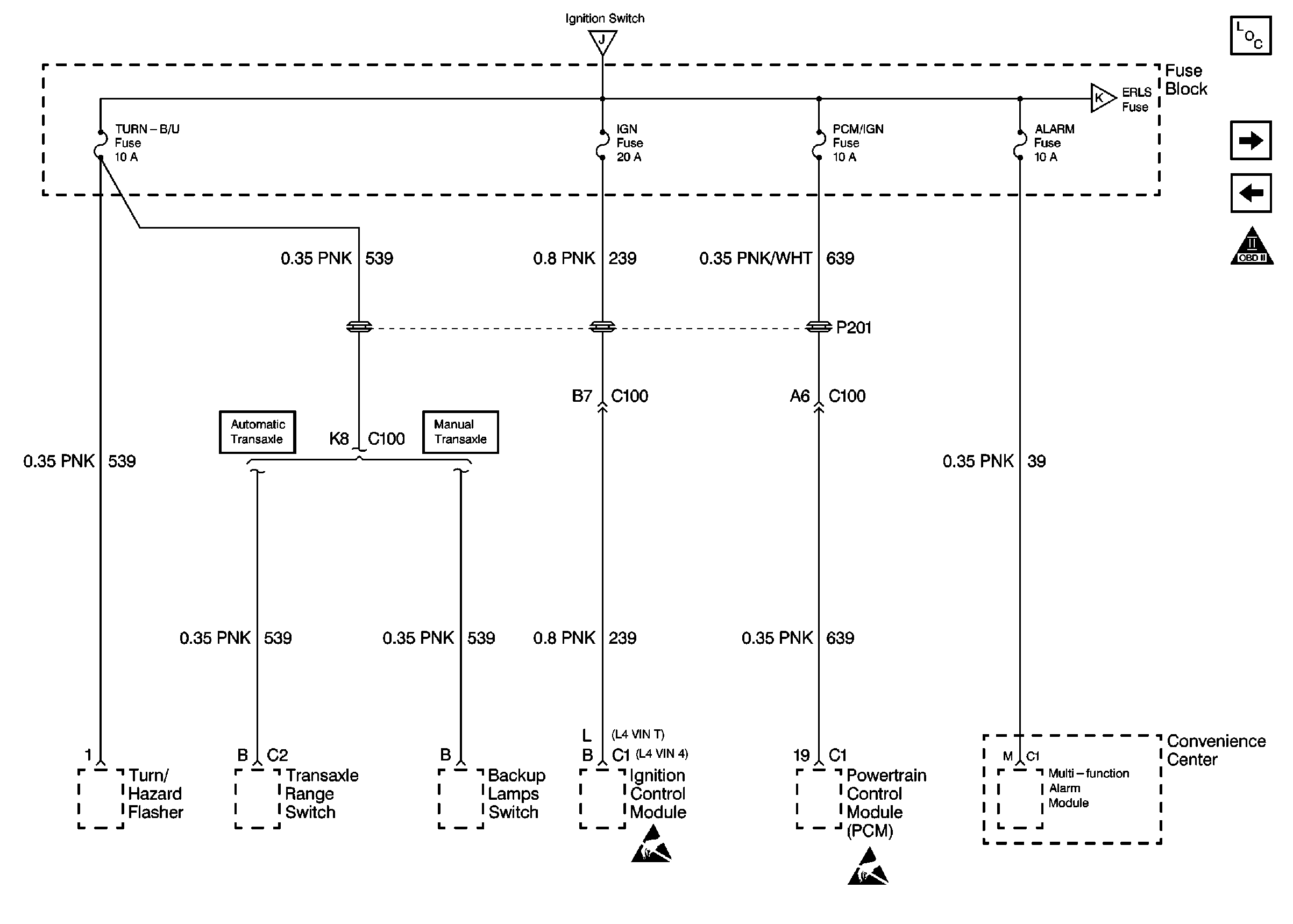
| Figure 7: |
Cell 10: Turn B/U, IGN, PCM/IGN and Alarm Fuses
|
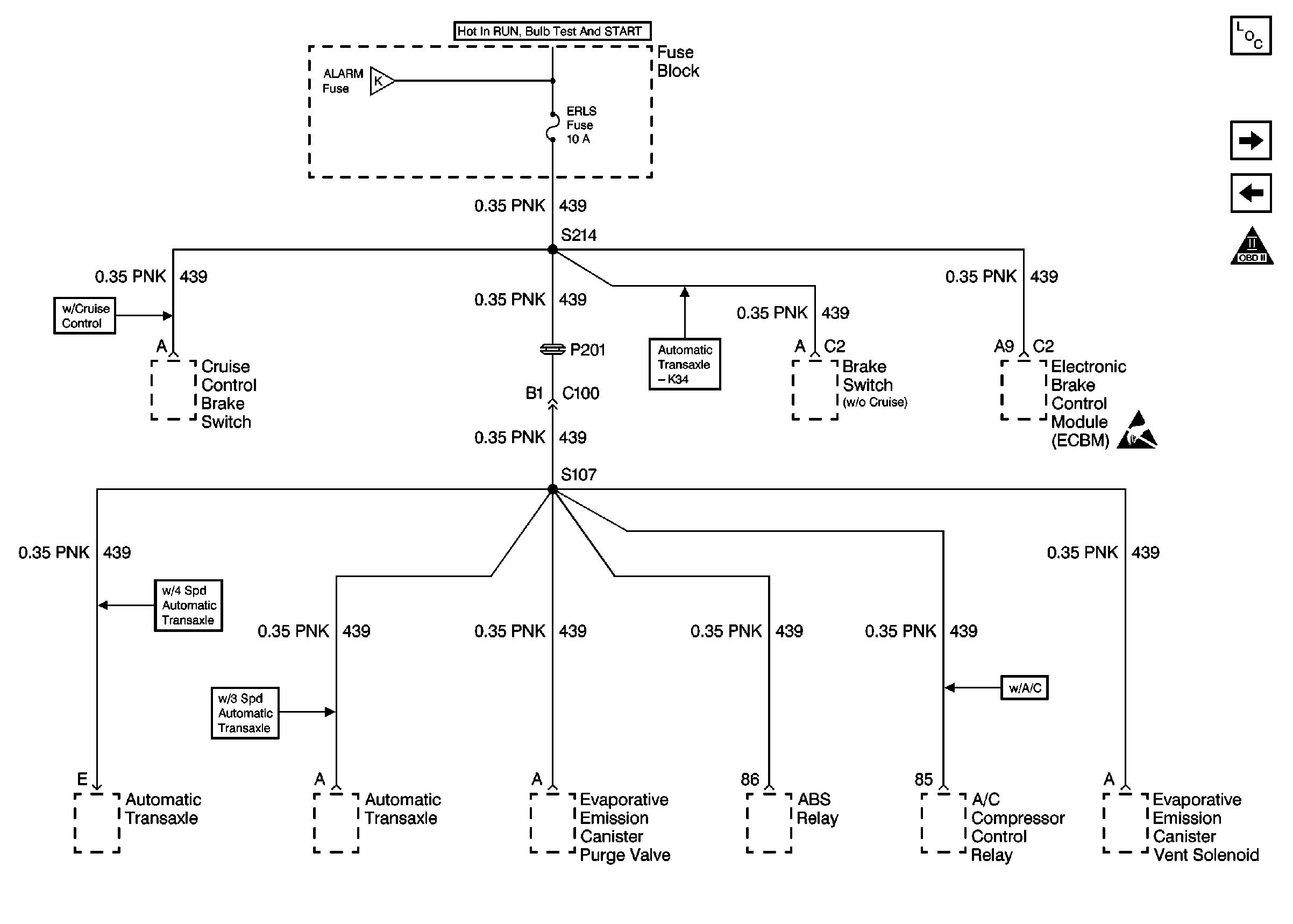
| Figure 8: |
Cell 10: ERLS Fuse
|
| Figure 9: |
Power Distribution Schematics (Cell 10: INST/LPS Fuse)

|
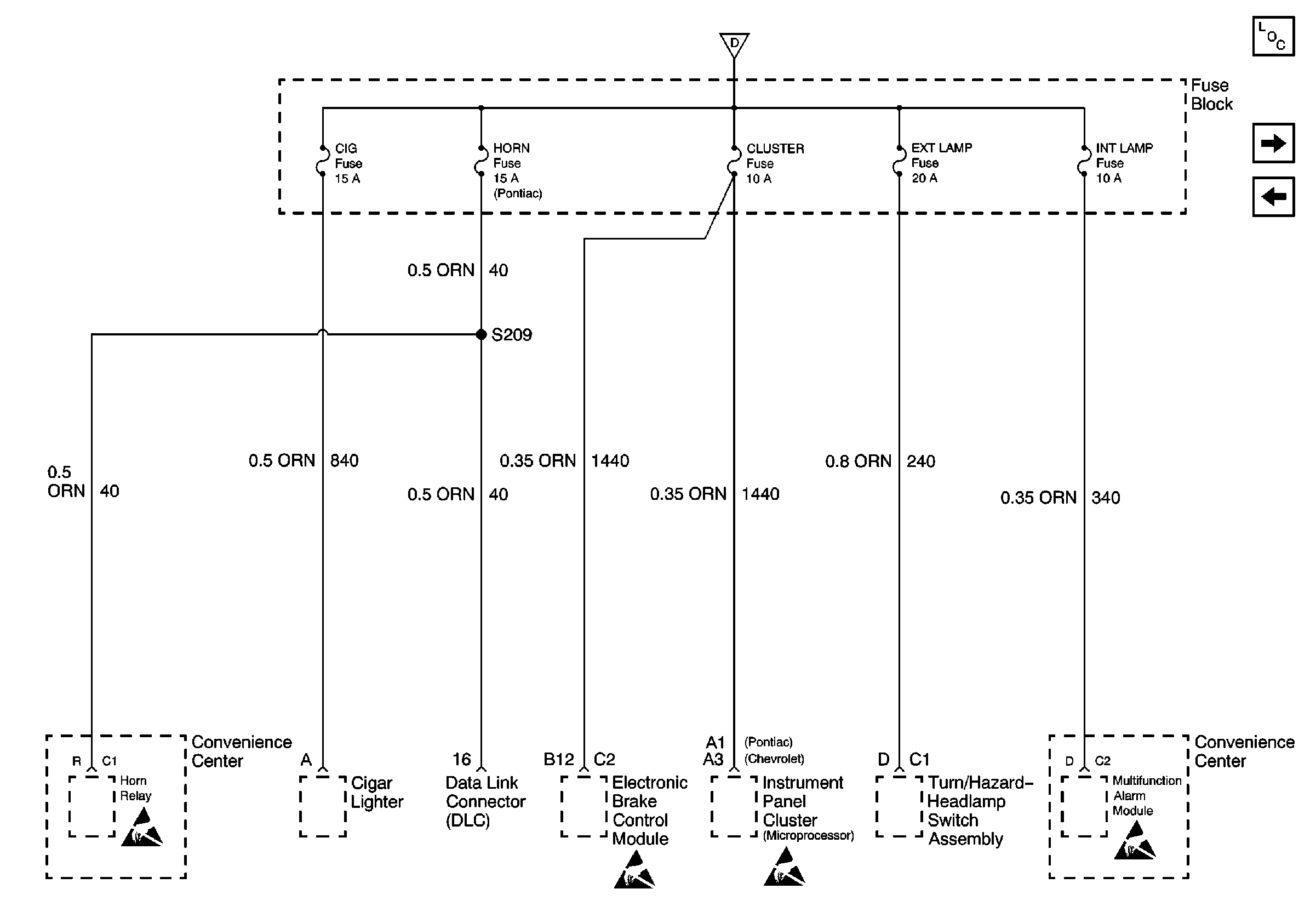
| Figure 10: |
Power Distribution Schematics (Cell 10: CIG, Horn, Cluster, EXT Lamp
and INT Lamp Fuses)
|
| Figure 11: |
Cell 10: HVAC, O2 HTR and PWR Window Fuses

|
