The basic function of the fuel metering system is to control fuel delivery to the engine. The fuel is delivered to the engine by individual fuel injectors mounted in the intake manifold near each cylinder.
The two most important inputs for fuel control are the Mass Air Flow (MAF) sensor and the Heated Oxygen Sensor 1 (HO2S 1).The MAF sensor provides the Powertrain Control Module (PCM) with engine air intake quantity, while the HO2S 1 provides the PCM with exhaust stream oxygen content information. The PCM modifies the air/fuel mixture by changing the injector pulse width signal sent to the injectors. By constantly measuring the air intake and the exhaust oxygen content and adjusting the injector pulse width, the air fuel ratio is kept very close to the optimal 14.7:1. This is the range at which the Three-Way Catalytic Converter (TWC) operates most effectively and at which the emissions of this vehicle are kept to a minimum. The constant tailoring of the air/fuel ratio is based upon feedback from the HO2S 1 and is referred to as Closed Loop operation.
Fuel Delivery System
The fuel in the fuel tank is pumped by the fuel pump, filtered by the fuel filter and fed under pressure to each injector through the fuel rail. The fuel pressure applied to the fuel injector (the fuel pressure in the fuel feed pipe) is always kept higher than the pressure in the intake manifold by the fuel pressure regulator. The fuel is injected into the intake port of the cylinder head when the injector opens according to the injection pulse signal from the Powertrain Control Module (PCM). The fuel relieved by the fuel pressure regulator returns through the fuel return pipe to the fuel tank.
Fuel Injection Operation
The Powertrain Control Module (PCM) controls the amount of fuel the fuel injector supplies to each cylinder by controlling the ON time (length of pulse) of each individual injector. The delivery timing of the fuel into the cylinder head intake port by the fuel injector is controlled by the PCM. The timing and pulse of the fuel injectors is carefully calculated with inputs from the various sensors, so that a suitable air/fuel mixture is supplied to the engine for every driving condition.
There are two types of injection timing. One is Synchronous Injection, in which the injection is synchronous with the ignition signal (or the signal from the Camshaft Position [CMP] sensor). The other is Asynchronous Injection, in which injection takes place independently of the ignition signal (or the signal from the Camshaft Position [CMP] sensor).
The Powertrain Control Module (PCM) first calculates the correct timing of the fuel injectors by factoring the engine speed and the air volume together. Then the PCM applies certain compensations that are based on the information provided by various sensors which detect the state of the engine and the current driving conditions.
Synchronous Injection
When starting the engine, the fuel injectors inject the fuel simultaneously and synchronously at every Camshaft Position (CMP) sensor signal. When the engine is starting at a cold state, the amount of fuel is determined by the Engine Coolant Temperature (ECT) sensor and is divided and injected.
Once the engine is running, the fuel injection occurs in a cylinder only when it is in the exhaust stroke. The Powertrain Control Module (PCM) detects the compression stroke of the No. 1 cylinder through the CMP sensor signal.
Asynchronous Injection
Whenever a change in the throttle valve opening exceeds a specified value (as determined by the PCM), additional fuel is injected simultaneously into the cylinders which are in the intake and exhaust strokes. This is in addition to the above synchronous injection and is not based on the ignition signal.
Engine Starting Enrichment
In order to improve starting performance, fuel enrichment during start up is carried out. For a certain time after the engine is started, the air/fuel mixture is enriched slightly in order to stabilize the engine speed. The amount of compensation varies depending on the engine coolant temperature as measured by the Engine Coolant Temperature (ECT) sensor.
Engine Warm-Up Enrichment
When the engine is cold, additional fuel is added in order to ensure good driveability. The level of enrichment of the air/fuel mixture is gradually decreased until the Engine Coolant Temperature (ECT) sensor reaches a specified value.
Acceleration Enrichment
During acceleration, the pulse of the fuel injectors is lengthened in order to deliver more fuel. The additional fuel required is relative to the engine coolant temperature. Acceleration Enrichment ensures smooth and reliable engine acceleration.
Power Enrichment
In order to provide maximum power during high engine load driving conditions, the air/fuel mixture is enriched when the throttle valve opening is greater than a specified (PCM determined) value.
System Voltage Compensation
A power supply system voltage drop will delay the mechanical operation of the fuel injector. The actual injector ON time becomes shorter when the system voltage decreases. In order to compensate for this, the fuel injector pulse width signal is lengthened.
Base Air/Fuel Ratio Compensation
The base air/fuel ratio may vary due to differences in individual engines and mileage. In order to compensate for such variations, feedback information is used to adjust the base air/fuel mixture to maintain the optimum air/fuel ratio.
Fuel Cutoff
Fuel injection stops when decelerating (i.e., when the throttle valve is at idle position and the engine speed is high), so that unburned gas will not be exhausted. Fuel injection starts again when the above conditions are no longer present.
Fuel delivery also stops when the engine speed exceeds 6,800 RPM. This will prevent engine overrun which adversely affects the engine. Fuel delivery starts again when the engine speed decreases to less than 6,500 RPM.
Air/Fuel Ratio Feedback Compensation (Closed Loop Operation)
In order to obtain efficient performance of the three-way catalytic converter (TWC) and a high clarification rate of CO, HC and NOx in the exhaust gas stream, the air/fuel mixture must be kept as close to the theoretical air/fuel ratio (14.7:1) as possible. In order to accomplish this the powertrain control module (PCM) first compares the input voltage from the heated oxygen sensor 1 (HO2S 1) with a specified reference voltage. If the HO2S 1 input voltage is higher than the specified reference voltage, the PCM determines that the air/fuel ratio is richer than the theoretical air/fuel ratio and reduces the fuel (lean command). If the input voltage from the HO2S 1 is lower than the specified reference voltage, the PCM determines that the air/fuel ratio is leaner and increases the fuel (rich command). By repeating these operations, the PCM can adjust the air/fuel ratio in order to be closer to the theoretical air/fuel ratio. Control of the fuel delivery system as just described is known as Closed Loop operation.
Air Fuel Mixture | Exhaust O2 Content | HO2S1 Output | Fuel System Response |
|---|---|---|---|
Lean Mixture | High Oxygen | Low Voltage | Rich Command |
Rich Mixture | Low Oxygen | High Voltage | Lean Command |
The Closed Loop fuel control operation will not take place under any of the following conditions:
| • | At engine start up. |
| • | When the fuel injection is increased just after engine start up. |
| • | When the engine coolant temperature (ECT) sensor is indicating a low coolant temperature. |
| • | When the engine is operating under a high demand, such as wide open throttle (WOT). |
| • | At fuel cutoff. |
| • | When the HO2S 1 is cold (Open Loop operation). |
Engine Idle Speed Control Operation
The engine idle speed is controlled by the Powertrain Control Module (PCM) through the Idle Air Control (IAC) valve which allows more or less air to bypass the throttle valve. There are several reasons for idle speed control:
- Maintain the engine idle speed at the specified RPM at all times. The engine idle speed can vary due to any of the following reasons:
- Improve the driveability of the engine during warm up.
- Compensate for the change in the air/fuel mixture ratio when decelerating (dash-pot effect).
| - | A change in atmospheric pressure. |
| - | A change in the engine's condition over time. |
| - | Other factors causing the idle speed to change. |
The IAC valve opens the bypass air passage when it is energized by the PCM and closes it when de-energized.
The PCM detects the engine condition by using inputs and signals from various sensors and switches. While repeating the ON and OFF cycle of the IAC valve at a certain rate (200 times a second), the PCM controls bypass air flow (IAC valve opening) by increasing and decreasing the ON time portion of the cycle.
When the vehicle is at a stop and the throttle valve is at the idle position with the engine running, the engine idle speed is kept at a specified value (Desired Idle Speed).
Throttle Body
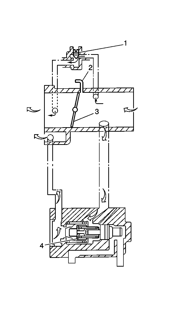
The throttle body consists of the main bore, the air bypass passage, the vacuum passage (2) (for Exhaust Gas Recirculation [EGR] system), and the following parts:
| • | A throttle valve (3) which is interlocked with the accelerator cable and controls the amount of intake air. |
| • | A fast idle air valve (4) which supplies the bypass air when the engine is cold. |
| • | An idle speed adjusting screw (2)which controls the amount of bypass air necessary to adjust idle air control duty (engine idle speed). |
| • | A Throttle Position (TP) sensor which detects the throttle valve opening and sends a signal to the PCM. |
Fuel Injector
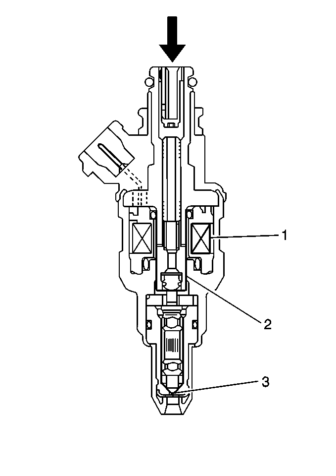
The fuel injector is an electromagnetic (solenoid) type injection nozzle which injects fuel into the intake port of the cylinder head according to the signals from the Powertrain Control Module (PCM). There are a total of four fuel injectors (one for each cylinder) located between the intake manifold and the fuel rail.
When the solenoid coil (1) of the fuel injector is energized by the PCM, it becomes an electromagnet and attracts the solenoid plunger (2). During this time, the needle valve (3), which is incorporated with the plunger, opens, and the fuel injector, which is under fuel pressure, injects the fuel. Because the stroke of the needle valve in the fuel injector is set constant, the amount of fuel injected at one time is determined by the length of time the solenoid coil is energized (pulse width injection time).
Fuel Pressure Regulator
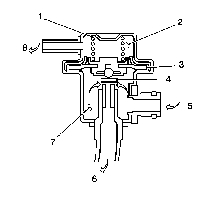
The fuel pressure regulator is a diaphragm-operated pressure relief valve consisting of a diaphragm (3) , a spring (1) and a valve (4). The fuel pressure regulator keeps the fuel pressure applied to the fuel injectors 290 kPa (41 psi) greater than the pressure in the intake manifold at all times.
The pressure applied (5) to chamber A (2) of the fuel pressure regulator is the intake manifold pressure (8) and the pressure applied to chamber B (7) is fuel pressure. When the fuel pressure rises more than 290 kPa (41 psi) higher than the intake manifold pressure, the fuel pushes the valve in the regulator open and excess fuel returns to the fuel tank via the return pipe (6).
Fuel Pulsation Damper
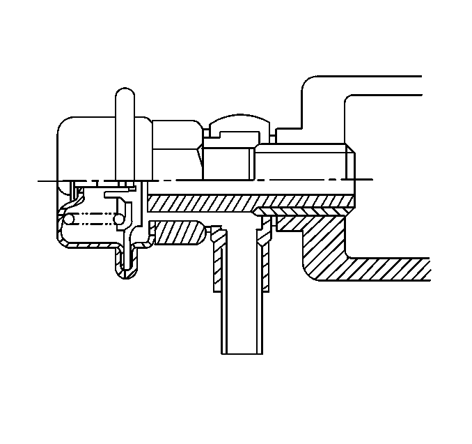
The fuel pulsation damper (1) is installed in the fuel rail. The fuel pressure applied to the fuel injectors is regulated by the fuel pressure regulator. When the fuel injectors inject fuel, a slight pulsation occurs in the fuel pressure. The purpose of the fuel pulsation damper is to remove these pulsations.
Fast Idle Air Valve
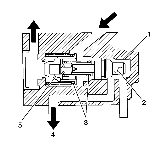
The fast idle air valve consists of a thermo-wax pellet (2), springs (4) and a valve (5) and is located in the throttle body (1). When the engine is cold (Engine Coolant Temperature [ECT] sensor is lower than 70°C [158°F]), the thermo-wax pellet contracts. In this state, the valve opens by the spring force, allowing the air to be drawn into the intake manifold (4). The amount of air drawn into the intake manifold will increase even though the throttle valve remains at the idle position The engine speed will rise to the fast idle state which is higher than the idle speed.
When the engine warms up, the thermo-wax pellet gradually expands, the piston pushes down the valve gradually, and the amount of air passing through the fast idle air valve decreases as does the engine speed. When the ECT reaches about 70°C (158°F), the valve is fully closed and the engine speed returns to the normal idle speed.
Idle Air Control (IAC) Valve
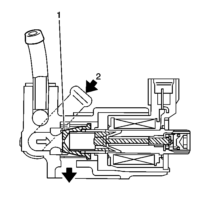
The Idle Air Control (IAC) valve (1) opens and closes the air bypass passage according to a signal from the Powertrain Control Module (PCM). When the IAC valve opens, air (2) is supplied to the intake manifold which increases the engine RPM for various engine loads.
