Special Tools
J 44394 Axle Seal Protector
Removal Procedure
- Remove the left rear wheel drive shaft. Refer to Wheel Drive Shaft Replacement.
- Remove the muffler and exhaust pipe. Refer to Exhaust Muffler Replacement.
- Remove the floor panel tunnel panel front closeout panel. Refer to Floor Panel Tunnel Panel Replacement - Front.
- Remove the floor panel tunnel rear panel. Refer to Floor Panel Tunnel Panel Replacement - Rear.
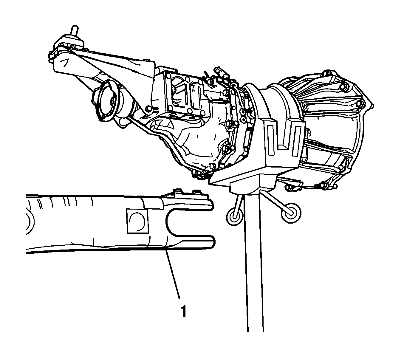
- Support the transmission with a suitable jack stand.
- Loosen, but DO NOT remove the driveline support to the transmission bolts (1).
- Remove the transmission close out panel. Refer to Transmission Support Replacement.
- Loosen, but DO NOT remove the left and right motor mount bolts.
- Remove the front propeller shaft bolts (1) and washer support tabs (2) from the transmission.
- Support the rear differential with a transmission jack stand.
- Remove the propeller shaft nuts and bolts from the rear differential.
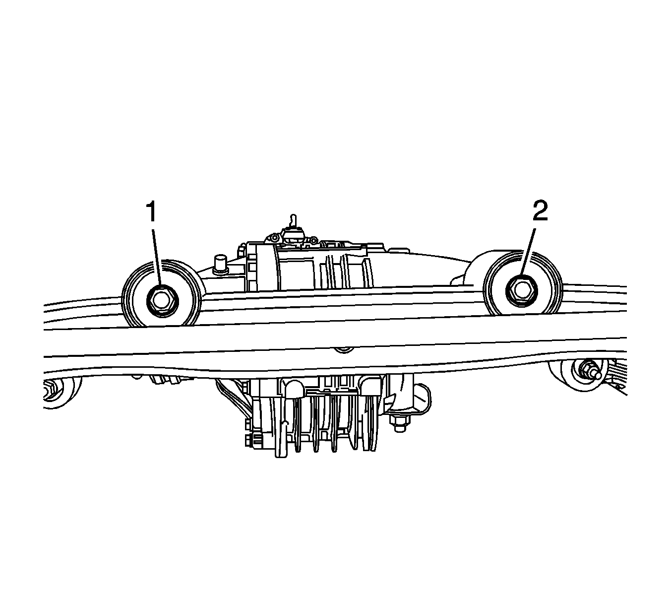
- Remove the left (1) and right (2) rear differential mount bolts.
- Lower the rear differential enough to clear the rear crossmember.
- Install the J 44394 protector and move the rear differential to the left side of the vehicle to remove the right rear wheel drive shaft.
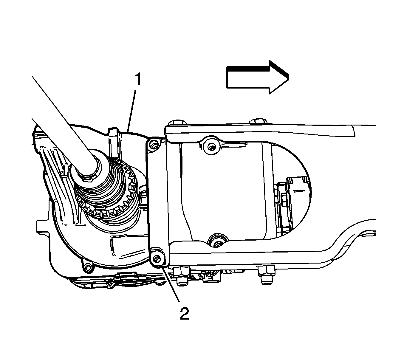
- Remove the four differential carrier bracket bolts (1).
- Separate the differential carrier (1) from the driveline support bracket (2).
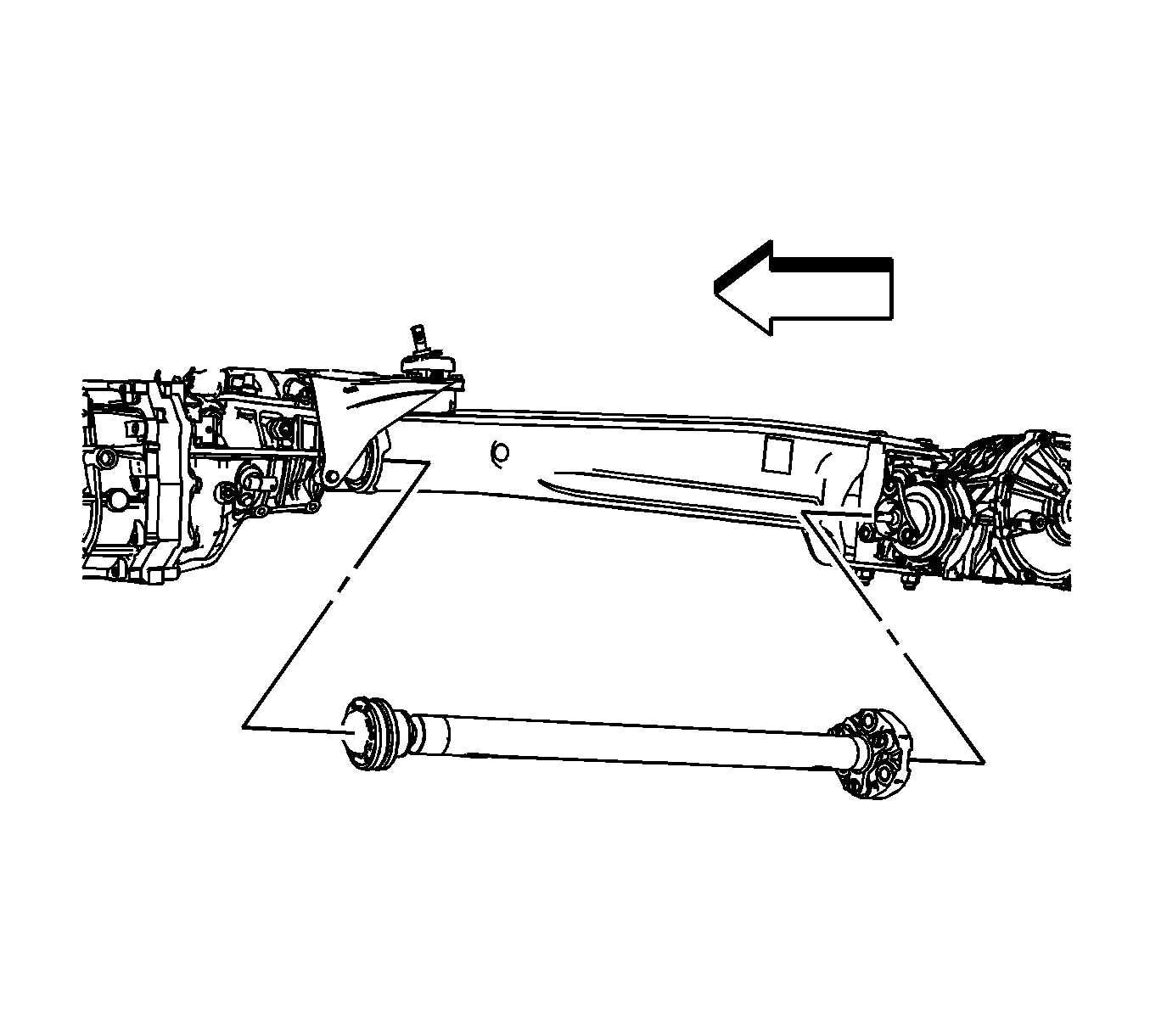
- Remove the propeller shaft from the vehicle.
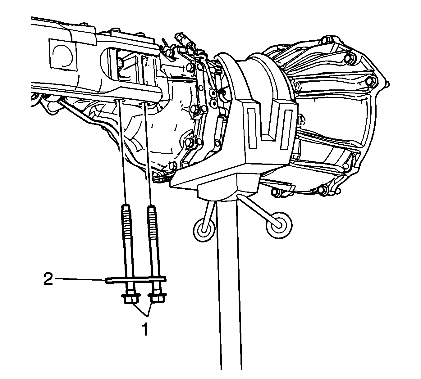
- Remove the driveline support bolts (1) and the washers (2) from the transmission.
- Remove the driveline support (1) from the transmission and the rear differential assembly.
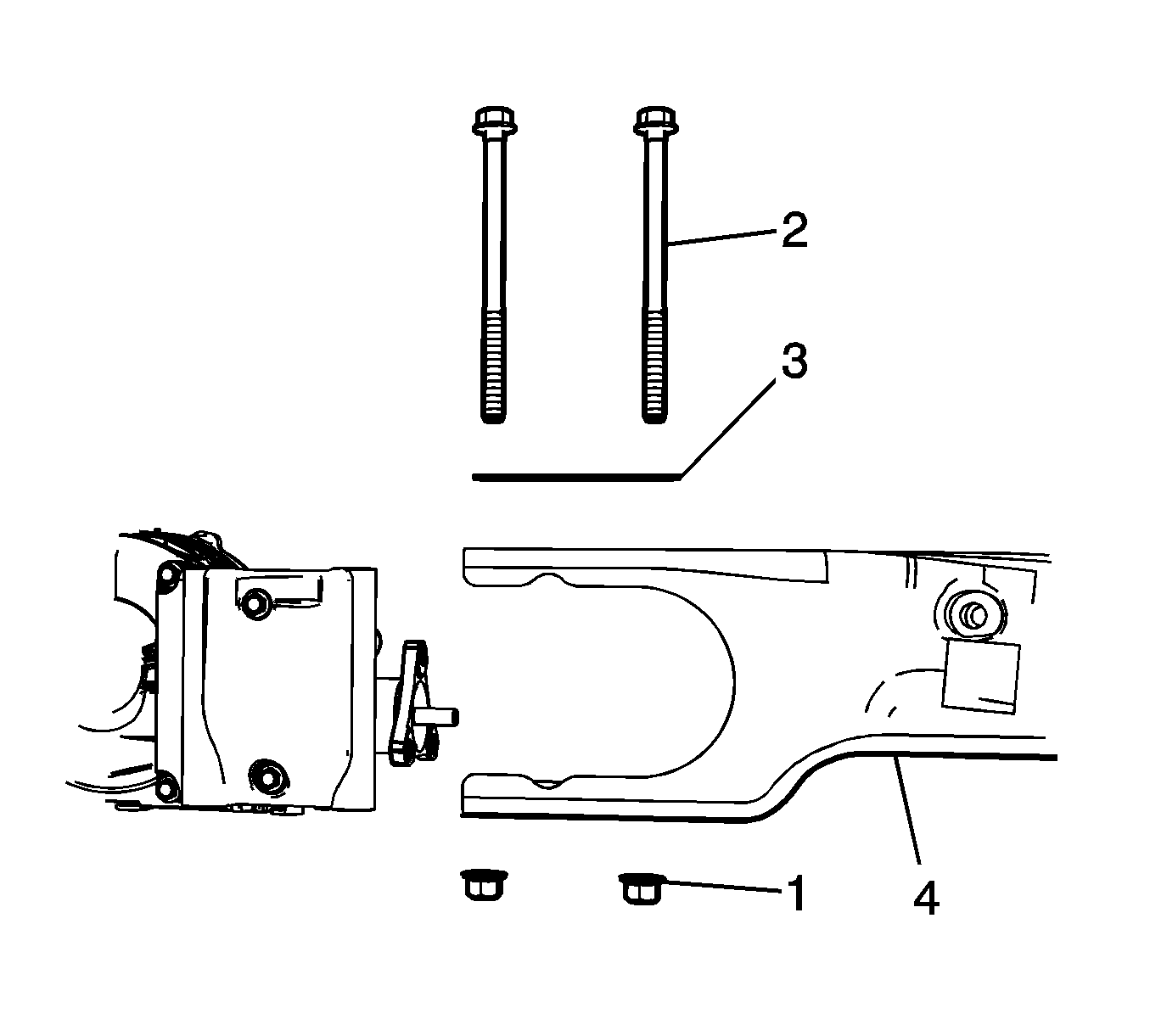
- If servicing the driveline support, remove the nut (1), bolt (2), and the washer block (3) from the driveline support.
- Remove the driveline support (4) from the rear differential assembly.
- If servicing the rear differential assembly, remove the rear differential assembly from the vehicle.

| • | For vehicles equipped with the 2.0L, refer to Engine Mount Replacement - Left Side and Engine Mount Replacement - Right Side. |
| • | For vehicles equipped with the 2.4L, refer to Engine Mount Replacement - Left Side and Engine Mount Replacement - Right Side. |


Note: The proper nuts and bolts to be removed are those where the nut is the closest or facing the rear differential drive flange. DO NOT remove the nuts and bolt where the nuts are facing the front or propeller shaft.

Note: DO NOT re-use the bolts, discard and use NEW only.
Note: Steps 18 and 19 are for the replacing the driveline support.

Note: Support the right rear wheel drive shaft with mechanics wire.
Installation Procedure
- Clean the bolt holes in the differential carrier with brake cleaner or other suitable solvents to remove any adhesive.
- If servicing the driveline support, position the driveline support (4) on the differential housing.
- Install the bolt plate (3), bolts (2) for the driveline support on the differential housing.
- Install the nuts (1) for the drive line support bolts (2) and tighten to 200 N·m (148 lb ft).
- Position the driveline support (1) on the transmission.
- Install the driveline support bolts (1) and washers (2).
- Raise the differential to just below the rear crossmember.
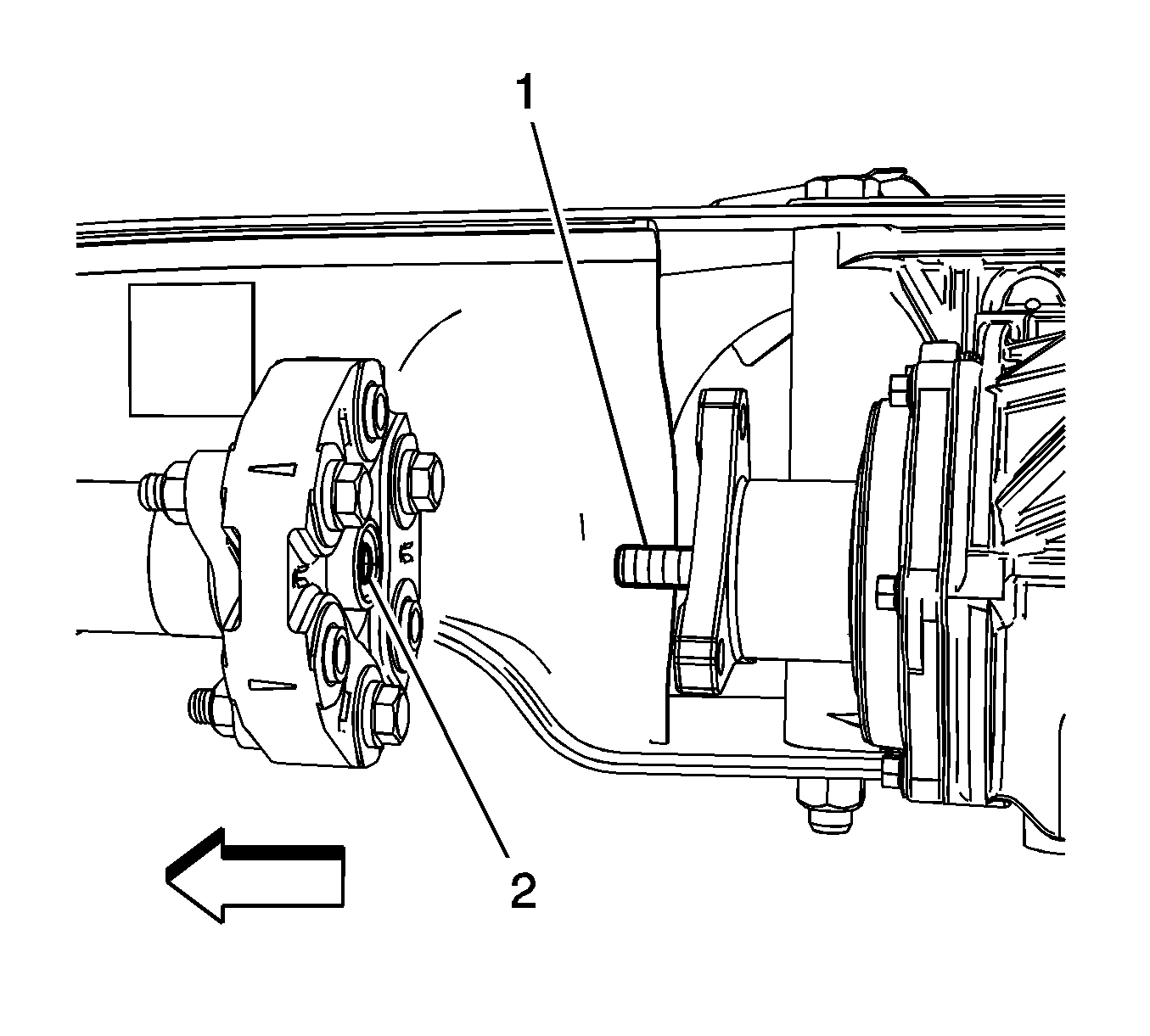
- Clean the pilot shaft (1) and the pilot hole (2) of any dirt or debris.
- Apply a small amount of chassis lube on the pilot shaft (1).
- Align the pilot shaft (1) and the pilot hole (2).
- Install the propeller shaft to the transmission and differential.
- Install the propeller shaft bolts (1) and washer support tabs (2) in the transmission drive flange.
- Align the differential carrier (1) and the torque beam bracket (2).
- Apply GM threadlocker to the NEW differential carrier bracket bolts (1). Refer to Adhesives, Fluids, Lubricants, and Sealers.
- Install the four new driveline support bracket bolts (1) and tighten to 80 N·m (59 lb ft).
- Raise and position the differential in the rear support.
- Install the left (1) and right (2) rear differential bolt and tighten to 175 N·m (129 lb ft).
- Tighten the rear propeller shaft bolts to 85 N·m (63 lb ft).
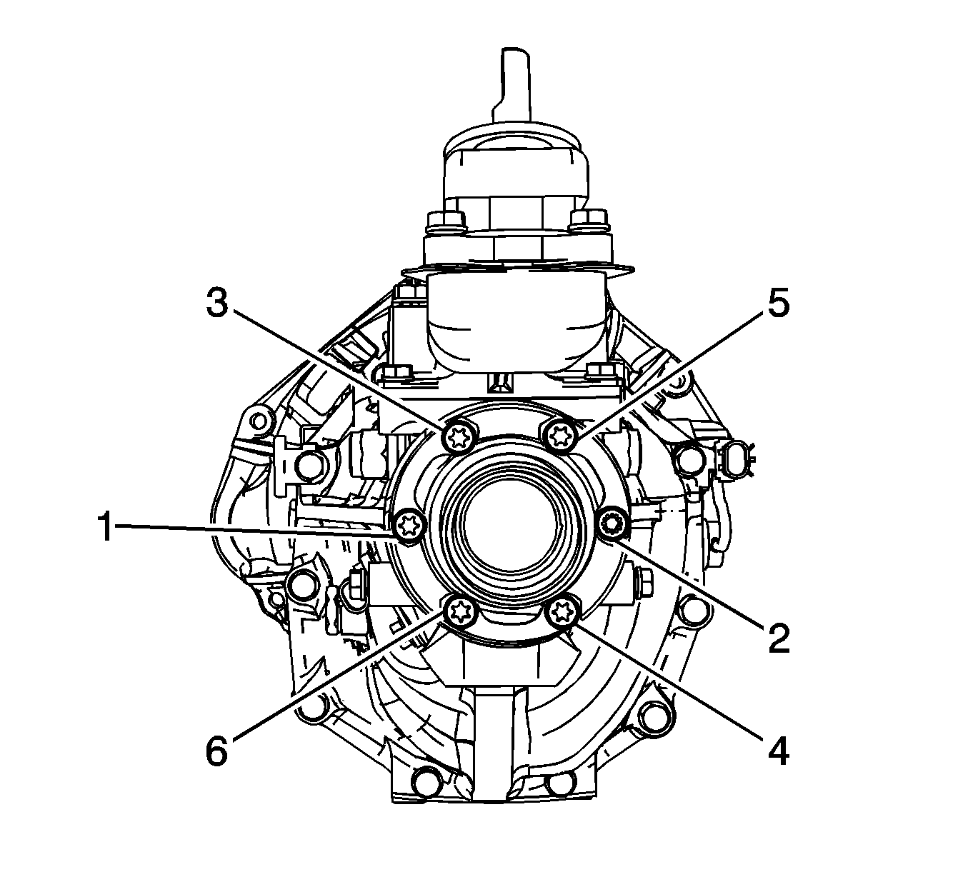
- Tighten the front propeller shaft bolts in sequence (1-6) to 40 N·m (30 lb ft).
- Install the left rear wheel drive shaft. Refer to Wheel Drive Shaft Replacement.
- Position a scale or known straight edge across the floor pan where the driveline tunnel closeout mounts to the body.
- Position another scale at the transmission output shaft oil seal slinger.
- Using the jack stand, raise or lower the transmission until a measurement of 80 mm (3.150 inch) is obtained.
- Tighten the driveline support bolts (1) at the transmission to 185 N·m (136 lb ft).
- Remove the jack stand from the rear differential.
- Tighten the left and right motor mount bolts.
- Remove the transmission jack stand.
- Install the transmission close out panel. Refer to Transmission Support Replacement.
- Install the floor panel tunnel panel front closeout panel. Refer to Floor Panel Tunnel Panel Replacement - Front.
- Install the floor panel tunnel rear panel. Refer to Floor Panel Tunnel Panel Replacement - Rear.
- Install the muffler and exhaust pipe from the vehicle. Refer to Exhaust Muffler Replacement.

Caution: Refer to Component Fastener Tightening Caution in the Preface section.


Note: Leave the driveline support bolts loose.



Note: In steps 11 and 12, finger tighten the front and rear propeller shaft nuts and bolts only. DO NOT torque the propeller shaft nuts and bolts until the differential and driveline support have been aligned and torqued to specifications.

Note: Ensure that the driveline support bracket and the differential are properly joined.

Note: Use only hands tools to tighten the driveline support bolts.

Note: Install the left and right rear differential bolts by hand before tightening to specifications.

Note: Failing to perform the following service procedure will create the wrong driveline angle for the propeller shaft and alignment of the transmission and the rear differential.

| • | For vehicles equipped with the 2.0L, refer to Engine Mount Replacement - Left Side and Engine Mount Replacement - Right Side. |
| • | For vehicles equipped with the 2.4L, refer to Engine Mount Replacement - Left Side and Engine Mount Replacement - Right Side. |

