GM Service Manual Online
For 1990-2009 cars only
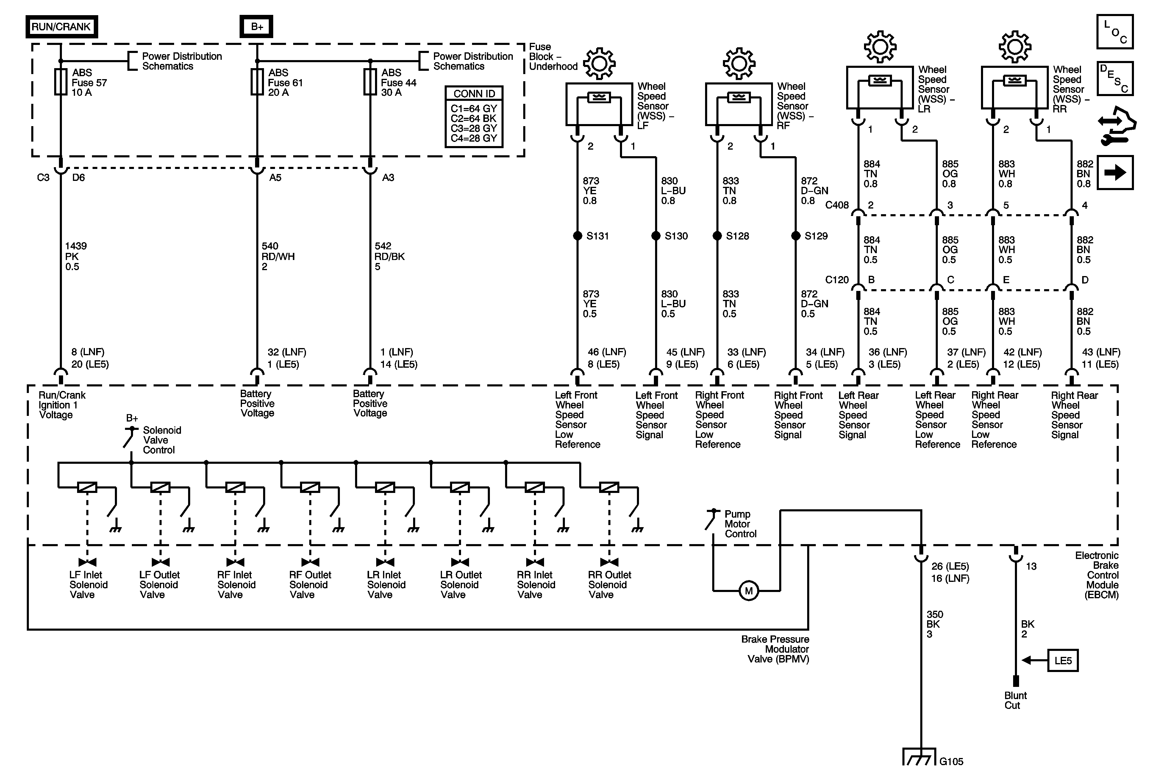
Figure 1:

Power, Ground and Wheel Speed Sensors


Object Number: 1829222  Size: FS
Master Electrical Component List
ABS Description and Operation
Control Module References
Brake Pedal Sensor, Indicator, and Traction Control Switch
B+ Bus Bar - 1 of 2
B+ Bus Bar - 2 of 2
G103, G304, G105, G104, and G106
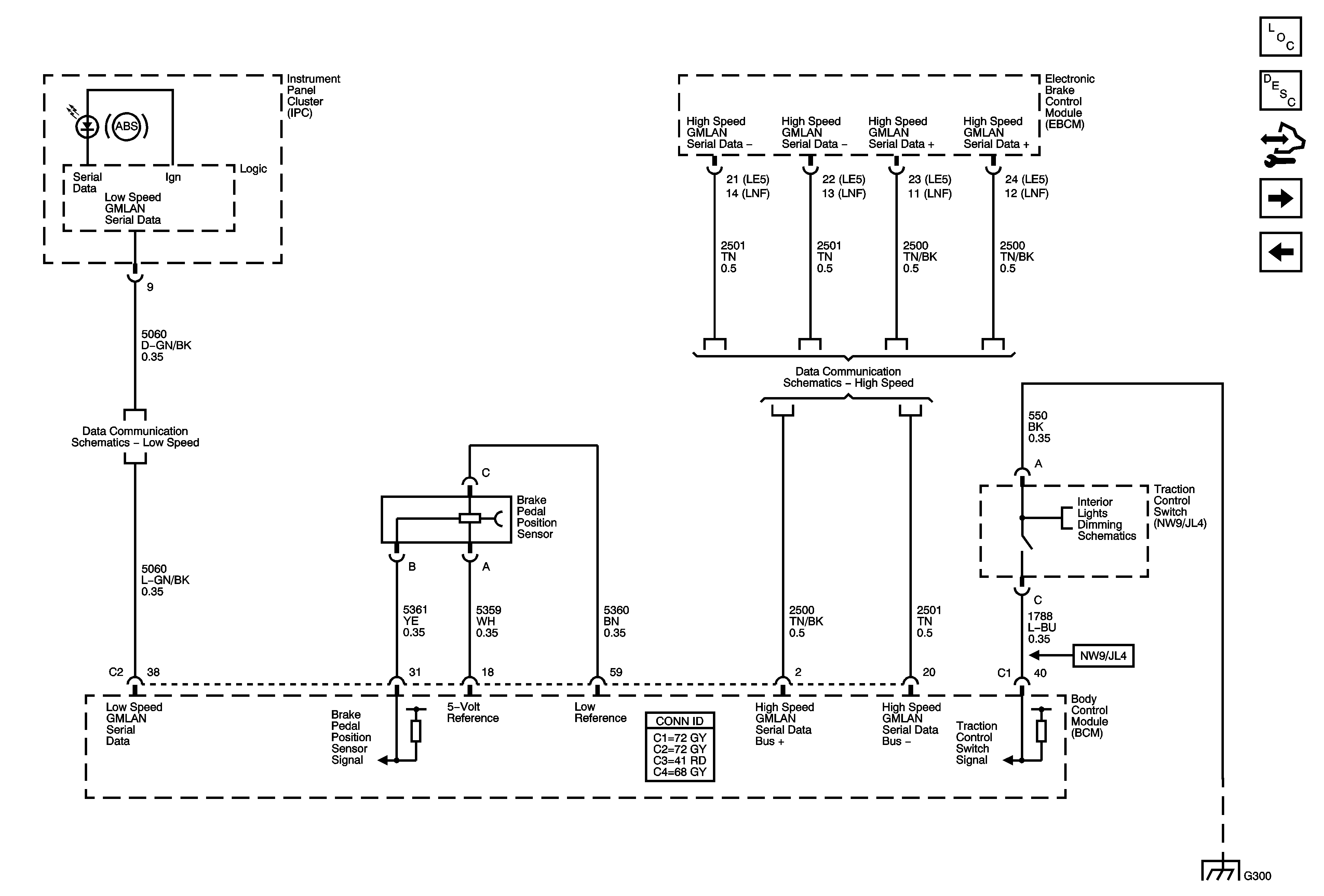
Figure 2:

Brake Pedal Sensor, Indicator, and Traction Control Switch


Object Number: 1829228  Size: FS
Master Electrical Component List
ABS Description and Operation
Control Module References
Stability Control Sensors (JL4)
Power, Ground, and Wheel Speed Sensors
Low Speed LAN
High Speed LAN
Lights
G300 - 2 of 2
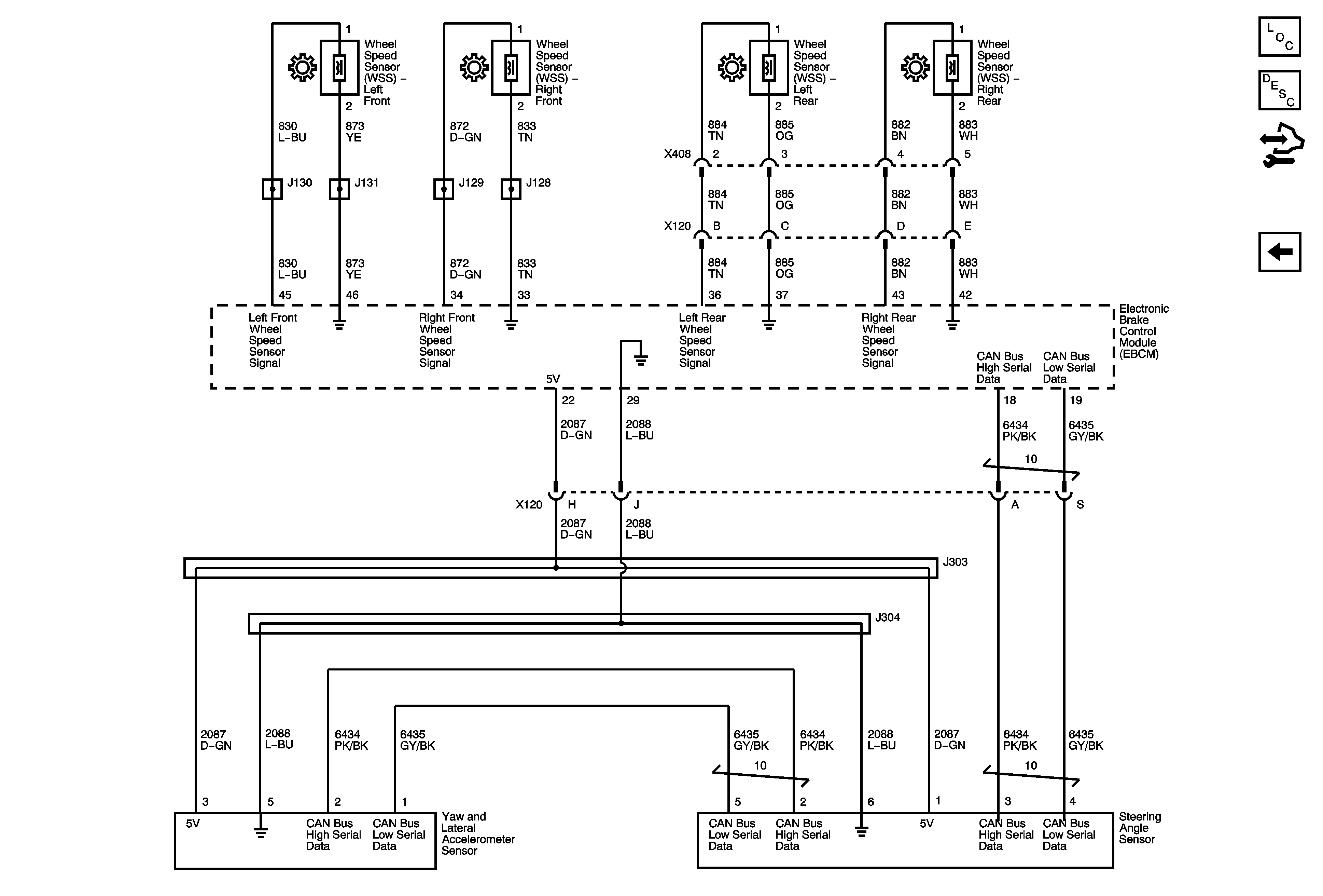
Figure 3:

Stability Control Sensors (JL4)


Object Number: 1844122  Size: FS
Master Electrical Component List
ABS Description and Operation
Control Module References
Brake Pedal Sensor, Indicator, and Traction Control Switch
Antilock Brake System Schematic Icons
Figure 1:

Power, Ground and Wheel Speed Sensors


Object Number: 1871227  Size: FS
Master Electrical Component List
ABS Description and Operation
Control Module References
Brake Pedal Sensor, Indicator, and Traction Control Switch
B+ Bus Bar - 1 of 2
B+ Bus Bar - 2 of 2
G103, G304, G105, G104, and G106
Figure 2:

Stability Control Sensors (JL4)


Object Number: 1871231  Size: FS
Master Electrical Component List
ABS Description and Operation
Control Module References
Brake Pedal Sensor, Indicator, and Traction Control Switch
Antilock Brake System Schematic Icons