C100 Engine Harness to the Transmission Harness (MN5)
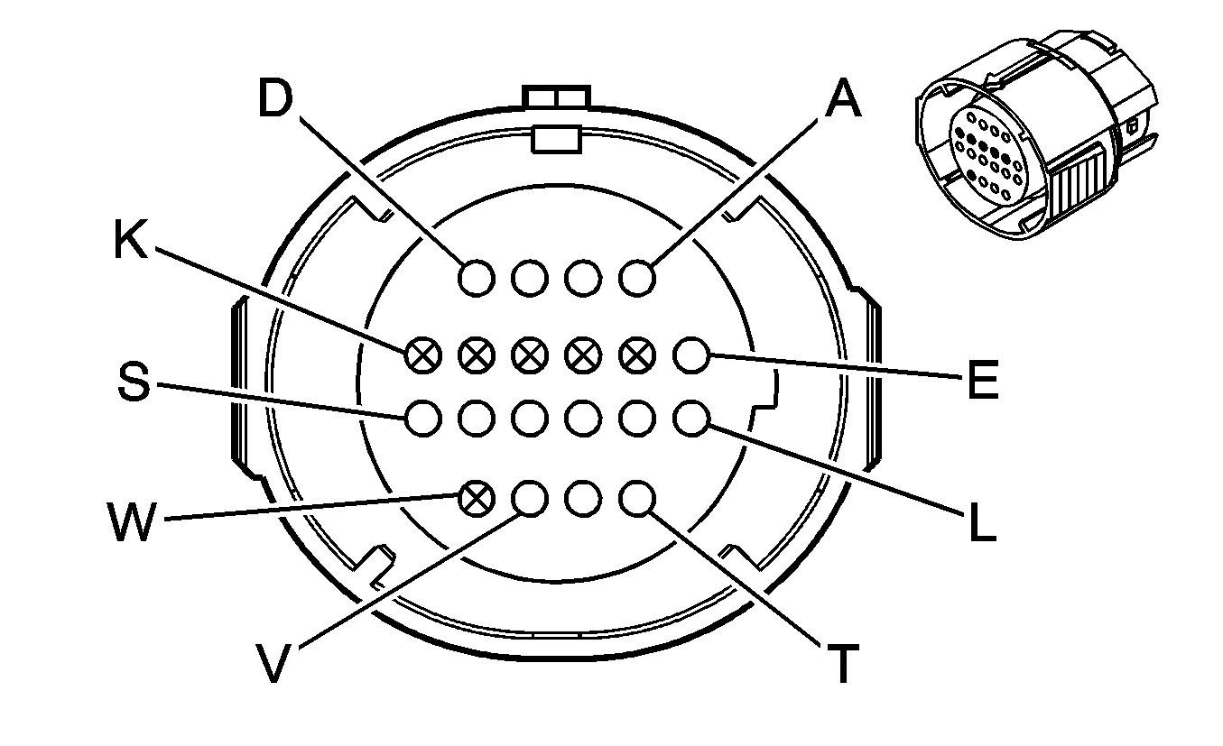
|
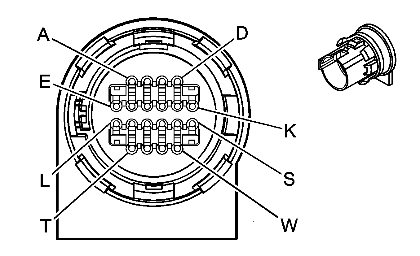
|
Connector Part Information
| Connector Part Information
|
Terminal Part Information
| Terminal Part Information
|
Pin | Wire Color | Circuit No. | Function | Pin | Wire Color | Circuit No. | Function |
|---|---|---|---|---|---|---|---|
A | L-GN | 1222 | 1-2 Shift Solenoid Valve Control | A | L-GN | 1222 | 1-2 Shift Solenoid Valve Control |
B | YE/BK | 1223 | 2-3 Shift Solenoid Valve Control | B | YE/BK | 1223 | 2-3 Shift Solenoid Valve Control |
C | OG/BK | 1228 | PC Solenoid Valve High Control (Sol. A) | C | OG/BK | 1228 | PC Solenoid Valve High Control (Sol. A) |
D | L-BU/WH | 1229 | PC Solenoid Valve Low Control (Sol. A) | D | L-BU/WH | 1229 | PC Solenoid Valve Low Control (Sol. A) |
E | PK | 1039 | Ignition 1 Voltage | E | PK | 1039 | Ignition 1 Voltage |
F-K | -- | -- | Not Used | F-K | -- | -- | Not Used |
L | YE/BK | 1227 | TFT Sensor Signal | L | YE/BK | 1227 | TFT Sensor Signal |
M | TN | 2762 | Low Reference | M | TN | 2762 | Low Reference |
N | -- | -- | Not Used | N | -- | -- | Not Used |
P | OG | 1226 | Transmission Fluid Pressure Switch Signal C | P | OG | 1226 | Transmission Fluid Pressure Switch Signal C |
R | D-BU | 1225 | Transmission Fluid Pressure Switch Signal B | R | D-BU | 1225 | Transmission Fluid Pressure Switch Signal B |
S | OG/BK | 1230 | AT ISS High Signal | S | OG/BK | 1230 | AT ISS High Signal |
T | TN/BK | 422 | TCC Solenoid Valve Control | T | TN/BK | 422 | TCC Solenoid Valve Control |
U | YE | 657 | TCC Release Switch Signal | U | YE | 657 | TCC Release Switch Signal |
V | D-BU/WH | 1231 | AT ISS Low Signal | V | D-BU/WH | 1231 | AT ISS Low Signal |
W | -- | -- | Not Used | W | -- | -- | Not Used |
C101 Engine Harness to the Body Harness (L61)
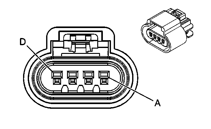
|
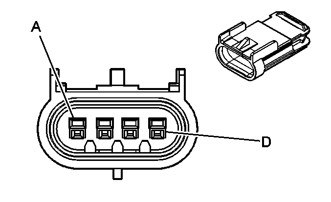
|
Connector Part Information
| Connector Part Information
|
Terminal Part Information
| Terminal Part Information
|
Pin | Wire Color | Circuit No. | Function | Pin | Wire Color | Circuit No. | Function |
|---|---|---|---|---|---|---|---|
A | TN/BK | 2500 | High Speed GMLAN Serial Data Bus+ | A | TN/BK | 2500 | High Speed GMLAN Serial Data Bus+ |
B | TN | 2501 | High Speed GMLAN Serial Data Bus- | B | TN | 2501 | High Speed GMLAN Serial Data Bus- |
C | L-GN | 24 | Backup Lamp Supply Voltage | C | L-GN | 24 | Backup Lamp Supply Voltage |
D | BN | 4 | Accessory Voltage | D | BN | 4 | Accessory Voltage |
C102 Engine Harness to the Crankshaft Position Jumper(L61)
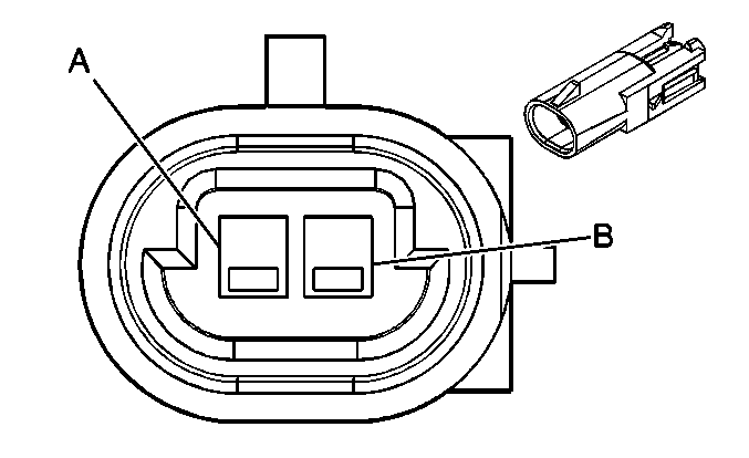
|
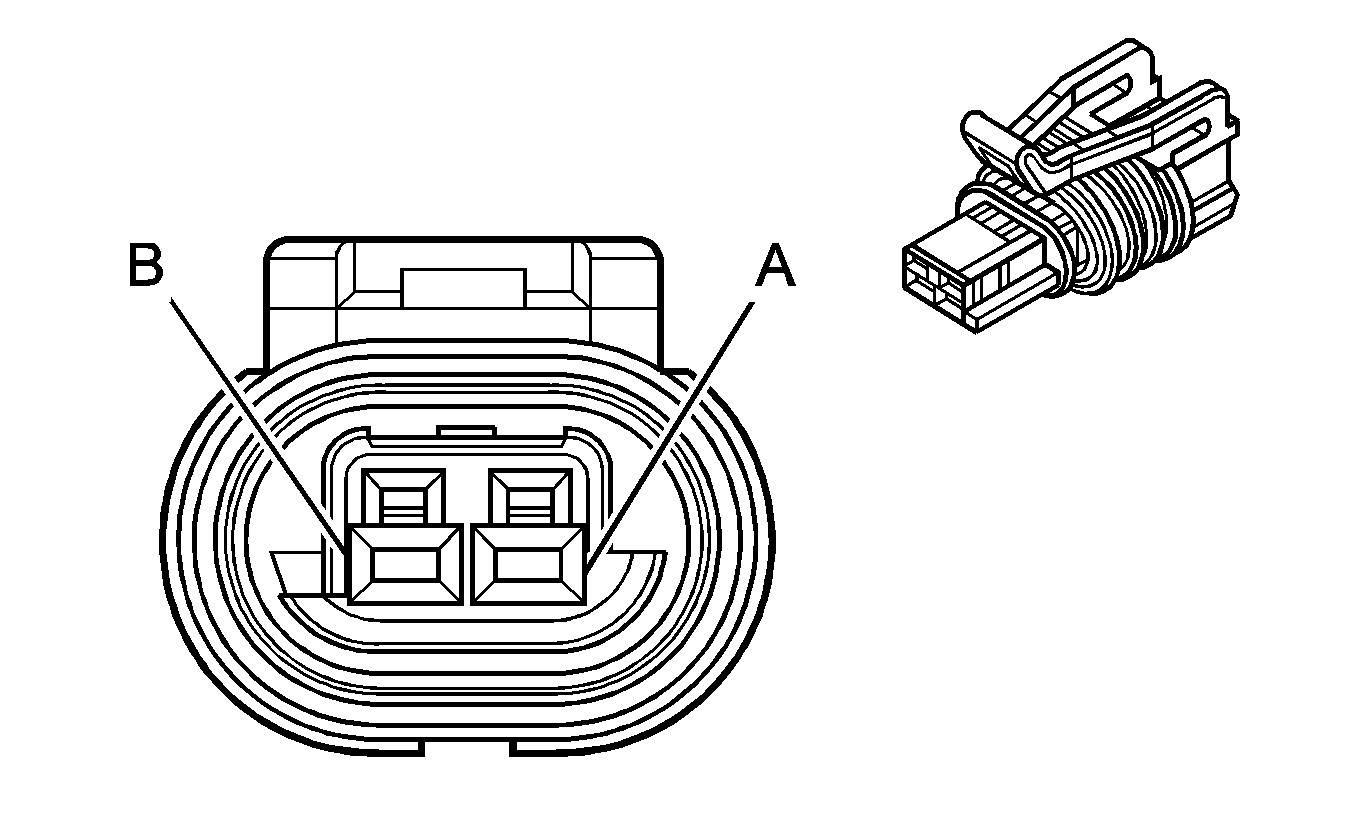
|
Connector Part Information
| Connector Part Information
|
Terminal Part Information
| Terminal Part Information
|
Pin | Wire Color | Circuit No. | Function | Pin | Wire Color | Circuit No. | Function |
|---|---|---|---|---|---|---|---|
A | PU | 574 | Low Reference | A | PU | 574 | Low Reference |
B | YE | 573 | CKP Sensor Signal | B | YE | 573 | CKP Sensor Signal |
C102 Engine Harness to the Crankshaft Position Jumper(LSJ)
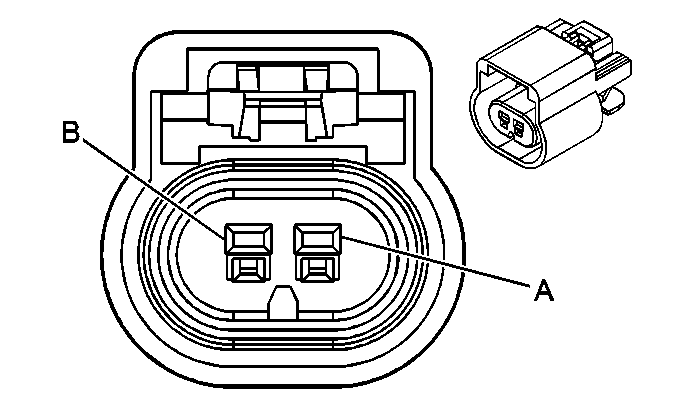
|
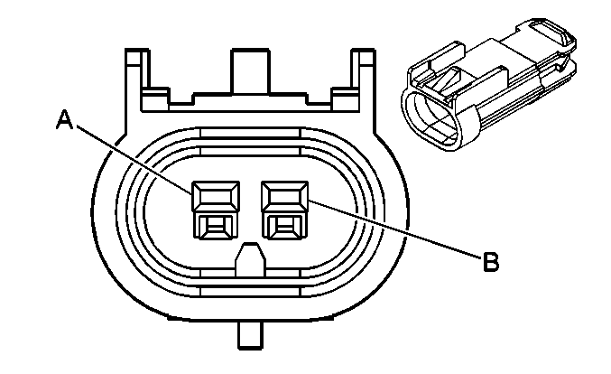
|
Connector Part Information
| Connector Part Information
|
Terminal Part Information
| Terminal Part Information
|
Pin | Wire Color | Circuit No. | Function | Pin | Wire Color | Circuit No. | Function |
|---|---|---|---|---|---|---|---|
A | PU | 574 | Low Reference | A | PU | 574 | Low Reference |
B | YE | 573 | CKP Sensor [1] Signal | B | YE | 573 | CKP Sensor [1] Signal |
C110 Forward Lamp Harness to the Right Headlamp Assembly
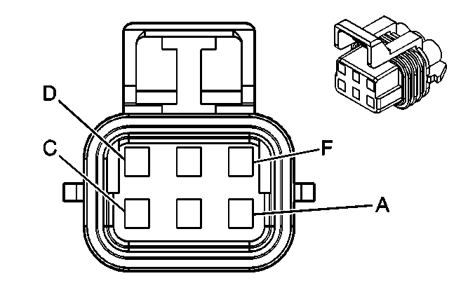
|
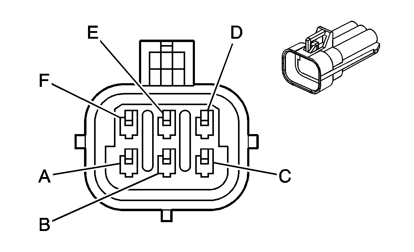
|
Connector Part Information
| Connector Part Information
|
Terminal Part Information
| Terminal Part Information
|
Pin | Wire Color | Circuit No. | Function | Pin | Wire Color | Circuit No. | Function |
|---|---|---|---|---|---|---|---|
A | BK | 250 | Ground | A | BK | 250 | Ground |
B | D-BU | 15 | Right Turn Signal Lamp Supply Voltage | B | L-BU | 15 | Right Turn Signal Lamp Supply Voltage |
C | BN | 9 | Park Lamp Supply Voltage | C | BN | 9 | Park Lamp Supply Voltage |
D | TN/WH | 312 | Right Headlamp Low Beam Supply Voltage | D | OG | 312 | Right Headlamp Low Beam Supply Voltage |
E | L-GN/BK | 311 | Right Headlamp High Beam Supply Voltage | E | PK | 311 | Right Headlamp High Beam Supply Voltage |
F | -- | -- | Not Used | F | -- | -- | Not Used |
C111 Forward Lamp Harness to the Left Headlamp Assembly

|

|
Connector Part Information
| Connector Part Information
|
Terminal Part Information
| Terminal Part Information
|
Pin | Wire Color | Circuit No. | Function | Pin | Wire Color | Circuit No. | Function |
|---|---|---|---|---|---|---|---|
A | BK | 150 | Ground | A | BK | 150 | Ground |
B | L-BU | 14 | Left Turn Signal Lamp Supply Voltage | B | L-BU | 14 | Left Turn Signal Lamp Supply Voltage |
C | BN | 9 | Park Lamp Supply Voltage | C | BN | 9 | Park Lamp Supply Voltage |
D | YE | 712 | Left Headlamp Low Beam Supply Voltage | D | OG | 712 | Left Headlamp Low Beam Supply Voltage |
E | D-GN/WH | 711 | Left Headlamp High Beam Supply Voltage | E | PK | 711 | Left Headlamp High Beam Supply Voltage |
F | -- | -- | Not Used | F | -- | -- | Not Used |
C121 Forward Lamp Harness to the Body Harness

|

|
Connector Part Information
| Connector Part Information
|
Terminal Part Information
| Terminal Part Information
|
Pin | Wire Color | Circuit No. | Function | Pin | Wire Color | Circuit No. | Function |
|---|---|---|---|---|---|---|---|
A | YE | 1834 | Forward Discriminating Sensor Signal | A | YE | 1834 | Forward Discriminating Sensor Signal |
B | TN/OG | 5045 | Discriminating Sensor - Low Reference | B | TN/OG | 5045 | Discriminating Sensor - Low Reference |
C | D-GN/WH | 636 | Ambient Air Temperature Sensor Signal | C | D-GN/WH | 636 | Ambient Air Temperature Sensor Signal |
D | YE/BK | 61 | Low Reference | D | YE/BK | 61 | Low Reference |
C160 Engine Harness to the Fuel Injector Harness (L61)
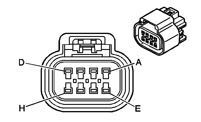
|
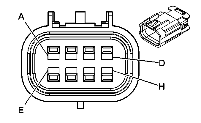
|
Connector Part Information
| Connector Part Information
|
Terminal Part Information
| Terminal Part Information
|
Pin | Wire Color | Circuit No. | Function | Pin | Wire Color | Circuit No. | Function |
|---|---|---|---|---|---|---|---|
A | TN | 1744 | Fuel Injector 1 Control | A | TN | 1744 | Fuel Injector 1 Control |
B | L-GN/BK | 1745 | Fuel Injector 2 Control | B | L-GN/BK | 1745 | Fuel Injector 2 Control |
C | PK/BK | 1746 | Fuel Injector 3 Control | C | PK/BK | 1746 | Fuel Injector 3 Control |
D | L-BU/BK | 844 | Fuel Injector 4 Control | D | L-BU/BK | 844 | Fuel Injector 4 Control |
E | PK/WH | 5292 | Ignition 1 Voltage | E | PK/WH | 5292 | Ignition 1 Voltage |
F | OG/BK | 469 | Low Reference | F | OG/BK | 469 | Low Reference |
G | L-GN | 432 | MAP Sensor Signal | G | L-GN | 432 | MAP Sensor Signal |
H | GY/BK | 2704 | 5-Volt Reference | H | GY/BK | 2704 | 5-Volt Reference |
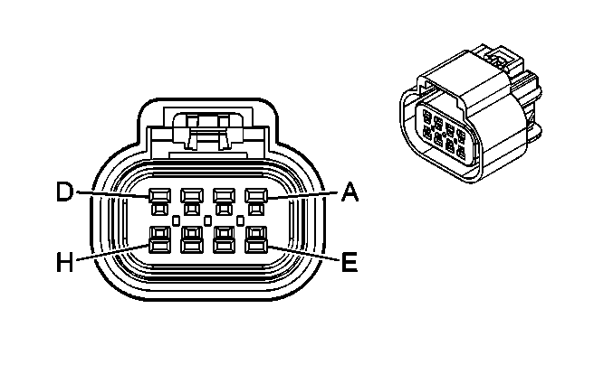
C161 Engine Harness to the Body Harness (LSJ)
|

|
Connector Part Information
| Connector Part Information
|
Terminal Part Information
| Terminal Part Information
|
Pin | Wire Color | Circuit No. | Function | Pin | Wire Color | Circuit No. | Function |
|---|---|---|---|---|---|---|---|
A | L-GN | 24 | Backup Lamp Supply Voltage | A | L-GN | 24 | Backup Lamp Supply Voltage |
B | L-BU | 6118 | IAT 2 Sensor Signal | B | L-BU | 6118 | IAT 2 Sensor Signal |
C | D-GN | 335 | Low Speed Cooling Fan Relay Control | C | D-GN | 335 | Low Speed Cooling Fan Relay Control |
D | TN | 891 | Boost Gage Signal | D | TN | 891 | Boost Gage Signal |
E | GY | 2700 | 5-Volt Reference | E | GY | 2700 | 5-Volt Reference |
F | RD/BK | 380 | A/C Refrigerant Pressure Sensor Signal | F | OG/BK | 380 | A/C Refrigerant Pressure Sensor Signal |
G | BK | 2751 | Ground | G | BK/WH | 2751 | Ground |
H | -- | -- | Not Used | H | -- | -- | Not Used |
C162 Engine Harness to the Ignition Coil Harness (LSJ)

|

|
Connector Part Information
| Connector Part Information
|
Terminal Part Information
| Terminal Part Information
|
Pin | Wire Color | Circuit No. | Function | Pin | Wire Color | Circuit No. | Function |
|---|---|---|---|---|---|---|---|
A | PK/WH | 5292 | Ignition 1 Voltage | A | PK/WH | 5292 | Ignition 1 Voltage |
B | PU | 6413 | Low Reference | B | PU | 6413 | Low Reference |
C | BN/WH | 6405 | IC 1 Control | C | BN/WH | 6405 | IC 1 Control |
D | D-BU/WH | 6406 | IC 3 Control | D | D-BU/WH | 6406 | IC 3 Control |
E | D-GN/WH | 6407 | IC 4 Control | E | D-GN/WH | 6407 | IC 4 Control |
F | L-BU/WH | 6408 | IC 2 Control | F | L-BU/WH | 6408 | IC 2 Control |
G | BK | 1350 | Ground | G | BK | 1350 | Ground |
H | -- | -- | Not Available | H | -- | -- | Not Available |
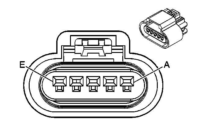
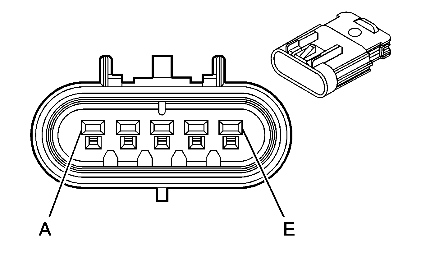
C164 Engine Harness to the Fuel Injector Harness (LSJ)
|
|
Connector Part Information
| Connector Part Information
|
Terminal Part Information
| Terminal Part Information
|
Pin | Wire Color | Circuit No. | Function | Pin | Wire Color | Circuit No. | Function |
|---|---|---|---|---|---|---|---|
A | PK/WH | 5292 | Ignition 1 Voltage | A | PK/WH | 5292 | Ignition 1 Voltage |
B | BK | 1744 | Fuel Injector 1 Control | B | BK | 1744 | Fuel Injector 1 Control |
C | L-GN/BK | 1745 | Fuel Injector 2 Control | C | L-GN/BK | 1745 | Fuel Injector 2 Control |
D | PK/BK | 1746 | Fuel Injector 3 Control | D | PK/BK | 1746 | Fuel Injector 3 Control |
E | L-BU/BK | 844 | Fuel Injector 4 Control | E | L-BU/BK | 844 | Fuel Injector 4 Control |
C170 Body Harness to the RF WSS Harness

|

|
Connector Part Information
| Connector Part Information
|
Terminal Part Information
| Terminal Part Information
|
Pin | Wire Color | Circuit No. | Function | Pin | Wire Color | Circuit No. | Function |
|---|---|---|---|---|---|---|---|
A | D-GN | 872 | Right Front Wheel Speed Sensor Signal | A | D-GN | 872 | Right Front Wheel Speed Sensor Signal |
B | TN | 833 | Right Front Wheel Speed Sensor Low Reference | B | TN | 833 | Right Front Wheel Speed Sensor Low Reference |
C171 Body Harness to the LF WSS Harness

|

|
Connector Part Information
| Connector Part Information
|
Terminal Part Information
| Terminal Part Information
|
Pin | Wire Color | Circuit No. | Function | Pin | Wire Color | Circuit No. | Function |
|---|---|---|---|---|---|---|---|
A | L-BU | 830 | Left Front Wheel Speed Sensor Signal | A | D-GN | 872 | Left Front Wheel Speed Sensor Signal |
B | YE | 873 | Left Front Wheel Speed Sensor Low Reference | B | TN | 833 | Left Front Wheel Speed Sensor Low Reference |
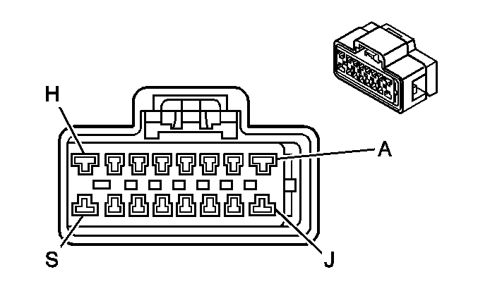
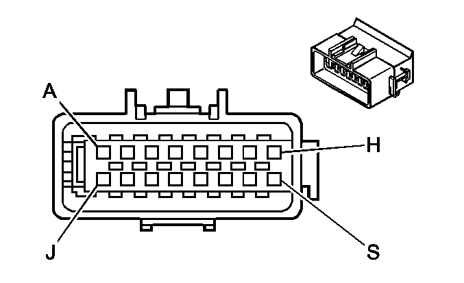
C200 I/P Harness to the Body Harness
|
|
Connector Part Information
| Connector Part Information
|
Terminal Part Information
| Terminal Part Information
|
Pin | Wire Color | Circuit No. | Function | Pin | Wire Color | Circuit No. | Function |
|---|---|---|---|---|---|---|---|
A | PK/BK | 1503 | Passenger Heated Seat High/Low Signal | A | PK/BK | 1503 | Passenger Heated Seat High/Low Signal |
B | L-BU/BK | 1505 | Passenger Heated Seat Switch Signal | B | L-BU/BK | 1505 | Passenger Heated Seat Switch Signal |
C-D | -- | -- | Not Used | C-D | -- | -- | Not Used |
E | L-GN | 200 | Right Front Speaker Output (+) | E | L-GN/BK | 200 | Right Front Speaker Output (+) (UQ3) |
L-GN | 200 | Right Front Speaker (+) Output (UQ4) | |||||
F | D-GN | 117 | Right Front Speaker Output (-) | F | D-GN/BK | 117 | Right Front Speaker Output (-) (UQ3) |
D-GN | 117 | Right Front Speaker Output l (-) (UQ4) | |||||
G | L-BU/BK | 115 | Right Rear Speaker Output (-) (UQ3) | G | L-BU/BK | 115 | Right Rear Speaker Output (-) (UQ3) |
G | L-BU | 115 | Right Rear Speaker Output (-) (UQ4) | G | L-BU | 115 | Right Rear Speaker Output (-) (UQ4) |
H | D-BU | 46 | Right Rear Speaker Output (+) | H | D-BU.BK | 46 | Right Rear Speaker Output (+) (UQ3) |
D-BU | 46 | Right Rear Speaker Output (+) (UQ4) | |||||
J | BARE | 814 | Drain Wire (U2K) | J | BARE | 814 | Drain Wire (U2K) |
K | BN/WH | 367 | Left Audio Signal (+) (U2K) | K | BN/WH | 367 | Left Audio Signal (+) (U2K) |
L | D-GN/WH | 368 | Right Audio Signal (+) (U2K) | L | D-GN/WH | 368 | Right Audio Signal (+) (U2K) |
M | TN/WH | 372 | Audio Common (U2K) | M | TN/WH | 372 | Audio Common (U2K) |
N-S | -- | -- | Not Used | N-S | -- | -- | Not Used |
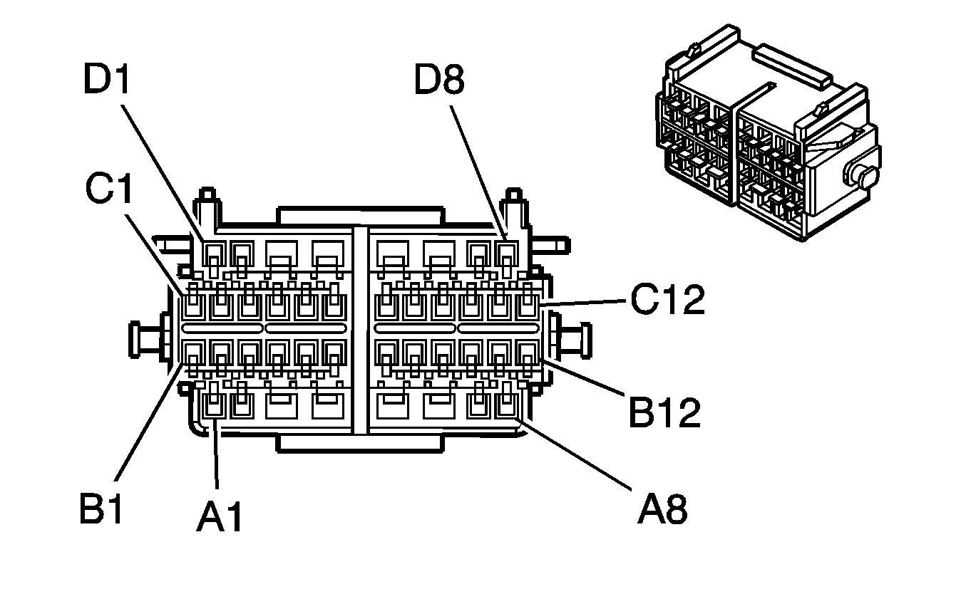
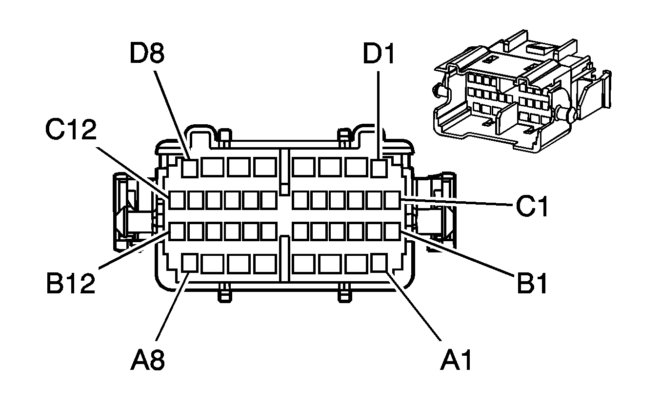
C201 I/P Harness to the Body Harness
|
|
Connector Part Information
| Connector Part Information
|
Terminal Part Information
| Terminal Part Information
|
Pin | Wire Color | Circuit No. | Function | Pin | Wire Color | Circuit No. | Function |
|---|---|---|---|---|---|---|---|
A1 | L-BU | 1162 | APP Sensor 2 Signal | A1 | L-BU | 1162 | APP Sensor 2 Signal |
A2 | D-BU | 1161 | APP Sensor 1 Signal | A2 | D-BU | 1161 | APP Sensor 1 Signal |
A3 | OG/BK | 2061 | Cellular Telephone Voice Low Reference | A3 | OG/BK | 2061 | Cellular Telephone Voice Low Reference |
A4 | -- | -- | Not Used | A4 | -- | -- | Not Used |
A5 | GY | 118 | Left Front Speaker Output (-) | A5 | GY | 118 | Left Front Speaker Output (-) (UQ4) |
GY/BK | 118 | Left Front Speaker Output (- ) (UQ3) | |||||
A6 | PK | 339 | Ignition 1 Voltage | A6 | PK | 339 | Ignition 1 Voltage |
A7 | D-GN | 5060 | Low Speed GMLAN Serial Data | A7 | D-GN | 5060 | Low Speed GMLAN Serial Data |
A8 | -- | -- | Not Used | A8 | -- | -- | Not Used |
B1 | PU | 1272 | Low Reference | B1 | PU | 1272 | Low Reference |
B2 | BN | 1271 | Low Reference | B2 | BN | 1271 | Low Reference |
B3 | BARE | 813 | Drain Wire | B3 | BARE | 813 | Drain Wire |
B4 | PK/BK | 2062 | Cellular Telephone Voice Signal | B4 | PK/BK | 2062 | Cellular Telephone Voice Signal |
B5 | YE | 575 | Starter Control | B5 | YE | 575 | Starter Control |
B6 | PK/BK | 5291 | Ignition 1 Voltage | B6 | PK/BK | 5291 | Ignition 1 Voltage |
B7 | D-BU/WH | 346 | Rear Subwoofer Speaker Output (+) | B7 | D-BU/WH | 346 | Rear Subwoofer Speaker Output (+) |
B8 | TN | 1274 | 5-Volt Reference | B8 | TN | 1274 | 5-Volt Reference |
B9 | BN/WH | 379 | CPP Switch Signal | B9 | BN/WH | 379 | CPP Switch Signal |
B10 | L-GN/BK | 1794 | Rear Subwoofer Speaker Output (-) | B10 | L-GN/BK | 1794 | Rear Subwoofer Speaker Output (-) |
B11 | WH/BK | 1164 | 5-Volt Reference | B11 | WH/BK | 1164 | 5-Volt Reference |
B12 | -- | -- | Not Used | B12 | -- | -- | Not Used |
C1 | PK | 1501 | Driver Heated Seat High/Low Signal | C1 | PK | 1501 | Driver Heated Seat High/Low Signal |
C2 | TN | 891 | Boost Gauge Signal | C2 | TN | 891 | Boost Gauge Signal |
C3 | PU | 420 | TCC Brake Switch/Cruise Control Release Signal | C3 | PU | 420 | TCC Brake Switch/Cruise Control Release Signal |
C4 | L-BU | 1462 | Heated Seat Switch Signal | C4 | L-BU | 1462 | Heated Seat Switch Signal |
C5 | TN/BK | 2500 | High Speed GMLAN Serial Data Bus+ | C5 | TN/BK | 2500 | High Speed GMLAN Serial Data Bus+ |
C6 | TN | 2501 | High Speed GMLAN Serial Data Bus- | C6 | TN | 2501 | High Speed GMLAN Serial Data Bus- |
C7 | -- | -- | Not Used | C7 | D-GN | 1049 | Not Used |
C8 | BN/WH | 419 | MIL Control | C8 | BN/WH | 419 | MIL Control |
C9 | L-GN | 1715 | Windshield Wiper Switch High Signal | C9 | L-GN | 1715 | Windshield Wiper Switch High Signal |
C10 | PK/WH | 1970 | Headlamp Low Beam Relay Control | C10 | PK/WH | 1970 | Headlamp Low Beam Relay Control |
C11 | YE | 116 | Left Rear Speaker Output (-) | C11 | YE | 116 | Left Rear Speaker Output (-) (UQ4) |
YE/BK | 116 | Left Rear Speaker Output (-) (UQ3) | |||||
C12 | BN | 199 | Left Rear Speaker Output (+) | C12 | BN | 199 | Left Rear Speaker Output (+) (UQ4) |
BN/BK | 199 | Left Rear Speaker Output (+) (UQ3) | |||||
D1 | TN | 201 | Left Front Speaker Output (+) | D1 | TN/BK | 201 | Left Front Speaker Output (+) (UQ3) |
TN | 201 | Left Front Speaker Output (+) (UQ4) | |||||
D2 | -- | -- | Not Used | D2 | -- | -- | Not Used |
D3 | RD/WH | 40 | Battery Positive Voltage | D3 | RD/WH | 40 | Battery Positive Voltage |
D3 | RD/WH | 40 | Battery Positive Voltage | ||||
D4 | -- | -- | Not Used | D4 | L-BU | 20 | Stop Lamp Switch Signal |
D5 | -- | -- | Not Used | D5 | -- | -- | Not Used |
D6 | L-BU/BK | 315 | Right Subwoofer Speaker Output (-) | D6 | L-BU/BK | 315 | Right Subwoofer Speaker Output (-) |
D7 | D-GN | 1795 | Right Subwoofer Speaker Output (+) | D7 | D-GN | 1795 | Right Subwoofer Speaker Output (+) |
D8 | D-GN/WH | 1932 | Ignition Lock Cylinder Control Actuator Signal | D8 | D-GN/WH | 1932 | Ignition Lock Cylinder Control Actuator Signal |
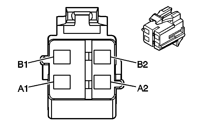
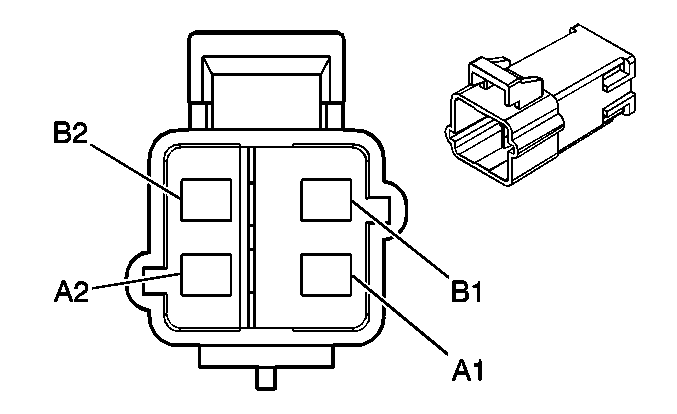
C202 Passenger Inflatable Restraint I/P Module to the Body Harness
|
|
Connector Part Information
| Connector Part Information
|
Terminal Part Information
| Terminal Part Information
|
Pin | Wire Color | Circuit No. | Function | Pin | Wire Color | Circuit No. | Function |
|---|---|---|---|---|---|---|---|
A1 | L-GN/OG | 3024 | I/P Module Stage 1 Low Control | A1 | OG | 3024 | I/P Module Stage 1 Low Control |
A2 | RD/WH | 3025 | I/P Module Stage 1 High Control | A2 | YE | 3025 | I/P Module Stage 1 High Control |
B1 | PK/BK | 3026 | I/P Module Stage 2 Low Control | B1 | PU | 3026 | I/P Module Stage 2 Low Control |
B2 | L-BU/OG | 3027 | I/P Module Stage 2 High Control | B2 | GY | 3027 | I/P Module Stage 2 High Control |
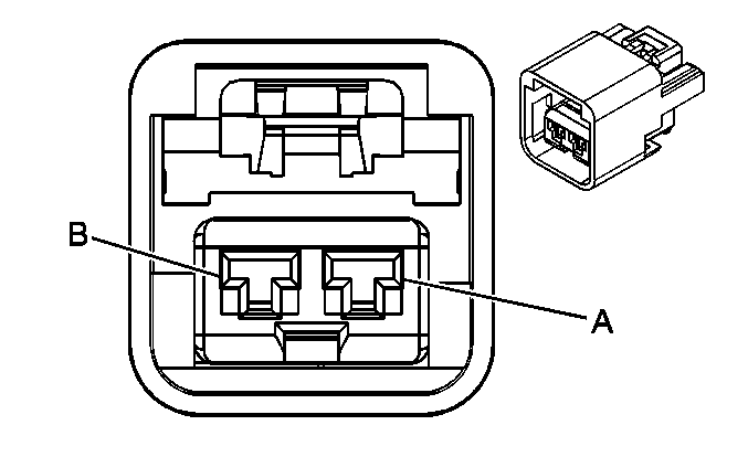
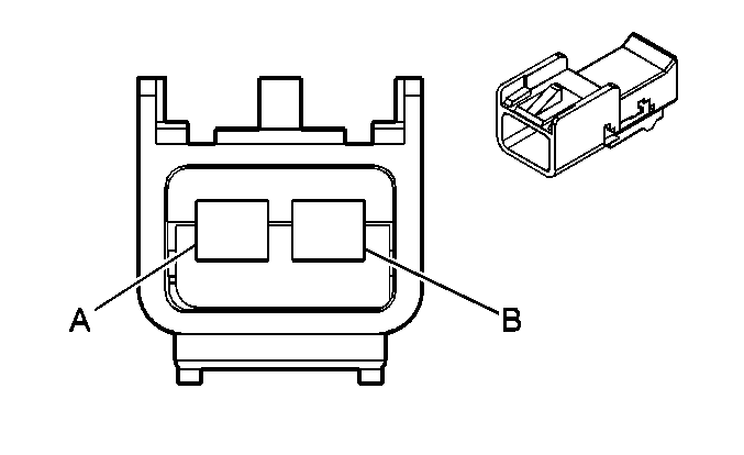
C210 I/P Harness to the HVAC Harness
|
|
Connector Part Information
| Connector Part Information
|
Terminal Part Information
| Terminal Part Information
|
Pin | Wire Color | Circuit No. | Function | Pin | Wire Color | Circuit No. | Function |
|---|---|---|---|---|---|---|---|
A | BK | 550 | Ground | A | BK | 550 | Ground |
B | BN | 141 | Ignition 3 Voltage | B | BN | 141 | Ignition 3 Voltage |
C275 I/P Harness to the SIR Coil Assembly

|

|
Connector Part Information
| Connector Part Information
|
Terminal Part Information
| Terminal Part Information
|
Pin | Wire Color | Circuit No. | Function | Pin | Wire Color | Circuit No. | Function |
|---|---|---|---|---|---|---|---|
A1 | BN | 3020 | Steering Wheel Module - Stage1 - Low Control | A1 | BN | 3020 | Steering Wheel Module - Stage1 - Low Control |
A2 | TN | 3021 | Steering Wheel Module - Stage1 - High Control | A2 | TN | 3021 | Steering Wheel Module - Stage1 - High Control |
B1 | PK | 3022 | Steering Wheel Module - Stage2 - Low Control | B1 | PK | 3022 | Steering Wheel Module - Stage2 - Low Control |
B2 | WH | 3023 | Steering Wheel Module - Stage2 - High Control | B2 | WH | 3023 | Steering Wheel Module - Stage2 - High Control |
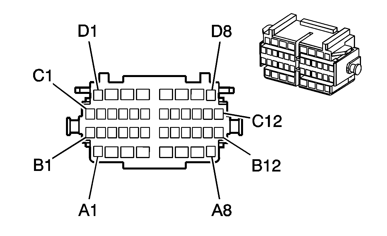
C300 Body Harness to the Passenger Door Harness
|

|
Connector Part Information
| Connector Part Information
|
Terminal Part Information
| Terminal Part Information
|
Pin | Wire Color | Circuit No. | Function | Pin | Wire Color | Circuit No. | Function |
|---|---|---|---|---|---|---|---|
A1 | -- | -- | Not Used | A1 | -- | -- | Not Used |
A2 | GY | 8 | Instrument Panel Lamp Supply Voltage (1) | A2 | GY | 8 | Instrument Panel Lamp Supply Voltage (1) |
A3-A8 | -- | -- | Not Used | A3-A8 | -- | -- | Not Used |
B1-B2 | -- | -- | Not Used | B1-B2 | -- | -- | Not Used |
B3 | WH | 682 | Door Lock Lock/Unlock Signal | B3 | WH | 682 | Door Lock Lock/Unlock Signal |
B4 | -- | -- | Not Used | B4 | -- | -- | Not Used |
B5 | TN | 294 | Door Lock Actuator Unlock Control | B5 | TN | 294 | Door Lock Actuator Unlock Control |
B6 | GY | 295 | Door Lock Actuator Lock Control | B6 | GY | 295 | Door Lock Actuator Lock Control |
B7 | OG/WH | 881 | Right Mirror Motor Right Control | B7 | OG/WH | 881 | Right Mirror Motor Right Control |
B8 | PU/WH | 889 | Right Mirror Motor Down Control | B8 | PU/WH | 889 | Right Mirror Motor Down Control |
B9-B10 | -- | -- | Not Used | B9-B10 | -- | -- | Not Used |
B11 | D-GN | 2134 | Right Front Side Impact Sensing Module Signal | B11 | D-GN | 2134 | Right Front Side Impact Sensing Module Signal |
B12 | TN | 2133 | Right Front Side Impact Sensing Module Supply Voltage | B12 | TN | 2133 | Right Front Side Impact Sensing Module Supply Voltage |
C1-C6 | -- | -- | Not Used | C1-C6 | -- | -- | Not Used |
C7 | WH | 330 | Right Mirror Motor Supply Voltage | C7 | WH | 330 | Right Mirror Motor Supply Voltage |
C8-C12 | -- | -- | Not Used | C8-C12 | -- | -- | Not Used |
D1 | -- | -- | Not Used | D1 | -- | -- | Not Used |
D2 | L-BU | 166 | Power Window Master Switch Right Front Up Signal | D2 | L-BU | 166 | Power Window Master Switch Right Front Up Signal |
D3 | TN | 167 | Power Window Master Switch Right Front Down Signal | D3 | TN | 167 | Power Window Master Switch Right Front Down Signal |
D4 | D-GN/BK | 117 | Right Front Speaker Output (-) (UQ3) | D4 | D-GN | 117 | Right Front Speaker Output (-) (UQ3) |
D4 | D-GN/WH | 117 | Right Front Speaker Output (-) (UQ3) | ||||
D4 | D-GN | 117 | Right Front Speaker Output (-) (UQ4) | D4 | D-GN | 117 | Right Front Speaker Output (-) (UQ4) |
D5 | L-GN/BK | 200 | Right Front Speaker Output (+) (UQ3) | D5 | L-GN | 200 | Right Front Speaker Output (+) (UQ3) |
D5 | L-GN | 200 | Right Front Speaker Output (+) (UQ3) | ||||
D5 | L-GN | 200 | Right Front Speaker Output (+) (UQ4) | D5 | L-GN | 200 | Right Front Speaker Output (+) (UQ4) |
D6 | BK | 650 | Ground | D6 | BK | 650 | Ground |
D7 | D-GN | 801 | Retained Accessory Power Fuse Supply Voltage | D7 | D-GN | 801 | Retained Accessory Power Fuse Supply Voltage |
D8 | -- | -- | Not Used | D8 | -- | -- | Not Used |
C301 Body Harness to the Driver Door Harness

|

|
Connector Part Information
| Connector Part Information
|
Terminal Part Information
| Terminal Part Information
|
Pin | Wire Color | Circuit No. | Function | Pin | Wire Color | Circuit No. | Function |
|---|---|---|---|---|---|---|---|
A1 | GY | 8 | Instrument Panel Lamp Supply Voltage | A1 | GY | 8 | Instrument Panel Lamp Supply Voltage |
A2 | GY | 8 | Instrument Panel Lamp Supply Voltage | A2 | GY | 8 | Instrument Panel Lamp Supply Voltage |
A3 | D-BU | 1307 | Power Window Master Switch Lockout Signal (Sedan) | A3 | D-BU | 1307 | Power Window Master Switch Lockout Signal (Sedan) |
A4 | GY/BK | 118 | Left Front Speaker Output (-) (UQ3) | A4 | GY/BK | 118 | Left Front Speaker Output (-) (UQ3) |
A4 | GY | 118 | Left Front Speaker Output (-) (UQ3) | ||||
A4 | GY | 118 | Left Front Speaker Output (-) (UQ4) | A4 | GY | 118 | Left Front Speaker Output (-) (UQ4) |
A5 | TN/BK | 201 | Left Front Speaker Output (+) (UQ3) | A5 | TN | 201 | Left Front Speaker Output (+) (UQ3) |
A5 | TN | 201 | Left Front Speaker Output (+) (UQ3) | ||||
A5 | TN | 201 | Left Front Speaker Output (+) (UQ4) | A5 | TN | 201 | Left Front Speaker Output (+) (UQ4) |
A6 | BK | 650 | Ground | A6 | BK | 650 | Ground |
A7 | D-GN | 801 | RAP Fuse Supply Voltage | A7 | D-GN | 801 | RAP Fuse Supply Voltage |
A8 | -- | -- | Not Used | A8 | -- | -- | Not Used |
B1-B2 | -- | -- | Not Used | B1-B2 | -- | -- | Not Used |
B3 | WH | 682 | Door Lock Lock/Unlock Signal | B3 | WH | 682 | Door Lock Lock/Unlock Signal |
B4 | -- | -- | Not Used | B4 | -- | -- | Not Used |
B5 | TN | 694 | Driver Door Lock Actuator Unlock Control | B5 | TN | 694 | Driver Door Lock Actuator Unlock Control |
B6 | GY | 295 | Door Lock Actuator Lock Control | B6 | GY | 295 | Door Lock Actuator Lock Control |
B7-B10 | -- | -- | Not Used | B7-B10 | -- | -- | Not Used |
B11 | WH | 2132 | Side Impact Sensing Module - Left - Signal | B11 | WH | 2132 | Side Impact Sensing Module - Left - Signal |
B12 | YE | 2131 | Side Impact Sensing Module - Left -Voltage | B12 | YE | 2131 | Side Impact Sensing Module - Left -Voltage |
C1-C2 | -- | -- | Not Used | C1-C2 | -- | -- | Not Used |
C3 | RD/WH | 440 | Battery Positive Voltage | C3 | RD/WH | 440 | Battery Positive Voltage |
C4-C5 | -- | -- | Not Used | C4-C5 | -- | -- | Not Used |
C6 | PU/WH | 889 | Passenger Mirror Motor Down Control | C6 | PU/WH | 889 | Passenger Mirror Motor Down Control |
C7 | WH | 330 | Passenger Mirror Motor Supply Voltage | C7 | WH | 330 | Passenger Mirror Motor Supply Voltage (Coupe) |
WH/BK | 330 | Passenger Mirror Motor Supply Voltage (Sedan) | |||||
C8 | OG/WH | 881 | Passenger Mirror Motor Right Control | C8 | OG/WH | 881 | Passenger Mirror Motor Right Control |
C9-C12 | -- | -- | Not Used | C9-C12 | -- | -- | Not Used |
D1 | -- | -- | Not Used | D1 | -- | -- | Not Used |
D2 | L-BU | 166 | Power Window Master Switch Right Front Up Signal | D2 | L-BU | 166 | Power Window Master Switch Right Front Up Signal |
D3 | TN | 167 | Power Window Master Switch Right Front Down Signal | D3 | TN | 167 | Power Window Master Switch Right Front Down Signal |
D4 | D-GN | 168 | Power Window Master Switch Left Rear Up Signal (Sedan) | D4 | D-GN/YE | 168 | Power Window Master Switch Left Rear Up Signal (Sedan) |
D5 | PU | 169 | Power Window Master Switch Left Rear Down Signal (Sedan) | D5 | PU | 169 | Power Window Master Switch Left Rear Down Signal (Sedan) |
D6 | L-GN | 170 | Power Window Master Switch Right Rear Up Signal (Sedan) | D6 | L-GN | 170 | Power Window Master Switch Right Rear Up Signal (Sedan) |
D7 | PU | 171 | Power Window Master Switch Right Rear Down Signal (Sedan) | D7 | PU/WH | 171 | Power Window Master Switch Right Rear Down Signal (Sedan) |
D8 | -- | -- | Not Used | D8 | -- | -- | Not Used |
C302 Headliner Harness to the Sun Roof Control Module
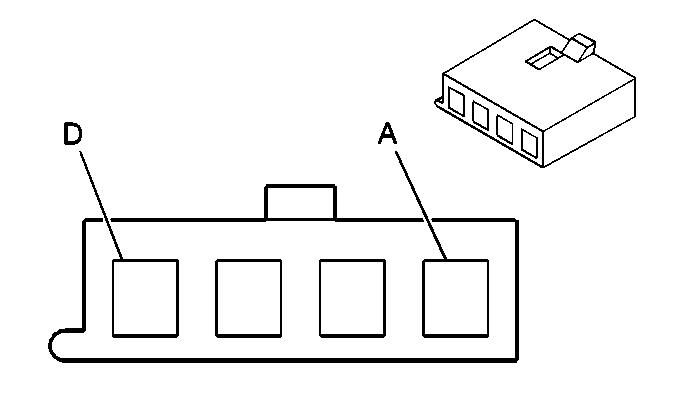
|
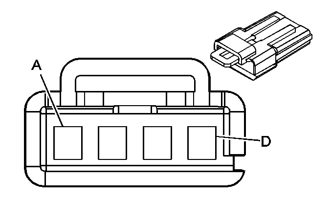
|
Connector Part Information
| Connector Part Information
|
Terminal Part Information
| Terminal Part Information
|
Pin | Wire Color | Circuit No. | Function | Pin | Wire Color | Circuit No. | Function |
|---|---|---|---|---|---|---|---|
A | BK | 750 | Ground | A | BK | 750 | Ground |
B | L-BU | 131 | Sunroof Limit Switch Range Signal | B | L-BU | 131 | Sunroof Limit Switch Range Signal |
C | L-GN | 129 | Sunroof Motor Close Control | C | L-GN | 129 | Sunroof Motor Close Control |
D | D-GN | 127 | Sunroof Motor Open Control | D | D-GN | 127 | Sunroof Motor Open Control |
C303 Body Harness to the RF Door Harness
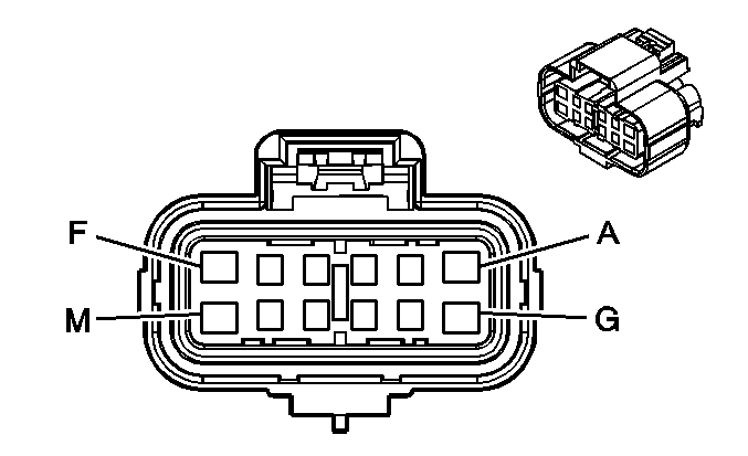
|
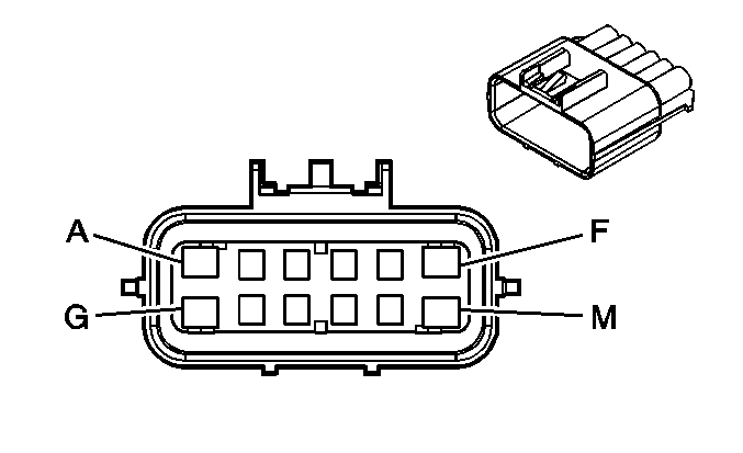
|
Connector Part Information
| Connector Part Information
|
Terminal Part Information
| Terminal Part Information
|
Pin | Wire Color | Circuit No. | Function | Pin | Wire Color | Circuit No. | Function |
|---|---|---|---|---|---|---|---|
A | BK | 650 | Ground | A | BK | 650 | Ground |
B | D-GN | 2134 | Side Impact Sensing Module - Right - Signal | B | D-GN | 2134 | Side Impact Sensing Module - Right - Signal |
C | TN | 2133 | Side Impact Sensing Module - Right - Voltage | C | TN | 2133 | Side Impact Sensing Module - Right - Voltage |
D | GY | 8 | Instrument Panel Lamp Supply Voltage | D | GY | 8 | Instrument Panel Lamp Supply Voltage |
E | WH | 682 | Door Lock Lock/Unlock Signal | E | WH | 682 | Door Lock Lock/Unlock Signal |
F | TN | 294 | Door Lock Actuator Unlock Control | F | TN | 294 | Door Lock Actuator Unlock Control |
G | GY | 295 | Door Lock Actuator Lock Control | G | GY | 295 | Door Lock Actuator Lock Control |
H -- J | -- | -- | Not Used | H | -- | -- | Not Used |
K | D-GN | 117 | Right Front Speaker Output (-) | K | D-GN | 117 | Right Front Speaker Output (-) |
L | L-GN | 200 | Right Front Speaker Output (+) | L | L-GN | 200 | Right Front Speaker Output (+) |
M | -- | -- | Not Used | M | -- | -- | Not Used |
C305 EVAP Canister Purge Jumper Harness/Fuel Tank Harness/Wheel Speed Sensor Harness to the Body Harness (w/ABS)
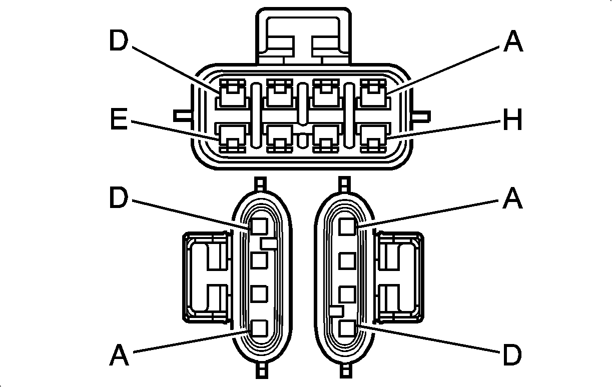
|
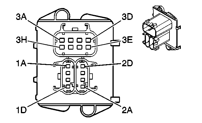
|
Connector Part Information
| Connector Part Information
|
Terminal Part Information
| Terminal Part Information
|
Pin | Wire Color | Circuit No. | Function | Pin | Wire Color | Circuit No. | Function |
|---|---|---|---|---|---|---|---|
1A | RD/WH | 1840 | Battery Positive Voltage | 1A | RD/WH | 1840 | Battery Positive Voltage |
1B | WH | 1310 | EVAP Canister Vent Solenoid Control | 1B | WH | 1310 | EVAP Canister Vent Solenoid Control |
1C | -- | -- | Not Used | 1C | -- | -- | Not Used |
1D | -- | -- | Not Used | 1D | -- | -- | Not Used |
2A | BN | 882 | Right Rear Wheel Speed Sensor Signal | 2A | BN | 882 | Right Rear Wheel Speed Sensor Signal |
2B | WH | 883 | Right Rear Wheel Speed Sensor Low 2BReference | B2 | WH | 883 | Right Rear Wheel Speed Sensor Low Reference |
2C | BK | 884 | Left Rear Wheel Speed Sensor Signal | 2C | TN | 884 | Left Rear Wheel Speed Sensor Signal |
2D | RD | 885 | Left Rear Wheel Speed Sensor Low Reference | 2D | OG | 885 | Left Rear Wheel Speed Sensor Low Reference |
3A | BK | 850 | Ground | A3 | BK | 850 | Ground |
3B | OG | 510 | Fuel Sender Low Reference | 3B | TN | 2759 | Fuel Sender Low Reference |
3C | GY | 120 | Fuel Pump Supply Voltage | 3C | GY | 120 | Fuel Pump Supply Voltage |
3D | PU | 1589 | Fuel Level Sensor Signal | 3D | PU | 1589 | Fuel Level Sensor Signal |
3E | -- | -- | Not Used | 3E | -- | -- | Not Used |
3F | GY/BK | 2709 | 5-Volt Reference | 3F | GY | 2709 | 5-Volt Reference |
3G | D-GN | 890 | Fuel Tank Pressure Sensor Signal | 3G | D-GN | 890 | Fuel Tank Pressure Sensor Signal |
H3 | BK/WH | 2759 | Fuel Tank Pressure Sensor Low Reference (2.2L/2.4L) | H3 | TN | 2759 | Fuel Tank Pressure Sensor Low Reference (2.2L/2.4L) |
H3 | TN | 2759 | Fuel Tank Pressure Sensor Low Reference (2.2L/2.4L) |
C305 EVAP Canister Purge Jumper Harness/Fuel Tank Harness/Wheel Speed Sensor Harness to the Body Harness (w/oABS)
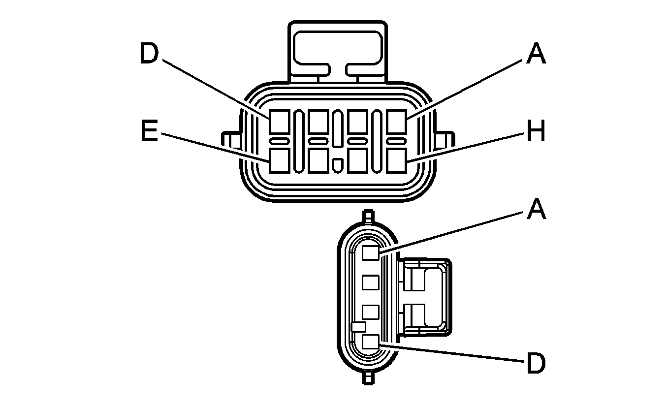
|
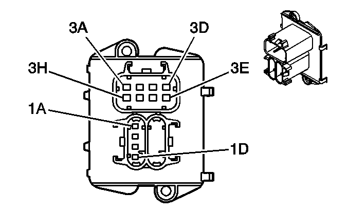
|
Connector Part Information
| Connector Part Information
|
Terminal Part Information
Connector Part Information
Terminal Part Information
| Terminal Part Information
|
Pin | Wire Color | Circuit No. | Function | Pin | Wire Color | Circuit No. | Function |
|---|---|---|---|---|---|---|---|
1A | RD/WH | 1840 | Battery Positive Voltage | 1A | RD/WH | 1840 | Battery Positive Voltage |
1B | WH | 1310 | EVAP Canister Vent Solenoid Control | 1B | WH | 1310 | EVAP Canister Vent Solenoid Control |
1C | -- | -- | Not Used | 1C | -- | -- | Not Used |
1D | -- | -- | Not Used | 1D | -- | -- | Not Used |
3A | BK | 850 | Ground | A3 | BK | 850 | Ground |
3B | OG | 510 | Fuel Sender Low Reference | 3B | TN | 2759 | Fuel Sender Low Reference |
3C | GY | 120 | Fuel Pump Supply Voltage | 3C | GY | 120 | Fuel Pump Supply Voltage |
3D | PU | 1589 | Fuel Level Sensor Signal | 3D | PU | 1589 | Fuel Level Sensor Signal |
3E | -- | -- | Not Used | 3E | -- | -- | Not Used |
3F | GY/BK | 2709 | 5-Volt Reference | 3F | GY | 2709 | 5-Volt Reference |
3G | D-GN | 890 | Fuel Tank Pressure Sensor Signal | 3G | D-GN | 890 | Fuel Tank Pressure Sensor Signal |
H | BK/WH | 2759 | Fuel Tank Pressure Sensor Low Reference (2.2L/2.4L) | H3 | TN | 2759 | Fuel Tank Pressure Sensor Low Reference (2.2L/2.4L) |
H3 | TN | 2759 | Fuel Tank Pressure Sensor Low Reference (2.2L/2.4L) |
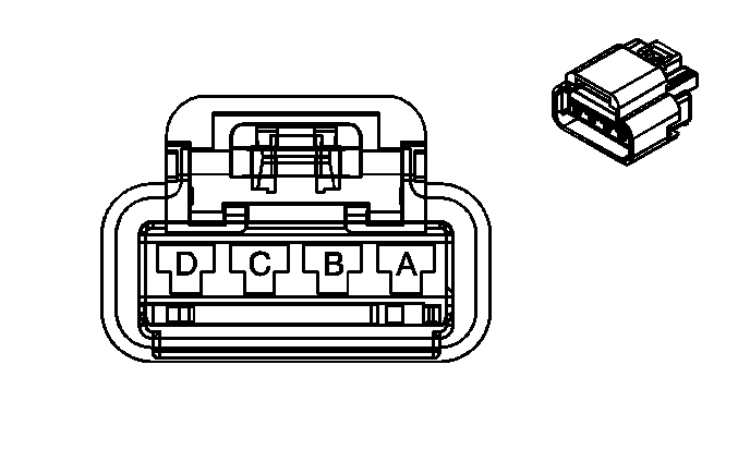
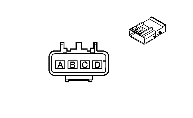
C314 Body Harness to the Passenger Seat Harness
|
|
Connector Part Information
| Connector Part Information
|
Terminal Part Information
| Terminal Part Information
|
Pin | Wire Color | Circuit No. | Function | Pin | Wire Color | Circuit No. | Function |
|---|---|---|---|---|---|---|---|
A | RD/WH | 340 | Battery Positive Voltage | A | RD/WH | 340 | Battery Positive Voltage |
B | L-BU/BK | 1505 | Passenger Heated Seat Switch Signal | B | L-BU/BK | 1505 | Passenger Heated Seat Switch Signal |
C | PK/BK | 1503 | Passenger Heated Seat High/Low Signal | C | PK/BK | 1503 | Passenger Heated Seat High/Low Signal |
D | BK | 1250 | Ground | D | BK | 1250 | Ground |
C315 Body Harness to the Driver Seat Harness

|

|
Connector Part Information
| Connector Part Information
|
Terminal Part Information
| Terminal Part Information
|
Pin | Wire Color | Circuit No. | Function | Pin | Wire Color | Circuit No. | Function |
|---|---|---|---|---|---|---|---|
A | RD/WH | 340 | Battery Positive Voltage | A | RD/WH | 340 | Battery Positive Voltage |
B | L-BU | 1462 | Heated Seat Switch Signal | B | L-BU | 1462 | Heated Seat Switch Signal |
C | PK | 1501 | Driver Heated Seat High/Low Signal | C | PK | 1501 | Driver Heated Seat High/Low Signal |
D | BK | 1250 | Ground | D | BK | 1250 | Ground |
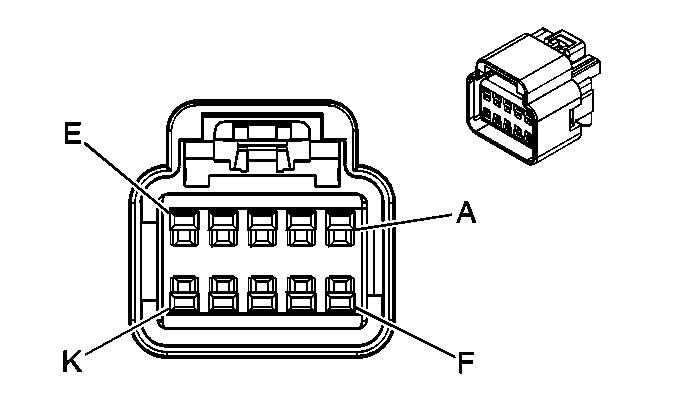
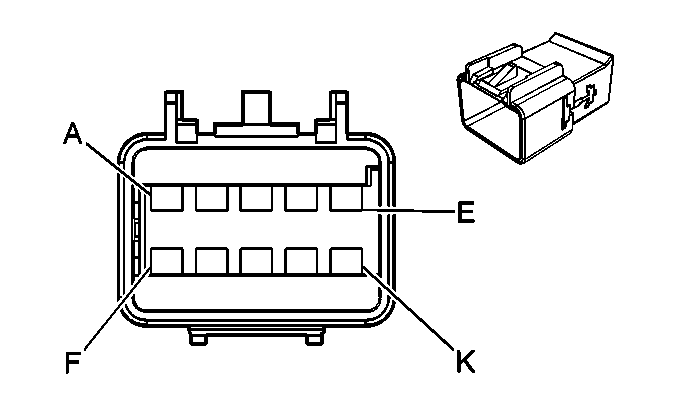
C316 Body Harness to the Passenger Seat Harness
|
|
Connector Part Information
| Connector Part Information
|
Terminal Part Information
| Terminal Part Information
|
Pin | Wire Color | Circuit No. | Function | Pin | Wire Color | Circuit No. | Function |
|---|---|---|---|---|---|---|---|
A | OG | 1362 | Seat Belt Switch - Right - Signal | A | OG | 1362 | Seat Belt Switch - Right - Signal |
B | PK | 915 | 5-Volt Reference | B | PK | 915 | 5-Volt Reference (Early Production) |
PK/BK | 915 | 5-Volt Reference (Late Production) | |||||
C | PK | 5057 | Low Reference | C | PK | 5057 | Low Reference (Early Production) |
BN | 5057 | Low Reference (Late Production) | |||||
D | PK | 353 | Passenger Air Bag Off Indicator Control | D | PK | 353 | Passenger Air Bag Off Indicator Control |
E | TN/BK | 723 | Passenger Air Bag On Indicator Control | E | TN/BK | 723 | Passenger Air Bag On Indicator Control |
F | YE | 914 | Low Reference | F | YE | 914 | Low Reference |
G | PK | 1339 | Ignition 1 Voltage | G | PK | 1339 | Ignition 1 Voltage |
H | BK/WH | 1251 | Ground | H | BK/WH | 1251 | Ground |
J | PK | 5018 | Occupant Sensor - Serial Data | J | PK | 5018 | Occupant Sensor Serial Data (Early Production) |
PU | 5018 | Occupant Sensor Serial Data (Late Production) | |||||
K | D-BU | 913 | Passenger Seat Belt Tension Sensor Signal | K | D-BU | 913 | Passenger Seat Belt Tension Sensor Signal |
C319 Body Harness to Left Roof Rail Module Harness (AYO)
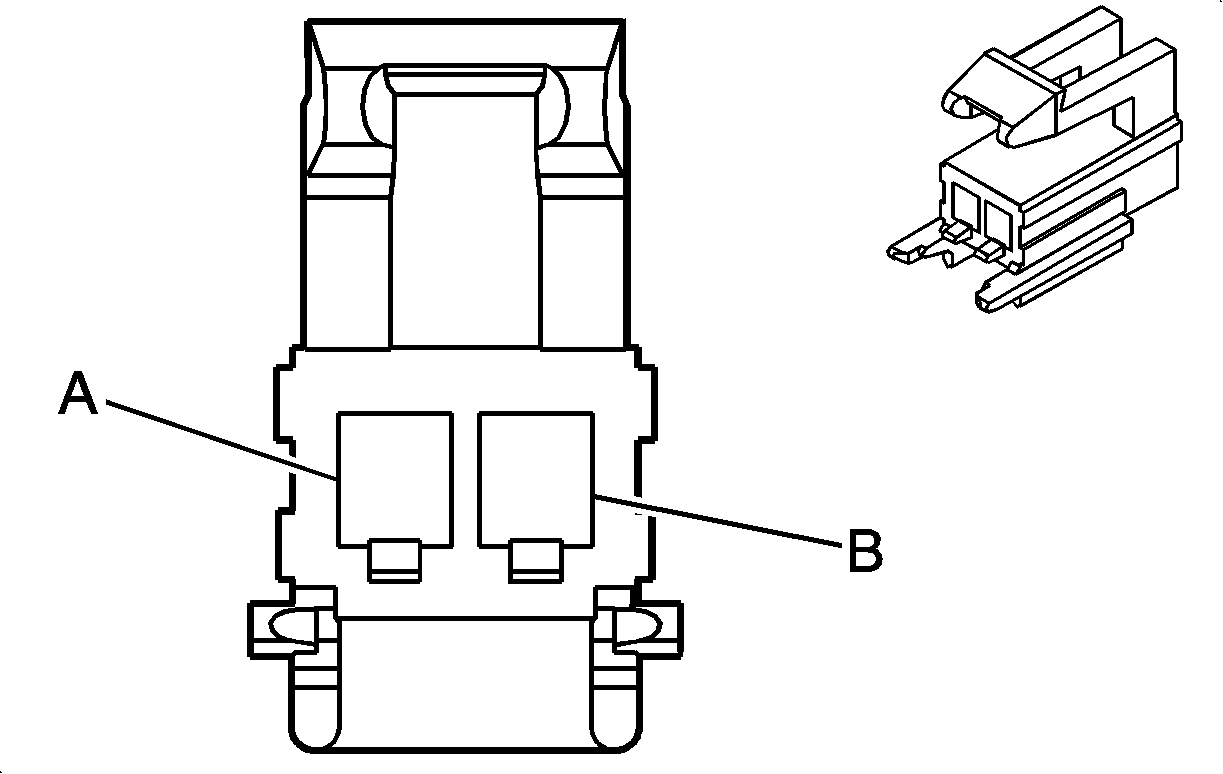
|
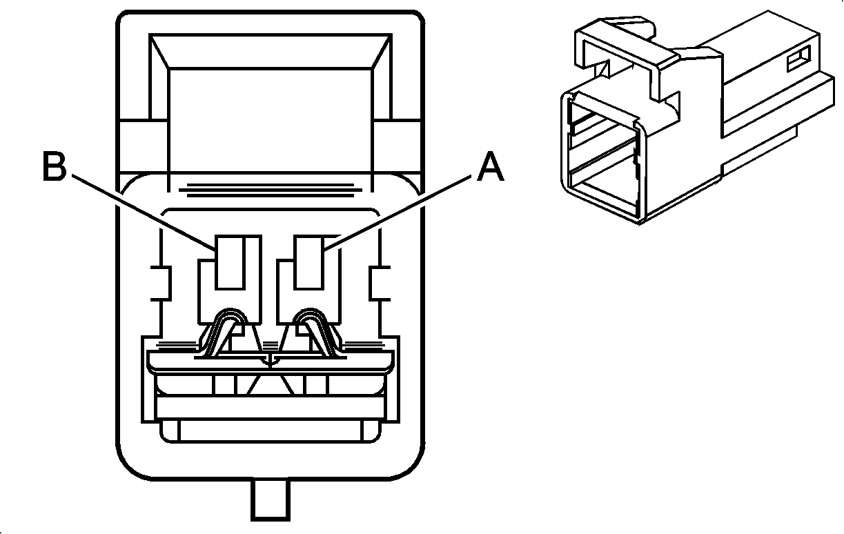
|
Connector Part Information
| Connector Part Information
|
Terminal Part Information
| Terminal Part Information
|
Pin | Wire Color | Circuit No. | Function | Pin | Wire Color | Circuit No. | Function |
|---|---|---|---|---|---|---|---|
A | PK | 5020 | Roof Rail Module - Left - Low Control | A | PK | 5020 | Roof Rail Module - Left - Low Control |
B | PU/WH | 5019 | Roof Rail Module - Left - High Control | B | PU/WH | 5019 | Roof Rail Module - Left - High Control |
C320 Body Harness to Right Roof Rail Module Harness (AYO)

|

|
Connector Part Information
| Connector Part Information
|
Terminal Part Information
| Terminal Part Information
|
Pin | Wire Color | Circuit No. | Function | Pin | Wire Color | Circuit No. | Function |
|---|---|---|---|---|---|---|---|
A | WH/BK | 5022 | Roof Rail Module- Right - Low Control | A | WH/BK | 5020 | Roof Rail Module - Left - Low Control |
B | YE/BK | 5021 | Roof Rail Module - Right - High Control | B | YE/BK | 5019 | Roof Rail Module - Left - High Control |
C321 Body Harness to the Headliner Harness (UE1)

|

|
Connector Part Information
| Connector Part Information
|
Terminal Part Information
| Terminal Part Information
|
Pin | Wire Color | Circuit No. | Function | Pin | Wire Color | Circuit No. | Function |
|---|---|---|---|---|---|---|---|
A | GY | 157 | Courtesy Lamp Control | A | GY | 157 | Courtesy Lamp Control |
B | -- | -- | Not Used | B | -- | -- | Not Used |
C | BK | 750 | Ground | C | BK | 750 | Ground |
D-E | -- | -- | Not Used | D-E | -- | -- | Not Used |
F | D-GN/WH | 2514 | Keypad Signal | F | D-GN/WH | 2514 | Keypad Signal |
G | L-GN/BK | 2515 | Keypad Supply Voltage | G | L-GN/BK | 2515 | Keypad Supply Voltage |
H | D-BU/WH | 149 | Courtesy Lamp Supply Voltage | H | D-BU/WH | 149 | Courtesy Lamp Supply Voltage |
J | D-GN | 1301 | RAP Fuse Supply Voltage | J | D-GN | 1301 | RAP Fuse Supply Voltage |
K | BN/WH | 2517 | Keypad Red LED | K | BN/WH | 2517 | Keypad Red LED |
L | -- | -- | Not Used | L | -- | -- | Not Used |
M | YE/BK | 2516 | Keypad Green LED | M | YE/BK | 2516 | Keypad Green LED |
N | GY | 655 | Cellular Telephone Microphone Signal | N | GY | 655 | Cellular Telephone Microphone Signal |
P | BARE | 1489 | Drain Wire | P | BARE | 1489 | Drain Wire |
R | L-GN | 24 | Backup Lamp Supply Voltage | R | L-GN | 24 | Backup Lamp Supply Voltage |
S | PU | 293 | Rear Defog Element Supply Voltage | S | BK | 293 | Rear Defog Element Supply Voltage |
C323 Body Harness to the Headliner Harness (w/o UE1)
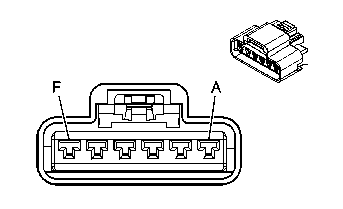
|
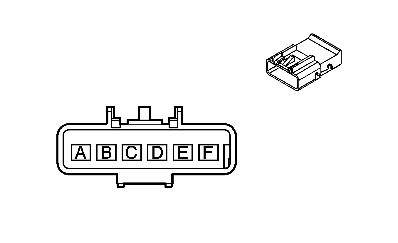
|
Connector Part Information
| Connector Part Information
|
Terminal Part Information
| Terminal Part Information
|
Pin | Wire Color | Circuit No. | Function | Pin | Wire Color | Circuit No. | Function |
|---|---|---|---|---|---|---|---|
A | PU | 293 | Rear Defog Element Supply Voltage | A | PU | 293 | Rear Defog Element Supply Voltage |
B | GY | 157 | Interior Lamp Control | B | GY | 157 | Interior Lamp Control |
C | BK | 750 | Ground | C | BK | 750 | Ground |
D | D-BU/WH | 149 | Courtesy Lamp Supply Voltage | D | D-BU/WH | 149 | Courtesy Lamp Supply Voltage |
E | D-GN | 1301 | Retained Accessory Power Fuse Supply Voltage | E | D-GN | 1301 | Retained Accessory Power Fuse Supply Voltage |
F | -- | -- | Not Used | F | -- | -- | Not Used |
C400 Battery Cable to the Body Harness
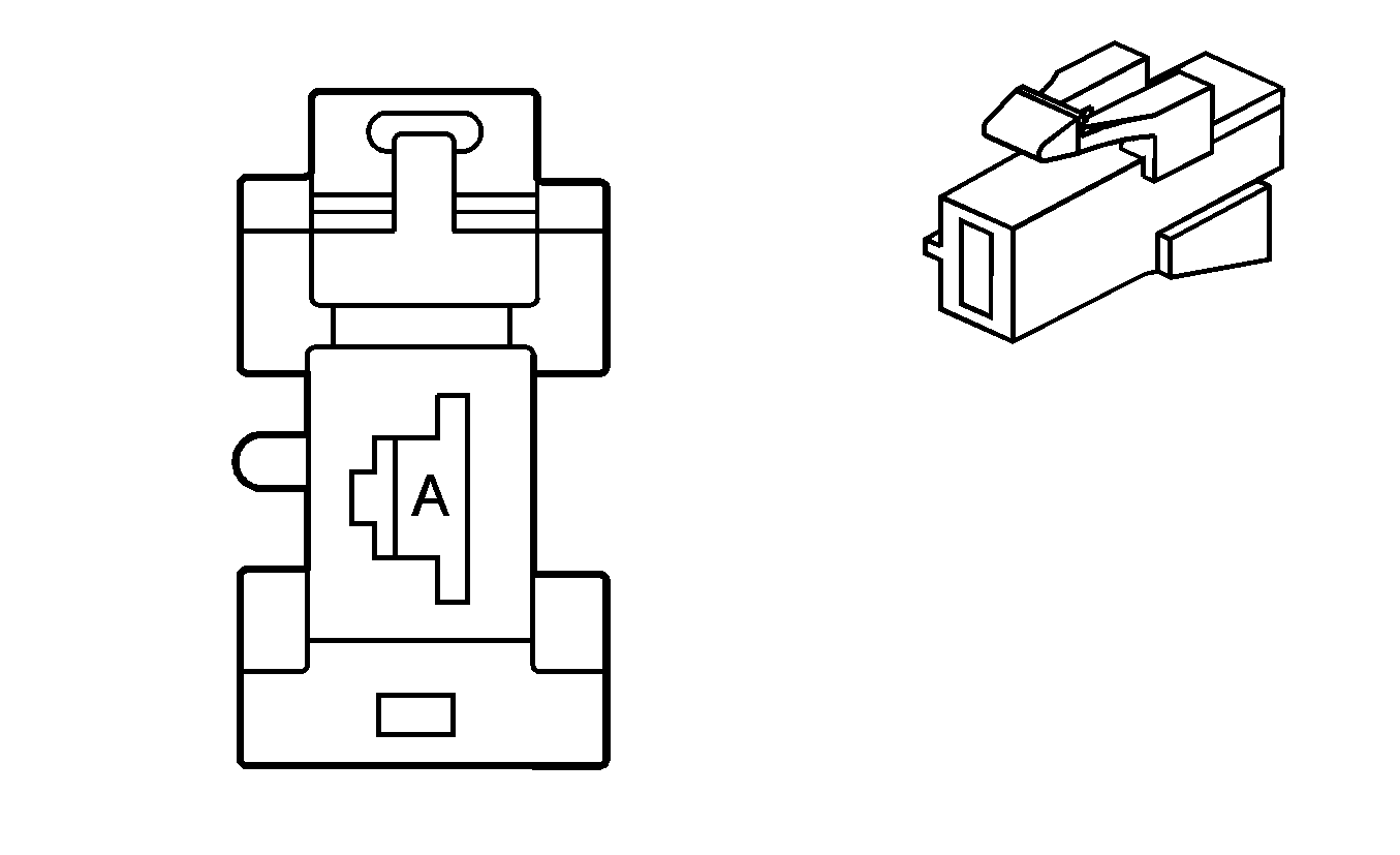
|
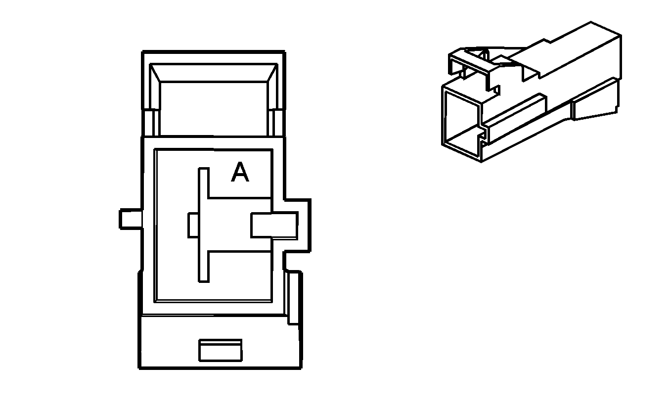
|
Connector Part Information
| Connector Part Information
|
Terminal Part Information
| Terminal Part Information
|
Pin | Wire Color | Circuit No. | Function | Pin | Wire Color | Circuit No. | Function |
|---|---|---|---|---|---|---|---|
A | RD | 1 | Battery Positive Voltage | A | RD | 1 | Battery Positive Voltage |
C401 Body Harness to the Rear Compartment Lid Harness
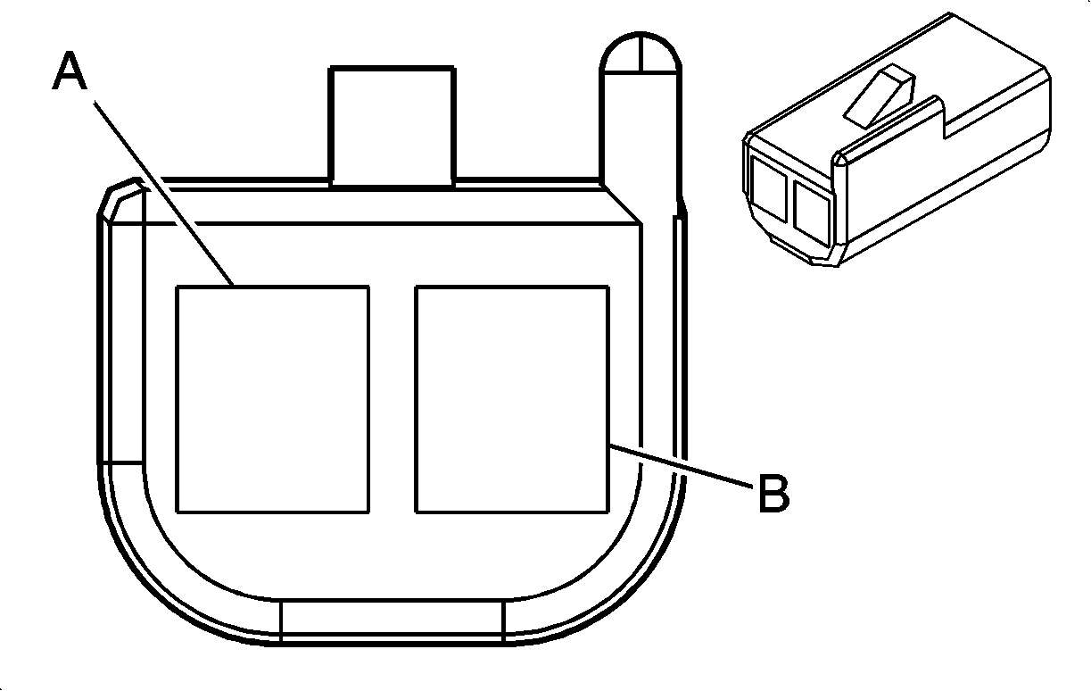
|
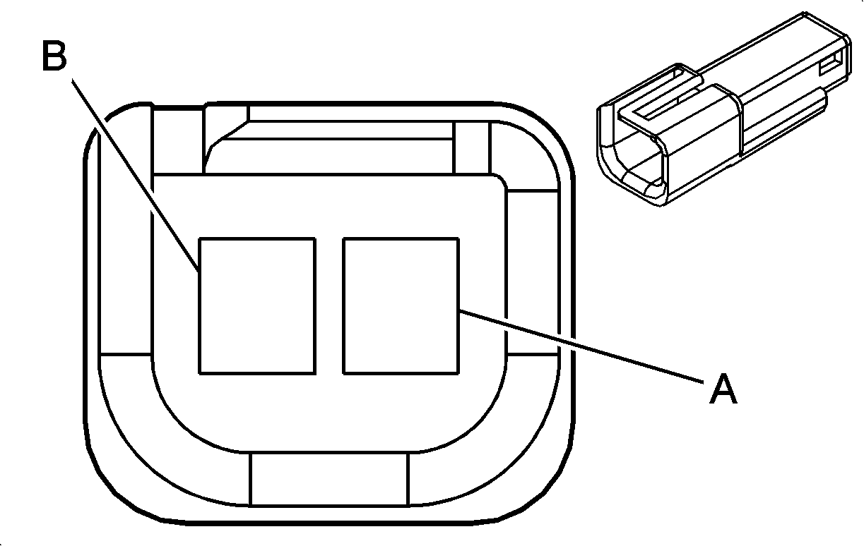
|
Connector Part Information
| Connector Part Information
|
Terminal Part Information
| Terminal Part Information
|
Pin | Wire Color | Circuit No. | Function | Pin | Wire Color | Circuit No. | Function |
|---|---|---|---|---|---|---|---|
A | BK | 750 | Ground | A | BK | 750 | Ground |
B | OG/BK | 737 | Rear Compartment Lamp Control | B | OG/BK | 737 | Rear Compartment Lamp Control |
C402 Body Harness to the Rear Compartment

|

|
Connector Part Information
| Connector Part Information
|
Terminal Part Information
| Terminal Part Information
|
Pin | Wire Color | Circuit No. | Function | Pin | Wire Color | Circuit No. | Function |
|---|---|---|---|---|---|---|---|
A | RD/BK | 142 | Battery Positive Voltage | A | RD/BK | 142 | Battery Positive Voltage |
B | RD | 1 | Battery Positive Voltage | B | RD | 1 | Battery Positive Voltage |
C492 Body Harness to the LR Tail Lamp Assembly Harness

|

|
Connector Part Information
| Connector Part Information
|
Terminal Part Information
| Terminal Part Information
|
Pin | Wire Color | Circuit No. | Function | Pin | Wire Color | Circuit No. | Function |
|---|---|---|---|---|---|---|---|
A | BK | 750 | Ground | A | BK | 750 | Ground |
B | YE | 18 | Left Rear Stop/Turn Lamp Supply Voltage | B | YE | 18 | Left Rear Stop/Turn Lamp Supply Voltage |
C | BN | 9 | Park Lamp Supply Voltage | C | BN | 9 | Park Lamp Supply Voltage |
D | L-GN | 24 | Backup Lamp Supply Voltage | D | L-GN | 24 | Backup Lamp Supply Voltage |
C493 Body Harness to the RR Tail Lamp Assembly Harness

|

|
Connector Part Information
| Connector Part Information
|
Terminal Part Information
| Terminal Part Information
|
Pin | Wire Color | Circuit No. | Function | Pin | Wire Color | Circuit No. | Function |
|---|---|---|---|---|---|---|---|
A | BK | 850 | Ground | A | BK | 850 | Ground |
B | D-GN | 19 | Right Rear Stop/Turn Lamp Supply Voltage | B | D-GN | 19 | Right Rear Stop/Turn Lamp Supply Voltage |
C | BN | 9 | Park Lamp Supply Voltage | C | BN | 9 | Park Lamp Supply Voltage |
D | L-GN | 24 | Backup Lamp Supply Voltage | D | L-GN | 24 | Backup Lamp Supply Voltage |
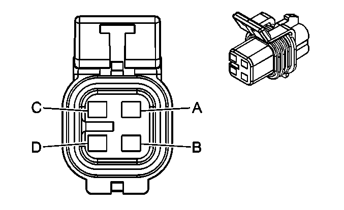
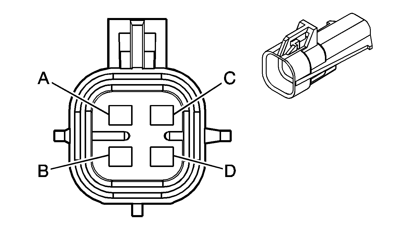
C494 Body Harness to the License Lamp Harness (Pursuit)
|
|
Connector Part Information
| Connector Part Information
|
Terminal Part Information
| Terminal Part Information
|
Pin | Wire Color | Circuit No. | Function | Pin | Wire Color | Circuit No. | Function |
|---|---|---|---|---|---|---|---|
A | L-GN | 24 | Backup Lamp Supply Voltage | A | BN | 9 | Backup Lamp Supply Voltage |
B | BN | 9 | Park Lamp Supply Voltage | B | BN | 24 | Park Lamp Supply Voltage |
C | BK | 750 | Ground | C | BK | 750 | Ground |
D | -- | -- | Not Used | D | -- | -- | Not Used |
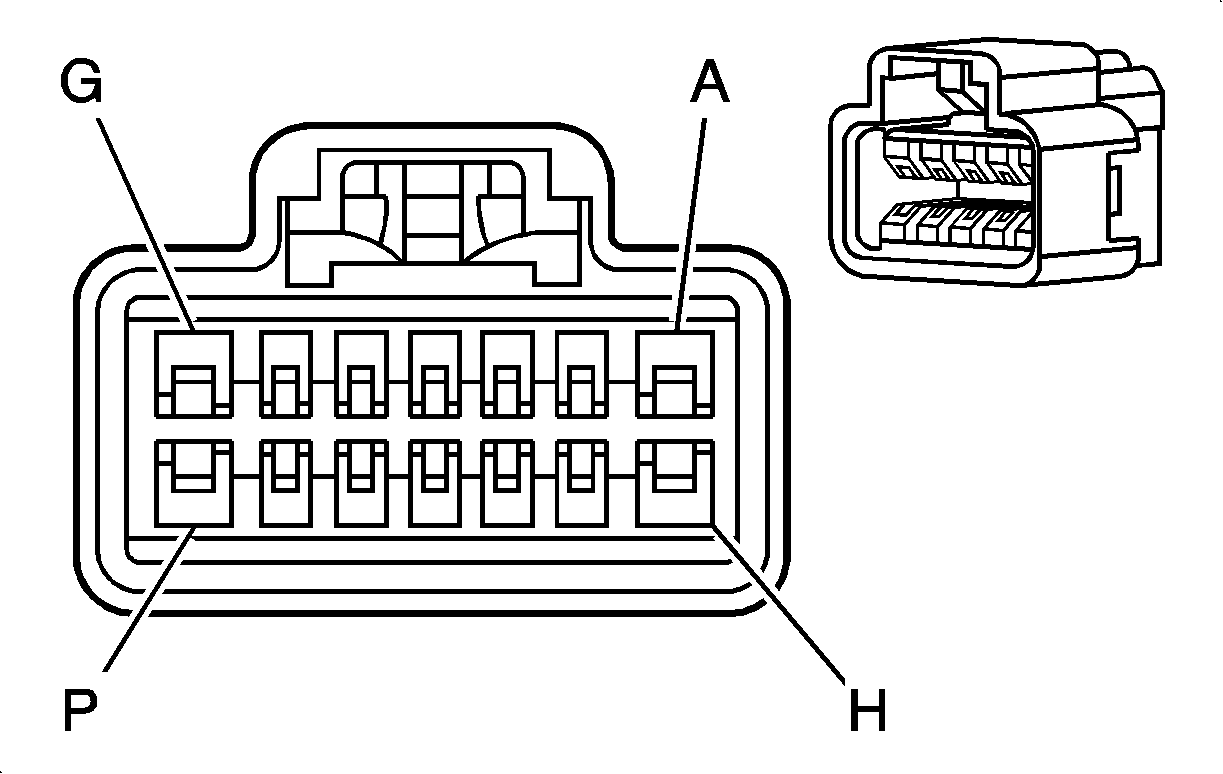
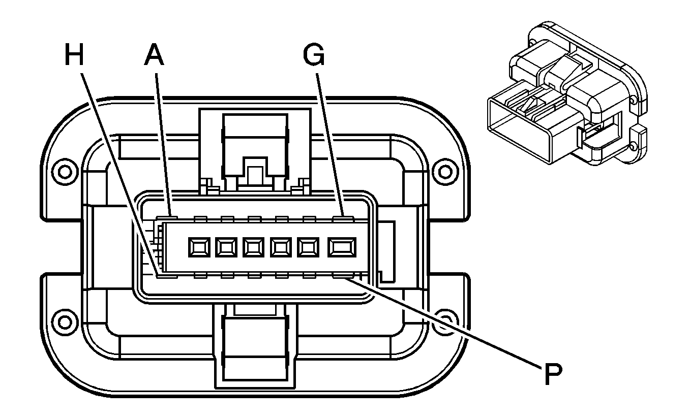
C700 Body Harness to the LR Door Harness (Sedan)
|
|
Connector Part Information
| Connector Part Information
|
Terminal Part Information
| Terminal Part Information
|
Pin | Wire Color | Circuit No. | Function | Pin | Wire Color | Circuit No. | Function |
|---|---|---|---|---|---|---|---|
A | D-BU | 1307 | Power Window Master Switch Lockout Signal | A | D-BU/WH | 1307 | Power Window Master Switch Lockout Signal |
B | TN | 294 | Door Lock Actuator Unlock Control | B | TN | 294 | Door Lock Actuator Unlock Control |
C | GY | 295 | Door Lock Actuator Lock Control | C | GY | 295 | Door Lock Actuator Lock Control |
D-F | -- | -- | Not Used | D-F | -- | -- | Not Used |
G | D-GN | 168 | Power Window Master Switch Left Rear Up Signal | G | D-GN | 168 | Power Window Master Switch Left Rear Up Signal |
H | PU | 169 | Power Window Master Switch Left Rear Down Signal | H | PU | 169 | Power Window Master Switch Left Rear Down Signal |
J-P | -- | -- | Not Used | J-P | -- | -- | Not Used |
C800 Body Harness to the RR Door Harness (Sedan)

|

|
Connector Part Information
| Connector Part Information
|
Terminal Part Information
| Terminal Part Information
|
Pin | Wire Color | Circuit No. | Function | Pin | Wire Color | Circuit No. | Function |
|---|---|---|---|---|---|---|---|
A | D-BU | 1307 | Power Window Master Switch Lockout Signal (AU3) | A | D-BU/WH | 1307 | Power Window Master Switch Lockout Signal (AU3) |
B | TN | 294 | Door Lock Actuator Unlock Control (AU3) | B | TN | 294 | Door Lock Actuator Unlock Control (AU3) |
C | GY | 295 | Door Lock Actuator Lock Control (AU3) | C | GY | 295 | Door Lock Actuator Lock Control (AU3) |
D-F | -- | -- | Not Used | D-F | -- | -- | Not Used |
G | L-GN | 170 | Power Window Master Switch Right Rear Up Signal (AU3) | G | L-GN | 170 | Power Window Master Switch Right Rear Up Signal (AU3) |
H | PU | 171 | Power Window Master Switch Right Rear Down Signal (AU3) | H | PU | 171 | Power Window Master Switch Right Rear Down Signal (AU3) |
J-P | -- | -- | Not Used | J-P | -- | -- | Not Used |
