By design, all air flow through the heater A/C module must pass through the evaporator. Thus, the system discharge air temperature is regulated by varying the amount of ambient non-RECIRC or in-vehicle RECIRC mode air that passes through the heater core. A vacuum regulates the control of air through the system. Various positions on the control assembly cause the mode valves to mix and direct the following types of air through the air ducts.
| • | Cooled air |
| • | Heated air |
| • | Outside air |
Air flows through the HVAC system as described for each of the following modes:
OFF: Only forced air flows from the heater system.MAX:
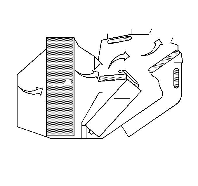
Recirculated air flows through the instrument panel outlets.
BI-LEVEL:
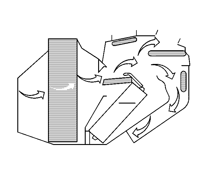
Outside air flows through the IP outlets and the floor outlets.
VENT: Outside air flows through the instrument panel outlets. The compressor does not operate.
HEATER: Most of the air flows through the floor outlets. A small amount of air flows through the defroster duct.
MIX/BLEND:
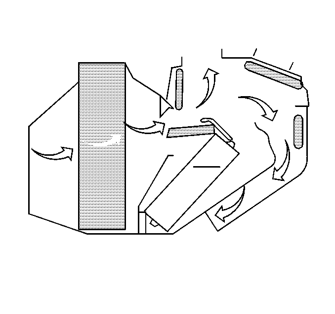
Equal amounts of air flow from the floor vents and the defrost.
LOWER:
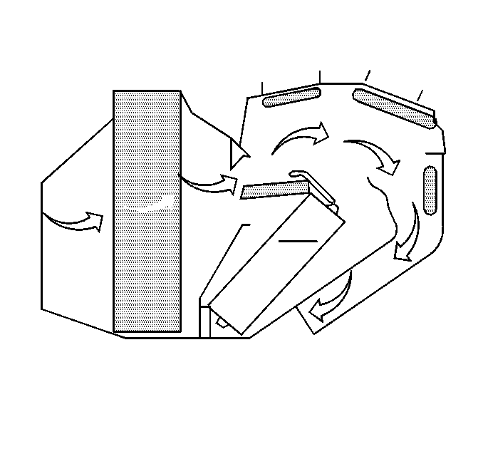
Outside air is directed to the floor vents.
RECIRC: Inlet air to the heater A/C module is drawn from the vehicle's interior rather than from outside of the vehicle. This mode is used for maximum air cooling/dehumidification.
DEFROST:
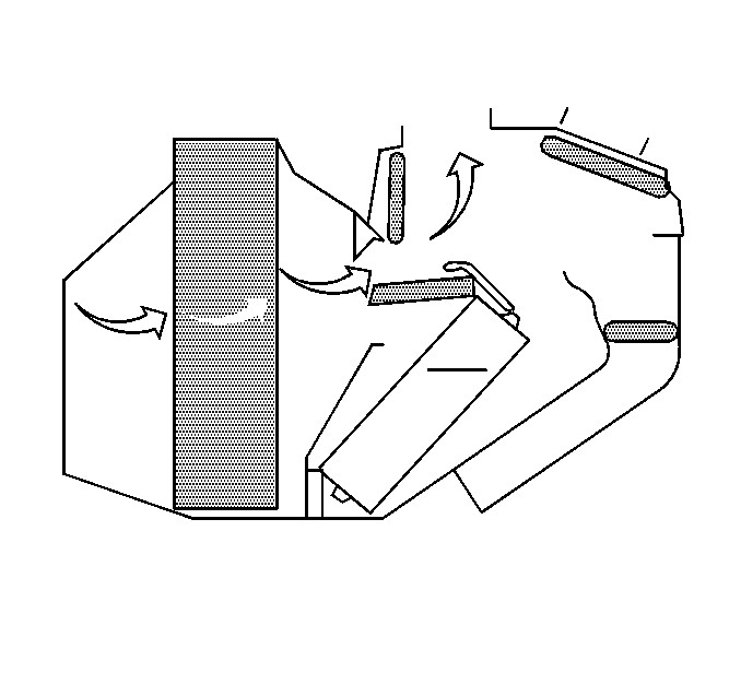
Air flows from the defroster outlets. A small amount of air flows from the floor outlets.
The PCM controls the operation of the cooling fan through the cooling fan relay. Complete wiring diagrams and diagnosis for the A/C electrical system is in the HVAC Controls in Electrical Diagnosis. This section also contains additional diagnostic information regarding air flows and vacuum logic.
Vacuum Lines
Vacuum lines are molded to a connector which is attached to a main vacuum line from the engine compartment. Replace the entire harness if one of the following conditions exists:
| • | Hose leakage |
| • | Hose collapse |
Replace the harness by performing the following steps:
- Cut the hose.
- Insert a plastic connector.
Vacuum Tank
During heavy acceleration, the vacuum supply drops. A check valve in the vacuum line maintains vacuum in the vacuum tank. This allows the vacuum to be available for use under load conditions.
Ducts and Outlets
A system of ducts and outlets direct air to the passenger compartment.
Obstructions in the ducts and outlets may cause poor air output. Inspect the following air passages for obstructions such as leaves, dirt or other objects:
| • | The defroster duct |
| • | The heater duct |
| • | The A/C ducts |
| • | The vent ducts |
A/C systems also come equipped with side window defoggers.
Removal and installation of all ductwork is covered under On-Vehicle service.
Ventilation
The air distribution system provides fresh air ventilation for the passenger compartment in all operating modes. Even in the OFF mode, the forward movement of the vehicle forces fresh outside air into the air distribution system.
After the air is warmed or cooled to the desired temperature, the air is discharged from the outlets appropriate to the selected operating mode. When all of the windows are closed, the addition of outside air builds a slight positive pressure within the passenger compartment. The pressure forces stale air to leave the vehicle through a pressure relief valve.
