For 1990-2009 cars only
Removal Procedure
- Install the engine support fixture. Refer to Engine Support Fixture in Engine Mechanical
- Raise and support the vehicle. Refer to Lifting and Jacking the Vehicle in General Information.
- Remove the stabilizer shaft. Refer to Stabilizer Shaft Replacement in Front Suspension.
- Remove the power steering gear heat shield. Refer to Steering Gear Heat Shield Replacement in Power Steering System.
- Remove the power steering gear from the frame. Refer to Steering Gear Replacement in Power Steering System.
- Use a strap in order to secure the power steering gear to the exhaust manifold.
- Remove the power steering cooler line clamps from the frame. Refer to Power Steering Cooler Pipe/Hose Replacement in Power Steering System.
- Use wire in order to secure the power steering cooler line to an engine component.
- Remove the engine mount nuts. Refer to Engine Mount Replacement in Engine Mechanical.
- Remove the transaxle mount nuts. Refer to Transmission Mount Replacement .
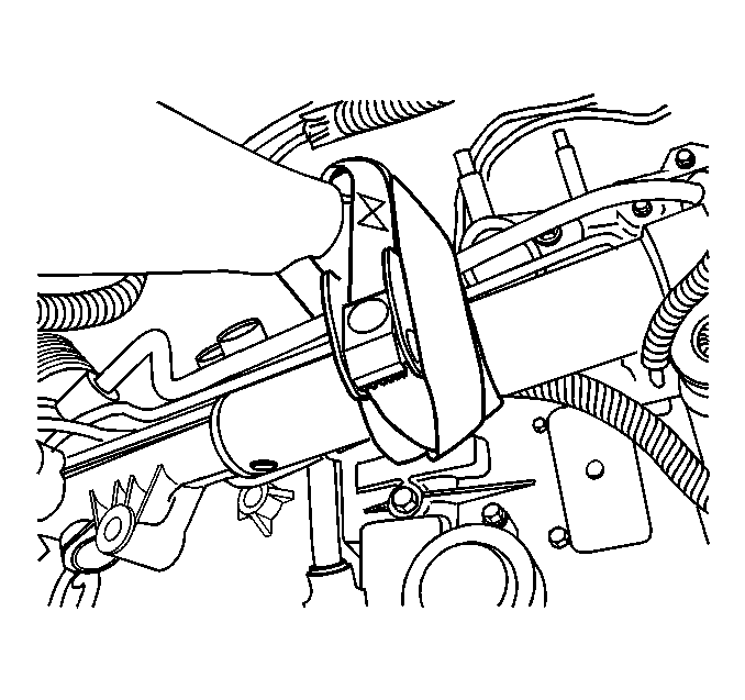
- Use a utility stand in order to support the frame front.
- Use a utility stand in order to support the frame rear.
- Remove the frame bolts.
- Use the utility stand in order to lower the frame rear for access to the forward servo cover.
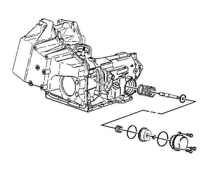
- Position a drain pan under the forward servo cover.
- Remove the forward band servo cover bolts.
- Remove the forward servo cover.
- Remove the forward servo cover O-ring.
- Remove the servo piston assembly.
- Remove the servo spring.


Installation Procedure
- Install the servo spring.
- Install the servo piston assembly.
- Install the forward servo cover O-ring.
- Install the forward servo cover.
- Install the forward band servo cover bolts.
- Remove the drain pan from under the forward servo cover.
- Use the utility stand in order to raise the frame rear.
- Install the NEW frame bolts.
- Adjust the utility straps as necessary in order to align the powertrain mounts with the frame.
- Install the transaxle mount nuts. Refer to Transmission Mount Replacement .
- Install the engine mount nuts. Refer to Engine Mount Replacement in Engine Mechanical
- Install the power steering gear to the frame. Refer to Steering Gear Replacement in Power Steering System.
- Install the power steering gear heat shield. Refer to Steering Gear Heat Shield Replacement in Power Steering System.
- Install the stabilizer shaft. Refer to Stabilizer Shaft Replacement in Front Suspension.
- Lower the vehicle.
- Remove the engine support fixture. Refer to Engine Support Fixture in Engine Mechanical.
- Reset the TAP values. Refer to Adapt Function .

Notice: Refer to Fastener Notice in the Preface section.
Tighten
Tighten the forward band servo cover bolts to 12 N·m (106 lb in).
Important: Ensure that the power steering cooler line does not become trapped or damaged during this step.
Important: It is recommended that transmission adaptive pressure (TAP) information be reset.
Resetting the TAP values using a scan tool will erase all learned values in all cells. As a result, The ECM, PCM or TCM will need to relearn TAP values. Transmission performance may be affected as new TAP values are learned.