Generator Overhaul A-Type : Mando
Disassembly Procedure
- Remove the generator. Refer to Generator Replacement .
- Remove the front bracket and rear bracket.
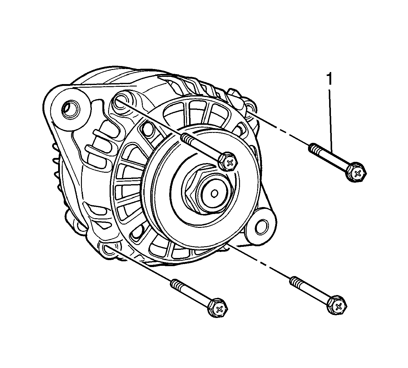
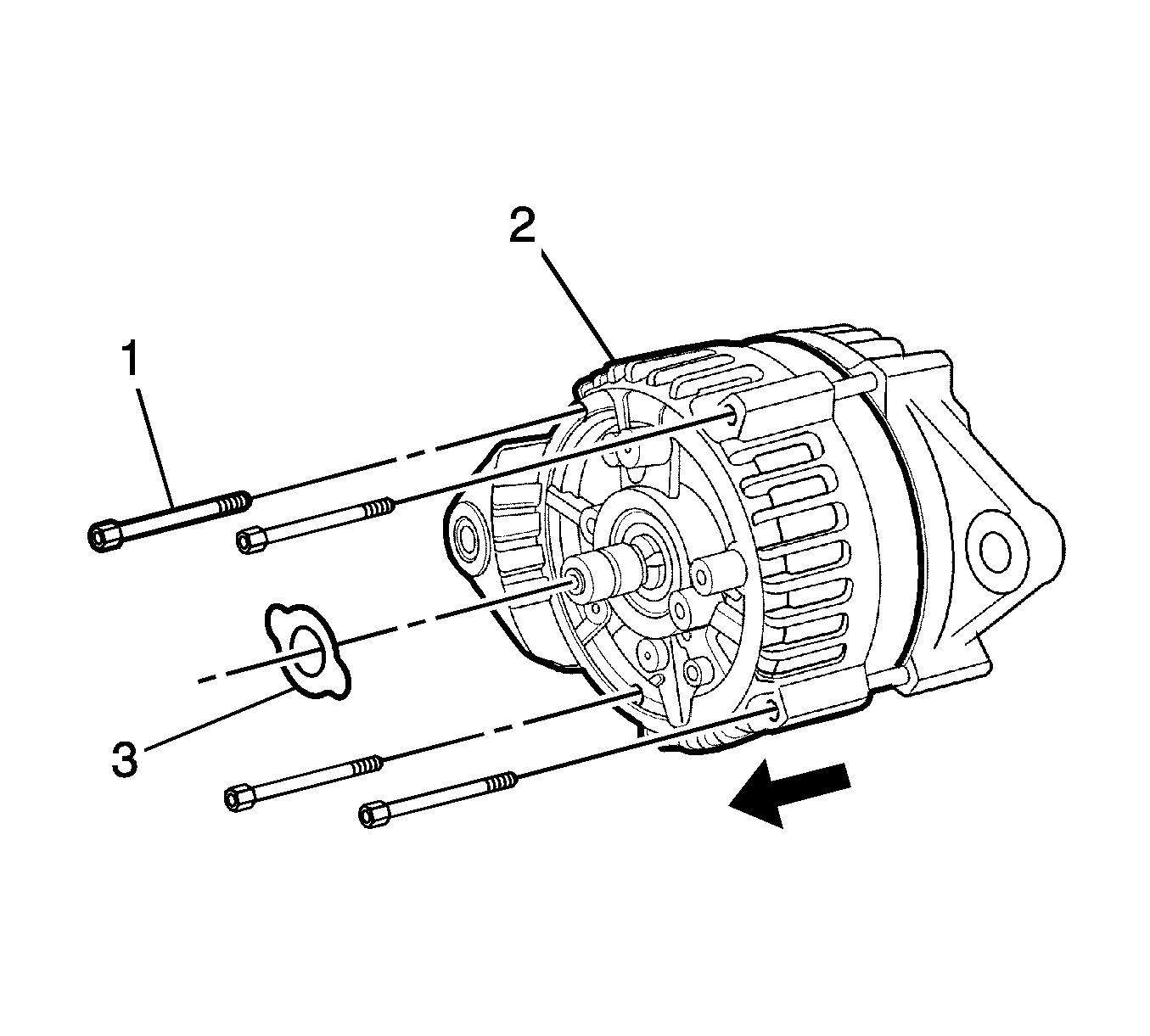
- Remove the through-bolts (1).
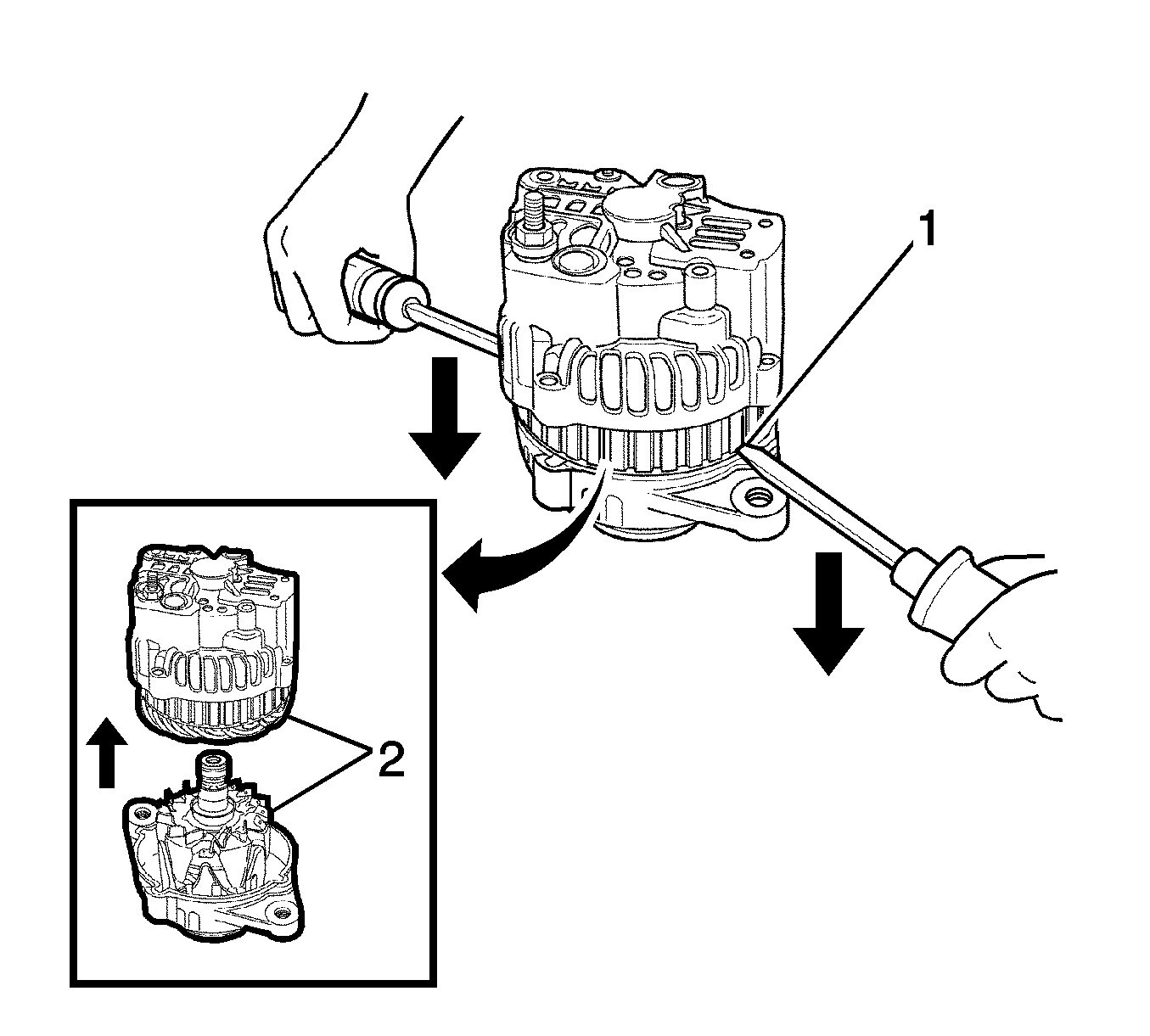
- Pry front bracket downwards using a screwdriver (1).
- Separate the front bracket and rear bracket (2).
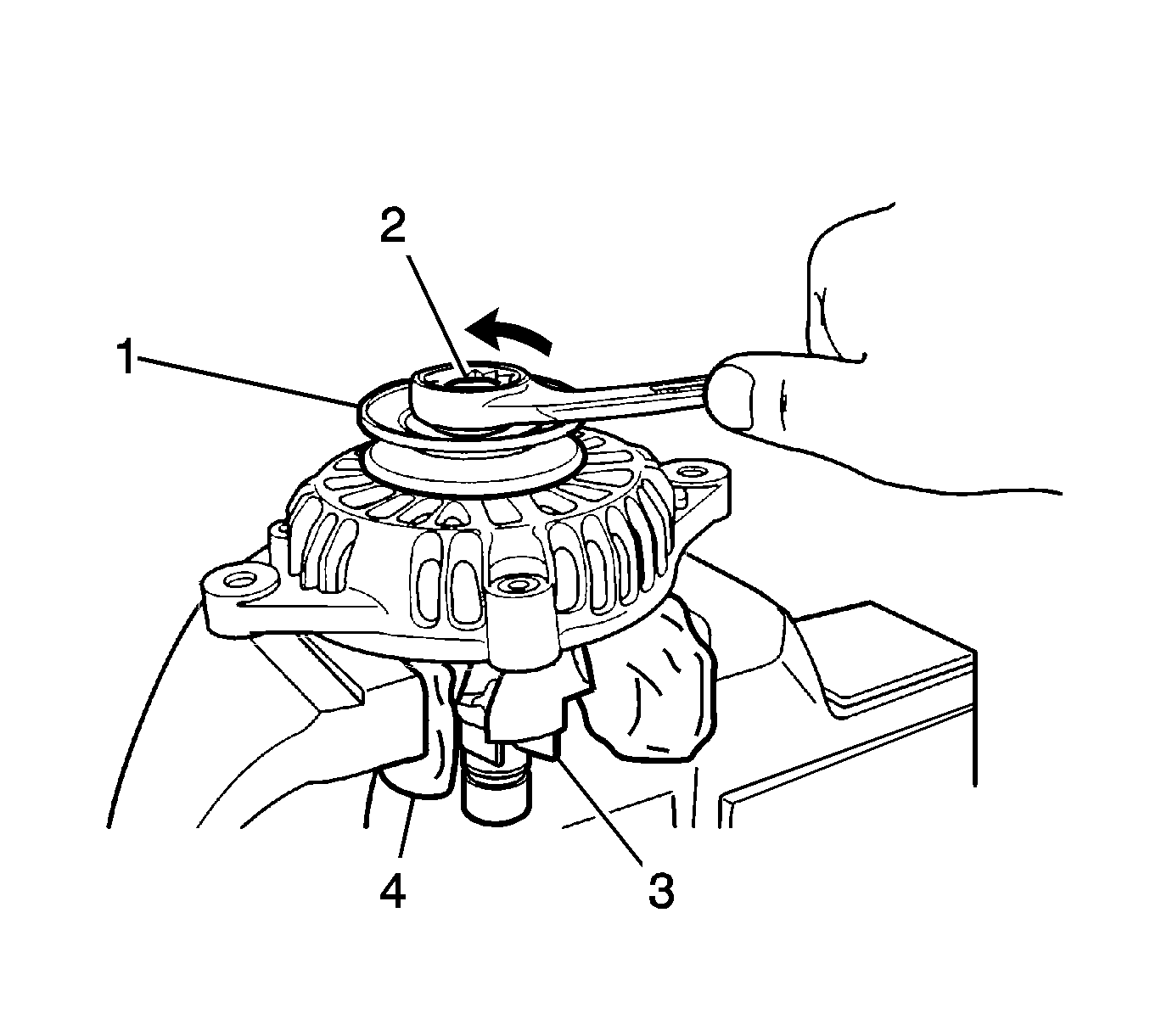
- Cover the rotor assembly with the cloth (4).
- Place the pulley upward and vice the rotor (3).
- Remove the pulley nut (2).
- Remove the pulley (1).
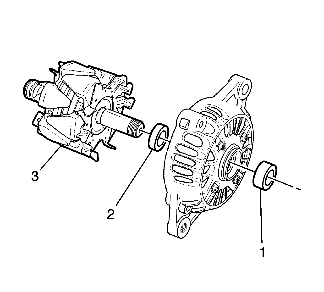
- Remove the large collar (1).
- Remove the rotor from the front bracket (3).
- Remove the small collar from the rotor shaft (2).
- Remove the support plate screws (1).
- Remove the plate (3).
- Remove the front bearing using the press (2).
- Remove the battery positive terminal nut (1) from the rear bracket.
- Remove the washer (2).
- Remove the rectifier screw (3).
- Remove the brush holder and regulator assembly screws (1).
- Remove the stator assembly from the rear bracket with the rectifier/brush holder/regulator (2).
- Remove the rectifier/brush holder/regulator connections (2).
- Remove the stator and rectifier connections (1).
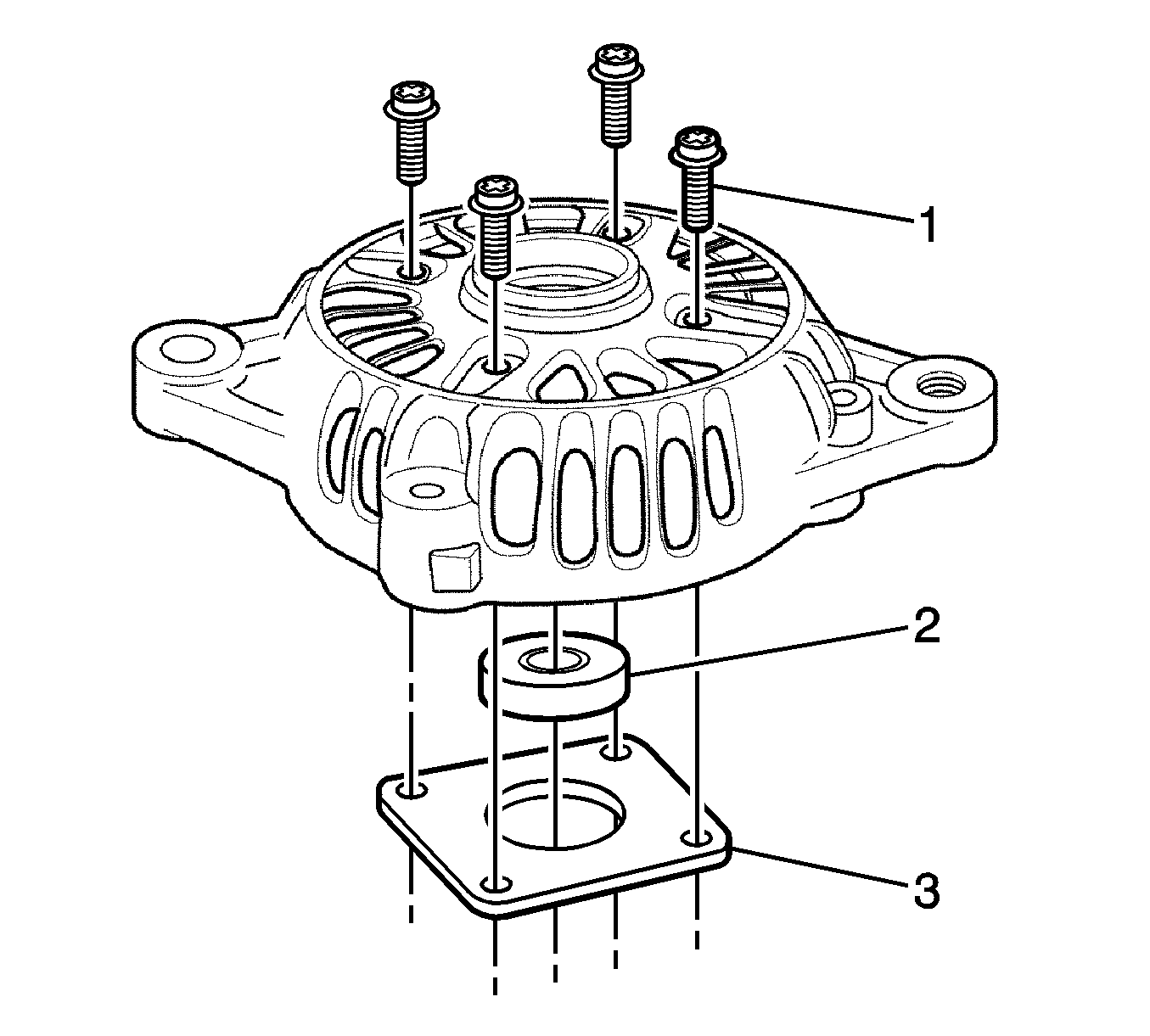
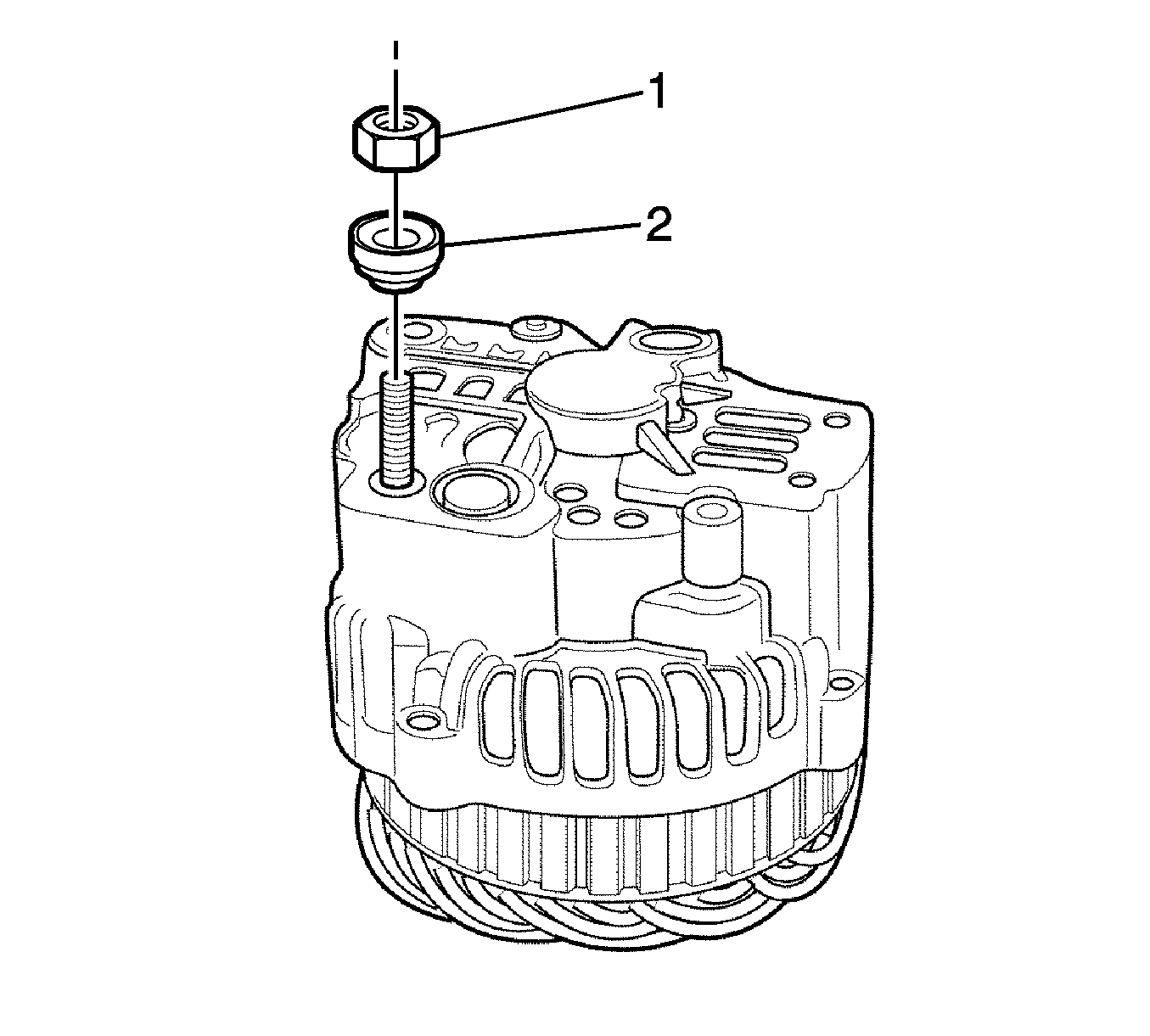
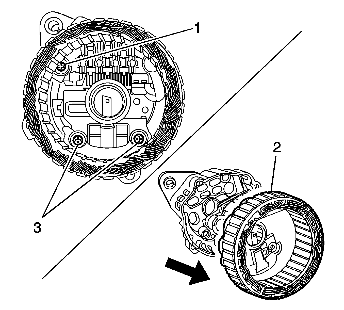
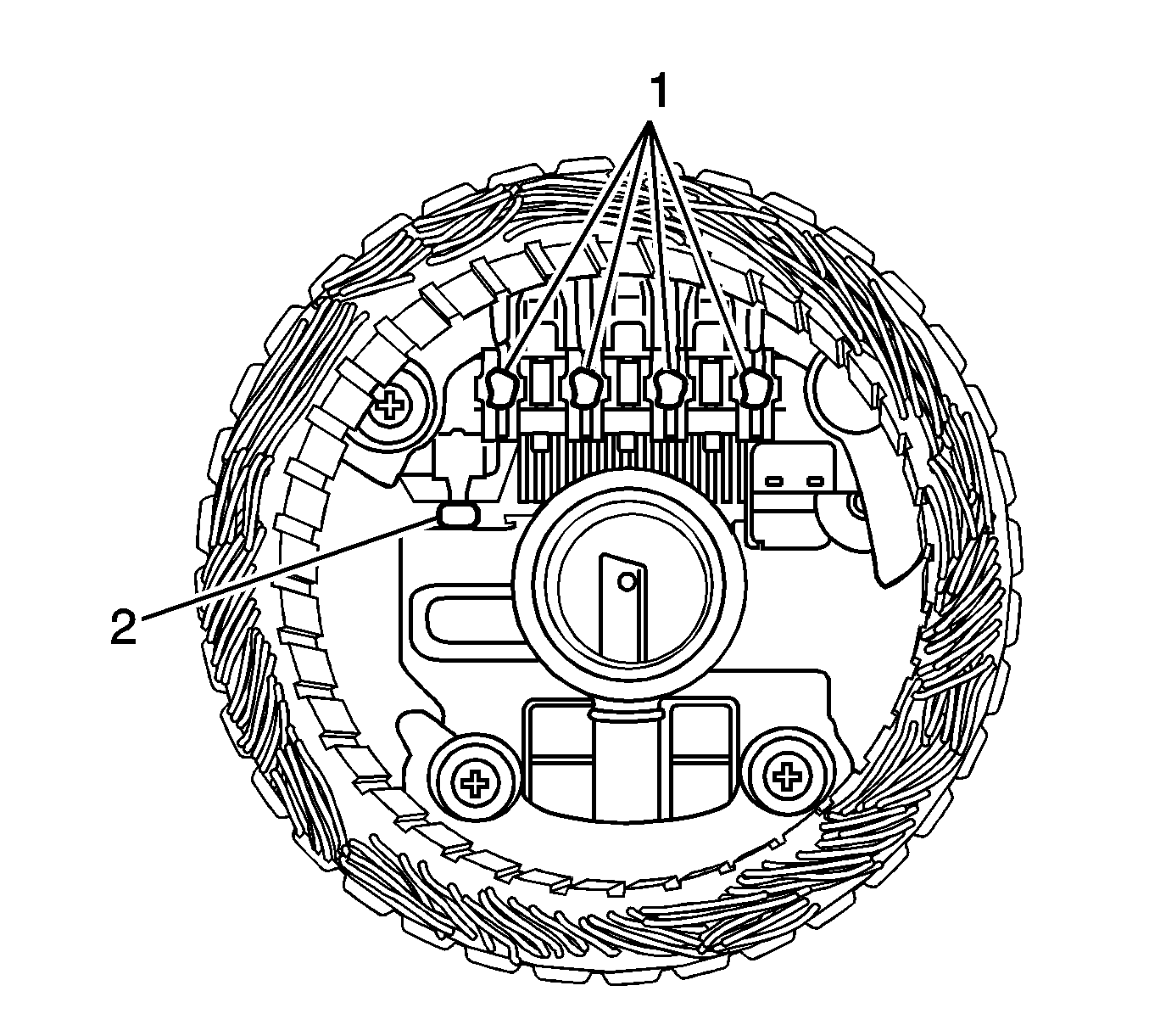
Notice: If the stator connections are welded in, use just enough heat to melt the lead. Avoid using to much heat as it can damage the diodes.
Assembly Procedure
- Assemble the stator assembly into the rear bracket and rotor assembly (1).
- Install the brush holder/regulator/rectifier screws (1).
- Install the battery positive terminal nut (2).
- Install the front bearing spot plate screws (1).
- Install the generator pulley nut (1).
- Install the through-bolts (2).
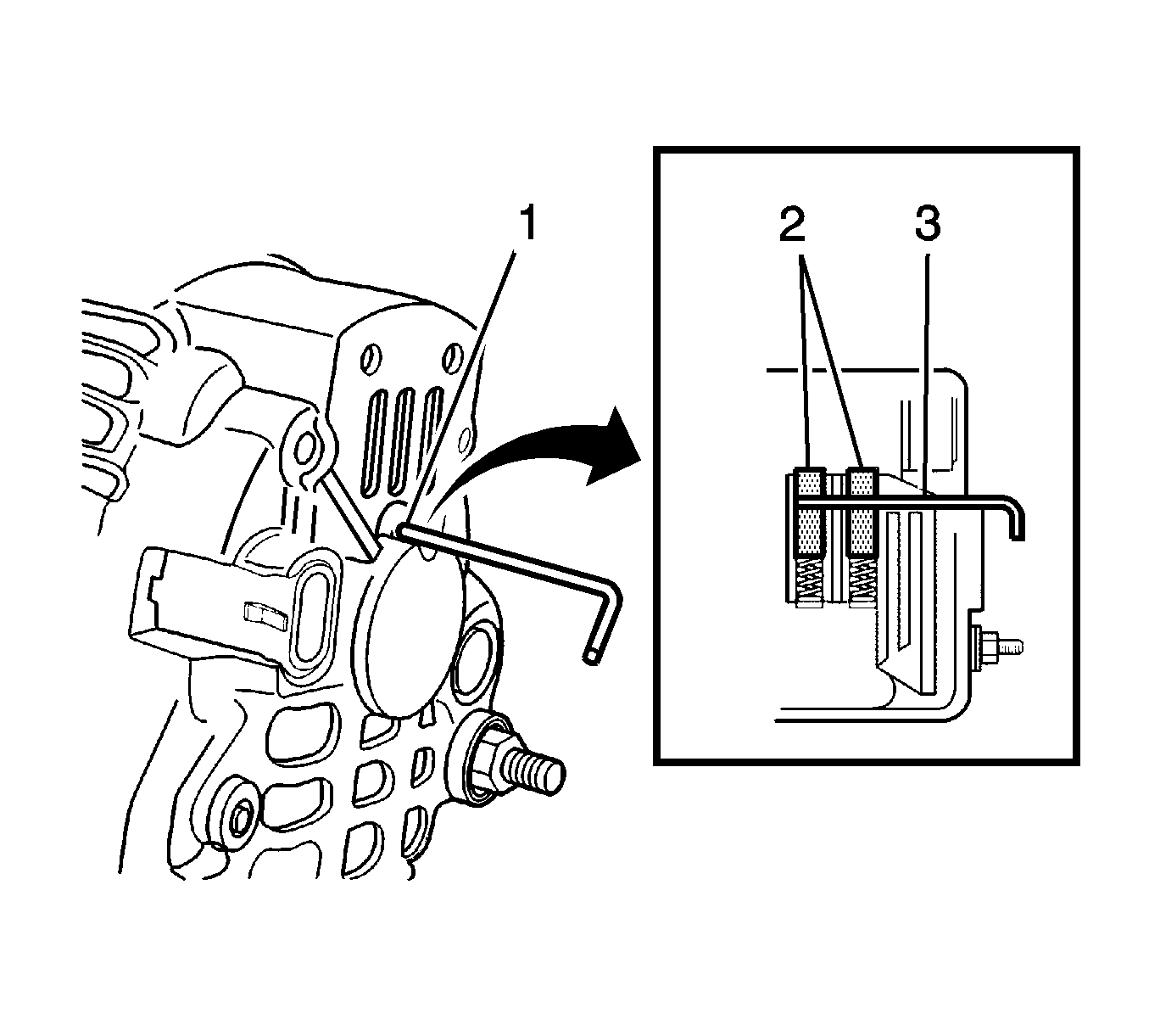
| • | Brushes (2) |
| • | Hole (3) |
Notice: Refer to Fastener Notice in the Preface section.
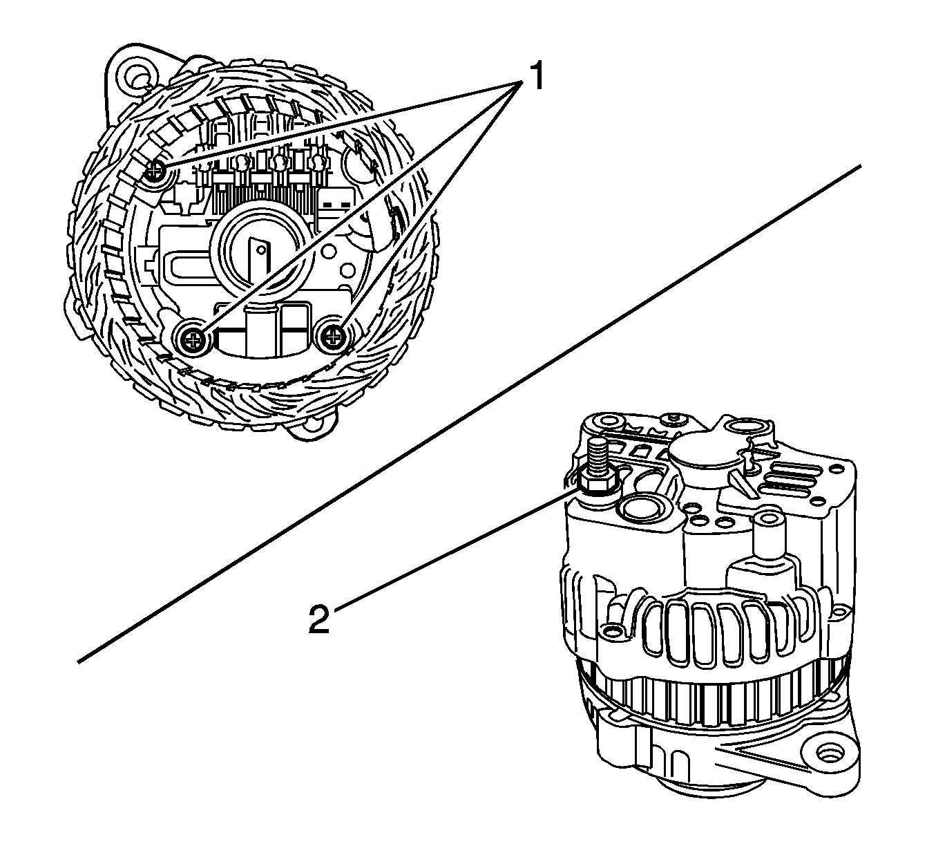
Tighten
Tighten the brush holder/regulator/rectifier screws to 9-12 N·m (80-106 lb in).
Tighten
Tighten the battery positive terminal nut to 4-7 N·m (35-62 lb in).
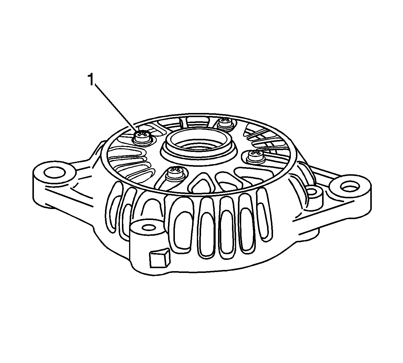
Tighten
Tighten the front bearing spot plate screws to 6-8 N·m (53-71 lb in).
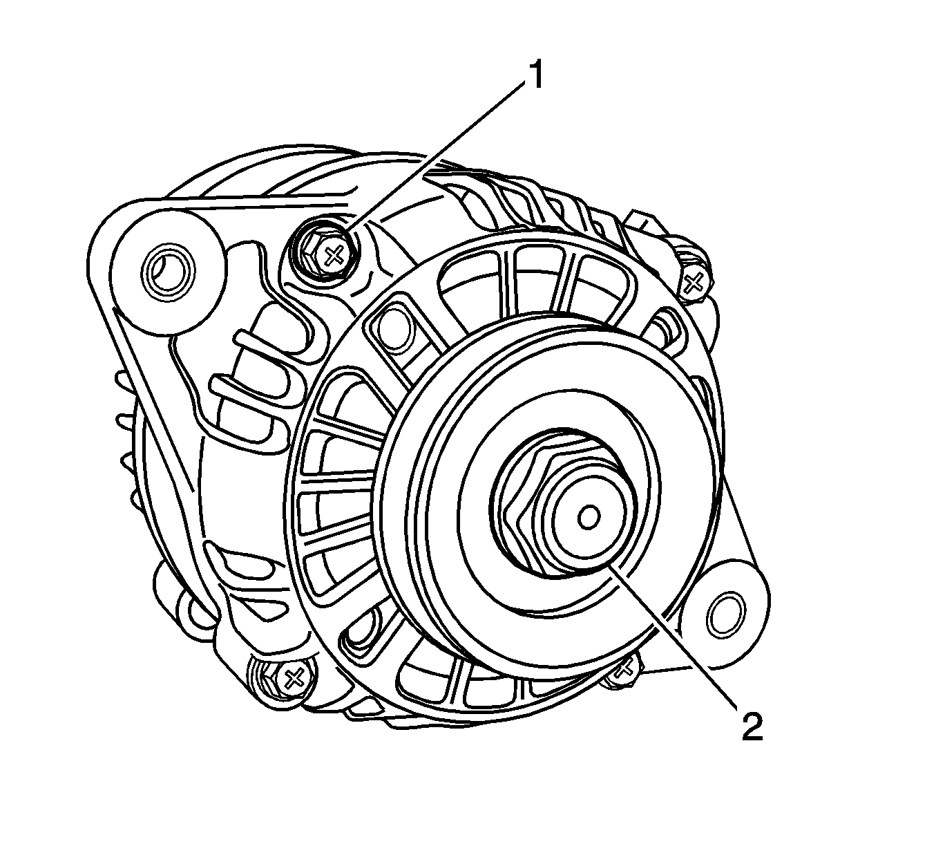
Tighten
Tighten the generator pulley nut to 80-110 N·m (59-81 lb ft).
Tighten
Tighten the through-bolts to 4-6 N·m (35-53 lb in).
Generator Overhaul B-Type : DAC
Disassembly Procedure
- Remove the generator. Refer to Generator Replacement .
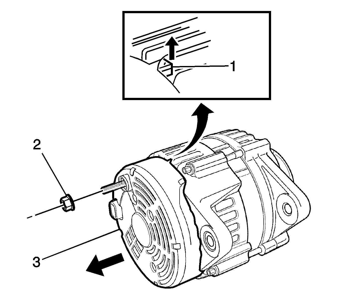
- Remove the battery positive terminal nut (2).
- Remove the cover (3) and cover latch (1).
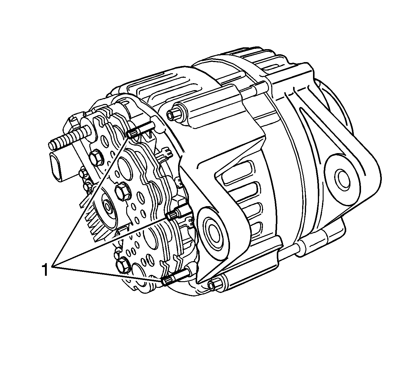
- Remove the stator coil lead and rectifier diode lead connections (1).
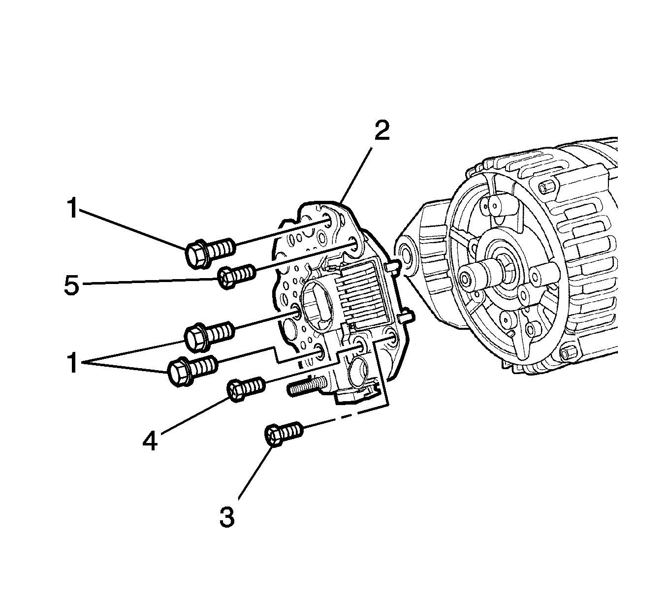
- Remove the rectifier bolts (1).
- Remove the rectifier/regulator screw (2).
- Remove the brush holder/regulator screw (3).
- Remove the regulator screw (4).
- Remove the regulator/brush holder/rectifier assembly (5).
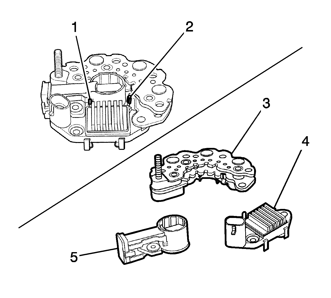
- Remove the rectifier and regulator connection (2).
- Remove the regulator and brush holder connection (1).
- Visibly inspect the rectifier (3)/regulator (4)/brush holder (5) for damage or if broken.
- Remove the shield (3).
- Remove the through-bolts (1).
- Remove the frame from the drive end bracket (2).
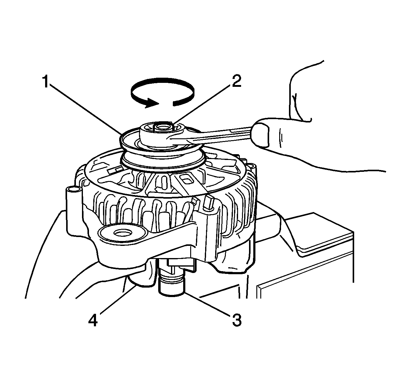
- Cover the rotor with the cloth (4).
- Place the pulley upwards and vice the rotor (3).
- Remove the pulley nut (2).
- Remove the pulley (1).
- Remove the pulley and rotor assembly from the drive end bracket.
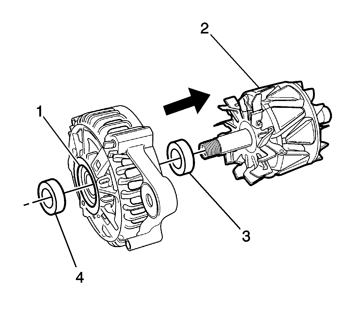
- Remove the collar (4).
- Remove the rotor from the driver end bracket (2).
- Remove the collar from the rotor shaft (3).
- Inspect the front bearing for corrosion, wear, noise, and other damage (1).
- Remove the drive end bracket, rotor, and space.
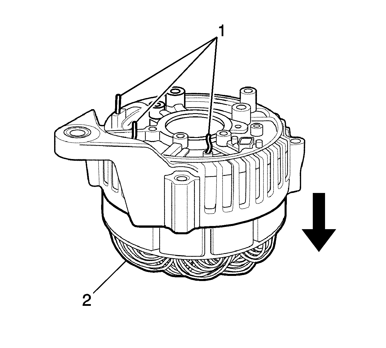
- Remove the remains (1) after the welding.
- Remove the stator assembly (2) from the frame.
Assembly Procedure
- Install the stator assembly (2) to the frame.
- Install the space, rotor and drive end bracket.
- Install the collar to the rotor shaft (3).
- Install the rotor to the driver end bracket (2).
- Install the collar (4).
- Install the pulley and rotor assembly to the drive end bracket.
- Install the pulley (1) and pulley nut (2).
- Install the frame to the driver end bracket (2).
- Install and tighten the through bolts (1).
- Install the shield (3).
- Install the regulator and brush holder connection (2).
- Install the rectifier (3) and regulator connection (2).
- Install the regulator/brush holder/rectifier assembly (5).
- Install and tighten the regulator screw (4).
- Install and tighten the brush holder/regulator screw (3).
- Install and tighten the rectifier/regulator screw (2).
- Install and tighten the rectifier bolts (1).
- Install the stator coil lead and rectifier diode lead connections (1).
- Install the cover (3) and cover latch (1).
- Install and tighten the battery positive terminal nut (2).
- Install the generator. Refer to Generator Replacement .


Notice: Refer to Fastener Notice in the Preface section.
Tighten
Tighten the pulley nut to 80-110 N·m (59-81 lb ft).


Tighten
Tighten the regulator screw to 9-12 N·m (80-108 lb in).
Tighten
Tighten the brush holder/regulator screw to 9-12 N·m (80-108 lb in).
Tighten
Tighten the rectifier/regulator screw to 9-12 N·m (80-108 lb in).
Tighten
Tighten the rectifier bolts to 9-12 N·m (80-108 lb in).


