For 1990-2009 cars only
Tools Required
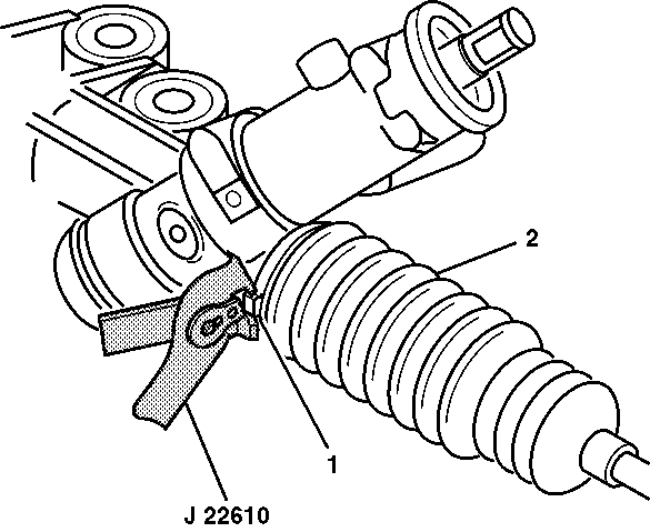
J 22610 Keystone Clamp Pliers
Removal Procedure
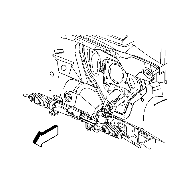
- Raise and support the vehicle. Refer to Lifting and Jacking the Vehicle .
- Remove the tire and wheel assembly. Refer to Tire and Wheel Removal and Installation .
- Remove the outer tie rod from the inner tie rod assembly. Refer to Rack and Pinion Outer Tie Rod End Replacement .
- Remove the intermediate steering shaft lower pinch bolt. Refer to Intermediate Steering Shaft Replacement .
- Remove the rear frame mounting bolts to allow for tool access. Refer to Frame Replacement .
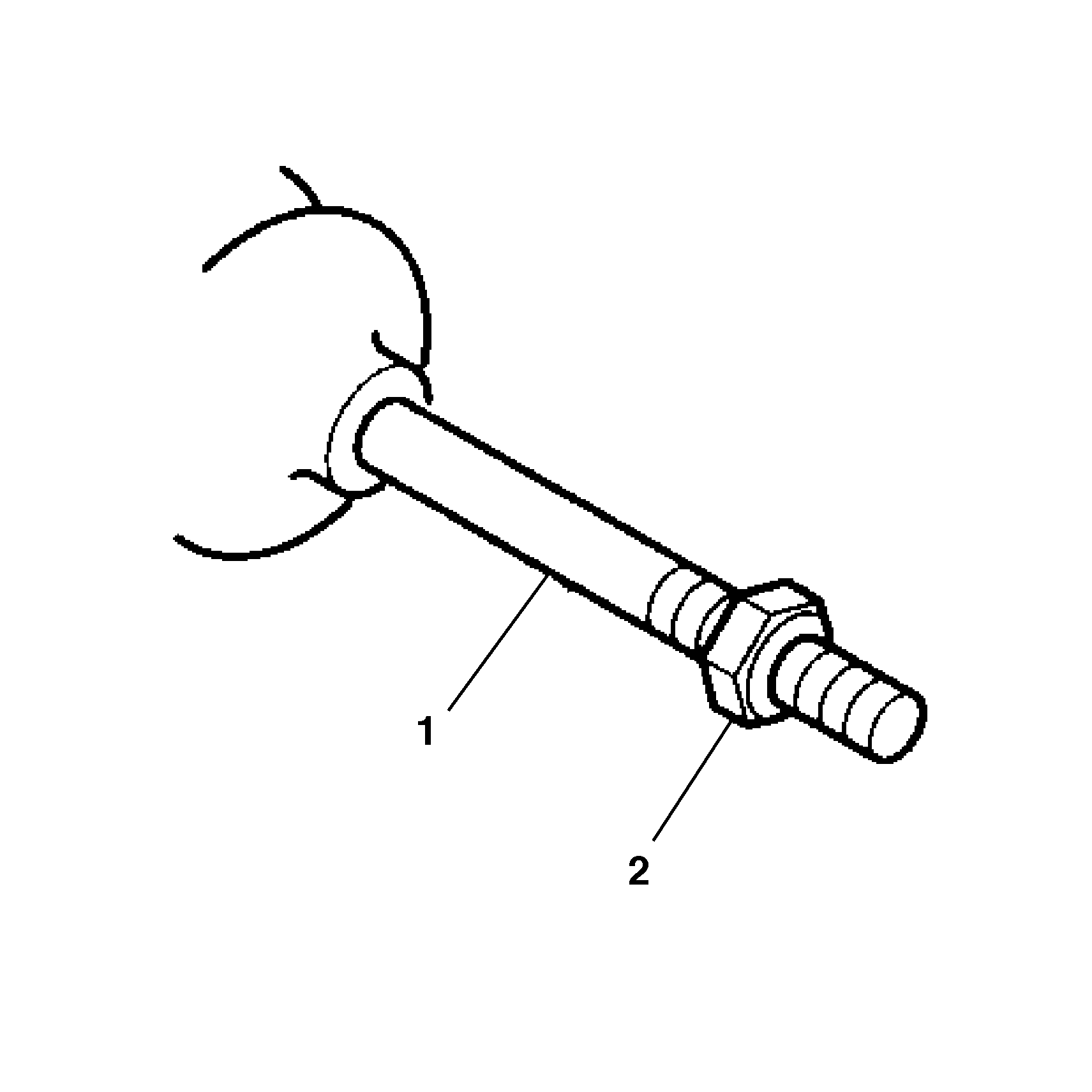
- Remove the inner tie rod jam nut (2) from the inner tie rod assembly (1).
- Remove the clamp (2) from the end of the inner tie rod boot (1).
- Remove the inner tie rod boot clamp (1) from the inner tie rod boot (3) with side cutters.
- Discard the inner tie rod boot clamp (1).
- Remove the inner tie rod boot (3) and the breather tube (2).


Important:
• Prior to removing breather tube (2) or the inner tie rod boot (3), mark the location of the breather tube (2) on the power steering gear assembly. • After removing the boot, inspect the inner tie rod for evidence of corrosion or contamination. If none is evident, continue with the repair. If corrosion or contamination is evident, replace the steering gear.
Installation Procedure
- Install the new inner tie rod boot clamp (1) onto the inner tie rod boot (3).
- Prior to the inner tie rod boot (3) installation, apply grease to the inner tie rod assembly (2) and the power steering gear assembly (1).
- Install the inner tie rod boot (3) onto the inner tie rod assembly (2).
- Align the breather tube with the mark made during removal and the molded nipple of the inner tie rod boot.
- Install the inner tie rod boot (3) onto the power steering gear assembly until the inner tie rod boot (3) is seated in the power steering gear assembly groove.
- Install the inner tie rod boot (3) onto the inner tie rod assembly (2).
- Using the J 22610 install the inner tie rod boot clamp (1) on the inner tie rod boot (2) by firmly crimping the inner tie rod boot clamp (1).
- Install the inner tie rod small boot clamp (2).
- Install the inner tie rod jam nut (2) to the inner tie rod assembly (1).
- Install the rear frame mounting bolts. Refer to Frame Replacement .
- Install the intermediate steering shaft lower pinch bolt. Refer to Intermediate Steering Shaft Replacement .
- Install the outer tie rod to the inner tie rod assembly. Refer to Rack and Pinion Outer Tie Rod End Replacement .
- Install the tire and wheel assembly. Refer to Tire and Wheel Removal and Installation .
- Lower the vehicle.
- Perform a front end alignment. Refer to Wheel Alignment Measurement .


Important: The inner tie rod boot (3) must not be twisted, puckered or out of shape in any way. If the inner tie rod boot (3) is not shaped properly, adjust the inner tie rod boot (3) by hand before installing the boot clamp.


