For 1990-2009 cars only
Removal Procedure
- Remove the instrument panel (I/P) trim pad. Refer to Instrument Panel Trim Pad Replacement in Instrument Panel, Gages, and Console.
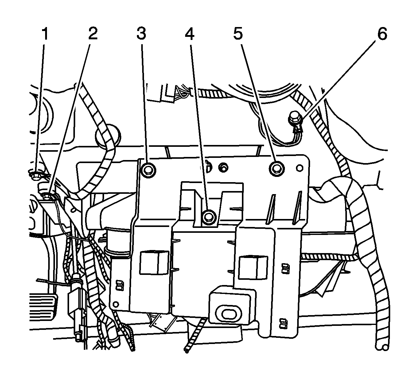
- Remove the vehicle location antenna module bracket bolts (3, 4, 5).
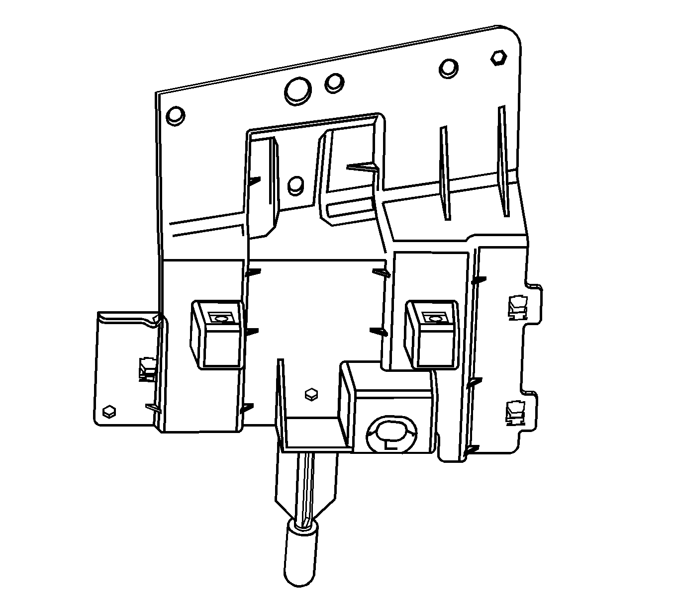
- Remove the communication interface module screws.
- Lower the communication interface module to the floor.
- Remove the vehicle location antenna module bracket.


Installation Procedure
- Align the communication interface module to the vehicle location antenna module bracket.
- Install the communication interface module screws.
- Align the vehicle location antenna module bracket to the locator on the I/P carrier (cross car beam).
- Start the bolts by hand to avoid cross threading. Install the vehicle location antenna module bracket bolts (3, 4, 5).
- Install the I/P trim pad. Refer to Instrument Panel Trim Pad Replacement in Instrument Panel, Gages, and Console.

Notice: Refer to Fastener Notice in the Preface section.
Tighten
Tighten the screws to 2 N·m (18 lb in).

Tighten
Tighten the bolts to 10 N·m (89 lb in).
