Tools Required
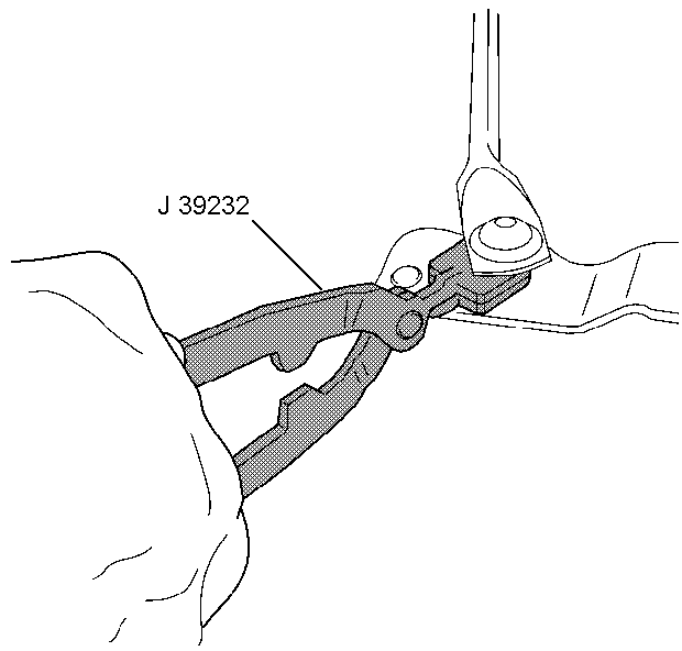
| • | J 39232 Wiper Transmission Separator |
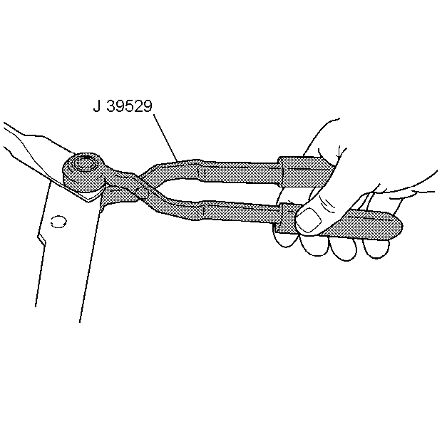
| • | J 39529 Wiper Transmission Installer |
Removal Procedure
- Remove the air inlet grille panel. Refer to Air Inlet Grille Panel Replacement in Body Front End.
- Disconnect the wiper transmission from the wiper motor crank arm using the J 39232 .
- Disconnect the electrical connector from the wiper motor.
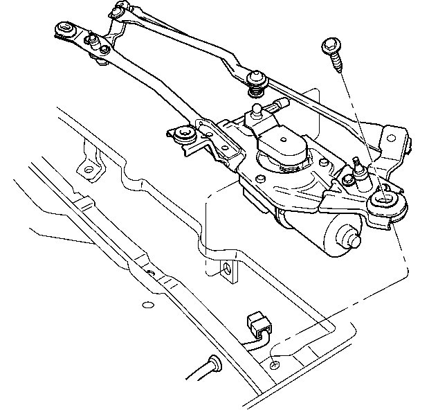
- Remove the screws from the wiper drive system module.
- Remove the wiper drive system module from the vehicle.
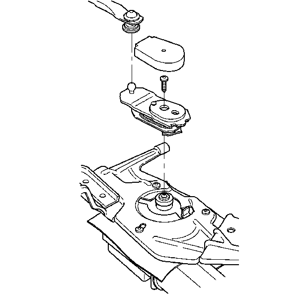
- Remove the rubber boot from the wiper motor crank arm.
- Loosen the wiper motor crank arm screw.
- Tap on the wiper motor crank arm screw with a soft-faced mallet while holding up on the wiper motor crank arm until the wiper motor crank arm is loose on the wiper motor.
- Remove the wiper motor crank arm screw and wiper motor crank arm from the wiper motor.
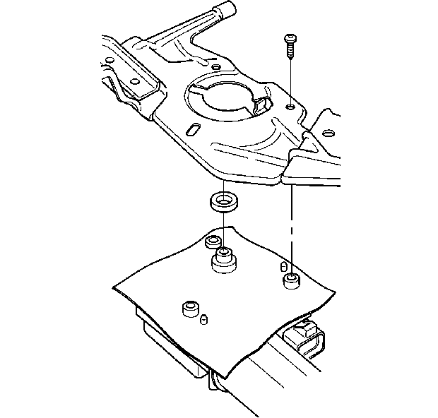
- Remove the wiper motor screws.
- Remove the wiper motor from the wiper drive system module.
- Remove the shaft seal and the water shield from the wiper motor.
Installation Procedure
- Install the water shield and shaft seal on the wiper motor.
- Install the wiper motor onto the wiper drive system module.
- Install the wiper motor screws.
- Connect the electrical connector to the wiper motor.
- Turn ON the ignition.
- Turn the wiper switch to DELAY.
- Turn OFF the ignition when the wiper motor is paused in the innerwipe position.
- Disconnect the electrical connector from the wiper motor.
- Install the rubber boot onto the wiper motor crank arm.
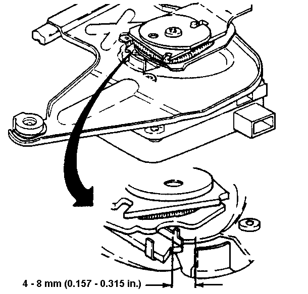
- Install the wiper motor crank arm onto the wiper motor.
- Measure the gap between the wiper motor crank arm and the bracket tab. If the gap is not 4-8 mm (0.157-0.314 in), remove the wiper motor crank arm and repeat the installation.
- Install the wiper motor crank arm screw.
- Align the wiper drive system module onto the vehicle.
- Install the wiper drive system module screws.
- Install the wiper transmission onto the wiper motor crank arm using the J 39529 .
- Connect the electrical connector to the wiper motor.
- Install the air inlet grille panel. Refer to Air Inlet Grille Panel Replacement in Body Front End.
- Operate the windshield wipers and inspect for proper operation.

Notice: Use the correct fastener in the correct location. Replacement fasteners must be the correct part number for that application. Fasteners requiring replacement or fasteners requiring the use of thread locking compound or sealant are identified in the service procedure. Do not use paints, lubricants, or corrosion inhibitors on fasteners or fastener joint surfaces unless specified. These coatings affect fastener torque and joint clamping force and may damage the fastener. Use the correct tightening sequence and specifications when installing fasteners in order to avoid damage to parts and systems.
Tighten
Tighten the wiper motor screws to 7 N·m (62 lb in).

Tighten
Tighten the wiper motor crank arm screw to 16 N·m (142 lb in).

Tighten
Tighten the wiper drive system module screws to 10 N·m
(88 lb in).
