Tool Required
J 37088-A tool set, Fuel Pipe Quick-Connect Separator
Removal Procedure
- Relieve the fuel system fuel pressure. Refer to Fuel Pressure Relief .
- Clean all engine fuel pipe connections.
- Clean the areas that surround the engine fuel pipe connections.
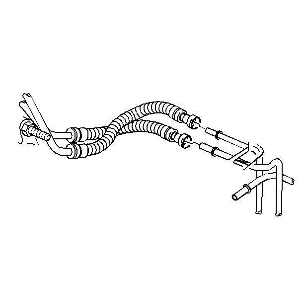
- Disconnect the fuel feed and the fuel return pipe quick-connect fitting in the engine compartment. Refer to Metal Collar Quick Connect Fitting Service .
- Raise the vehicle. Refer to Lifting and Jacking the Vehicle in General Information.
- Disconnect the fuel return pipe quick-connect fitting in front of the fuel tank. Refer to Metal Collar Quick Connect Fitting Service .
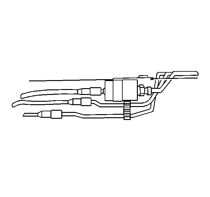
- Disconnect the fuel feed pipe threaded fitting on the engine side of the in-pipe fuel filter.
- Cap the in-pipe fuel filter pipe, the fuel feed pipe, and the fuel return pipe as needed in order to stop any fuel leakage.
- Disconnect the fuel feed, the fuel return and the evaporative emissions (EVAP) pipes.
- Remove the EVAP pipe attaching hardware.
- Note the position of the fuel and the EVAP pipes, and the fuel and the EVAP pipe attaching hardware for installation.
- Inspect the pipes for bends, for kinks, and for cracks.
- Repair or replace the pipe or pipes as required.

Caution: In order to reduce the risk of fire and personal injury observe the
following items:
• Replace all nylon fuel pipes that are nicked, scratched or damaged
during installation, do not attempt to repair the sections of the nylon fuel
pipes • Do not hammer directly on the fuel harness body clips when installing
new fuel pipes. Damage to the nylon pipes may result in a fuel leak. • Always cover nylon vapor pipes with a wet towel before using a
torch near them. Also, never expose the vehicle to temperatures higher than
115°C (239°F) for more than one hour, or more than 90°C (194°F)
for any extended period. • Apply a few drops of clean engine oil to the male pipe ends before
connecting fuel pipe fittings. This will ensure proper reconnection and prevent
a possible fuel leak. (During normal operation, the O-rings located in the
female connector will swell and may prevent proper reconnection if not lubricated.)
Notice: Cap the fittings and plug the holes when servicing the fuel system in order to prevent dirt and other contaminants from entering the open pipes and passages.
Important: Always maintain cleanliness when servicing fuel system components.

Installation Procedure
- Install the new fuel feed, the fuel return, the EVAP pipes, and the fuel and EVAP pipe attaching hardware as noted during removal.
- Remove the caps from the in-pipe fuel filter pipe, the fuel feed pipe, and the fuel return pipe.
- Connect the fuel return pipe quick-connect fitting in front of the fuel tank. Refer to Metal Collar Quick Connect Fitting Service .
- Connect the fuel feed pipe threaded fitting at the outlet of the in pipe fuel filter.
- Lower the vehicle.
- Connect the fuel feed, and the fuel return pipe quick-connect fittings in the engine compartment. Refer to Metal Collar Quick Connect Fitting Service .
- Inspect and ensure that all of the fuel pipe bundle clips and the fasteners are properly installed.
- Add the fuel, and reinstall the fuel tank filler pipe cap.
- Lower the vehicle.
- Connect the negative battery cable. Refer to Battery Negative Cable Disconnection and Connection in Engine Electrical.
- Use the following procedure in order to inspect for leaks:

Caution: In order to reduce the risk of fire and personal injury observe the
following items:
• Replace all nylon fuel pipes that are nicked, scratched or damaged
during installation, do not attempt to repair the sections of the nylon fuel
pipes • Do not hammer directly on the fuel harness body clips when installing
new fuel pipes. Damage to the nylon pipes may result in a fuel leak. • Always cover nylon vapor pipes with a wet towel before using a
torch near them. Also, never expose the vehicle to temperatures higher than
115°C (239°F) for more than one hour, or more than 90°C (194°F)
for any extended period. • Apply a few drops of clean engine oil to the male pipe ends before
connecting fuel pipe fittings. This will ensure proper reconnection and prevent
a possible fuel leak. (During normal operation, the O-rings located in the
female connector will swell and may prevent proper reconnection if not lubricated.)
Notice: Always re-attach the fuel lines and fuel filter with all original type fasteners and hardware.
Do not repair sections of fuel pipes.Notice:
• Secure the fuel pipes to the frame in order to prevent chafing.
Maintain a minimum of 13 mm (½ inch) clearance around
a pipe in order to prevent contact and chafing. Maintain a minimum of 19 mm
(¾ inch) around any moving part. • Do not allow the fuel pipes to come into contact with the fuel
tank or underbody.
Important: If the fuel line bundle attaching hardware is damaged or broken, replace it.
Notice: Use the correct fastener in the correct location. Replacement fasteners must be the correct part number for that application. Fasteners requiring replacement or fasteners requiring the use of thread locking compound or sealant are identified in the service procedure. Do not use paints, lubricants, or corrosion inhibitors on fasteners or fastener joint surfaces unless specified. These coatings affect fastener torque and joint clamping force and may damage the fastener. Use the correct tightening sequence and specifications when installing fasteners in order to avoid damage to parts and systems.
Tighten
Tighten the in-pipe fuel filter fitting to 30 N·m (22 lb ft).

Notice: Do not attempt to straighten any kinked nylon fuel lines. Replace any kinked nylon fuel feed or return pipes in order to prevent damage to the vehicle.

| 11.1. | Turn ON the ignition, for 2 seconds. |
| 11.2. | Turn OFF the ignition, for 10 seconds. |
| 11.3. | Turn ON the ignition. |
| 11.4. | Inspect for fuel leaks. |
