| |||||||
|---|---|---|---|---|---|---|---|
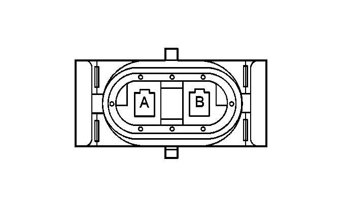
Connector Part Information |
| ||||||
Pin | Wire Color | Circuit No. | Function | ||||
A | BLK | 1050 | Ground | ||||
B | DK GRN | 59 | A/C Compressor Clutch Solenoid Feed | ||||
| |||||||
|---|---|---|---|---|---|---|---|
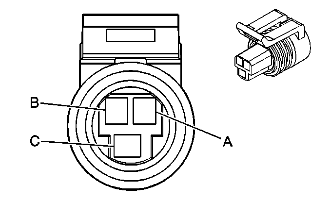
Connector Part Information |
| ||||||
Pin | Wire Color | Circuit No. | Function | ||||
A | BLK | 2751 | Sensor Ground | ||||
B | GRY | 2700 | Reference Voltage Feed-5 Volts | ||||
C | RED/BLK | 380 | A/C Refrigerent Pressure Signal | ||||
| |||||||
|---|---|---|---|---|---|---|---|
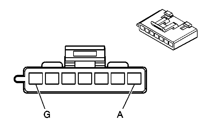
Connector Part Information |
| ||||||
Pin | Wire Color | Circuit No. | Function | ||||
A | TAN | 63 | Blower Switch Output Medium 1 | ||||
B | YEL | 60 | Blower Switch Ouput-Low | ||||
C | PPL | 73 | Blower Switch Output Medium 3 | ||||
D | LT BLU | 72 | Blower Switch Output Medium 2 | ||||
E | BLK | 150 | Ground | ||||
F | ORN | 52 | Blower Switch Ouput-High | ||||
G | ORN | 40 | Fused Battery Feed | ||||
| |||||||
|---|---|---|---|---|---|---|---|
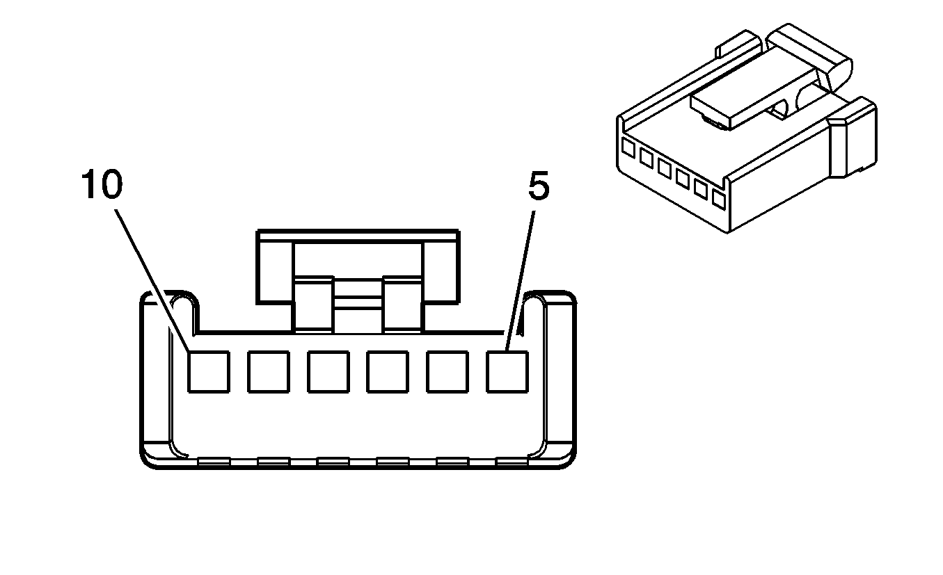
Connector Part Information |
| ||||||
Pin | Wire Color | Circuit No. | Function | ||||
5 | BRN | 541 | Fused Output-IGN 3 | ||||
6 | DK BLU | 1199 | Air Temperature Valve Motor Feed | ||||
7 | YEL | 61 | Ambient Outside/Inside Temperature Sensor Return | ||||
8 | -- | -- | Not Used | ||||
9 | LT BLU | 733 | Temperature Valve Position Signal (w/CJ2) | ||||
10 | LT BLU/BLK | 1688 | 5 Volts Reference | ||||

| |||||||
|---|---|---|---|---|---|---|---|
Connector Part Information |
| ||||||
Pin | Wire Color | Circuit No. | Function | ||||
5 | BRN | 541 | Fused Output-IGN 3 | ||||
6 | WHT/BLK | 1236 | Air Temperature Valve Motor Feed-Passenger | ||||
7 | YEL | 61 | Sensor Return - Outside/Inside | ||||
8 | -- | -- | Not Used | ||||
9 | DK BLU | 1646 | RH Temperature Valve Position Signal | ||||
10 | LT BLU/BLK | 1688 | 5 Volt Reference | ||||
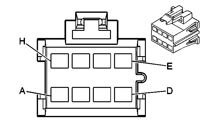
| |||||||
|---|---|---|---|---|---|---|---|
Connector Part Information |
| ||||||
Pin | Wire Color | Circuit No. | Function | ||||
A | WHT | 119 | Mode Switch Output | ||||
B | BRN | 41 | Fused Igition 3 Feed | ||||
C | ORN | 52 | Blower Switch Output-High | ||||
D | -- | -- | Not Used | ||||
E | PPL | 73 | Blower Switch Output-Medium 3 | ||||
F | LT BLU | 72 | Blower Switch Output-Medium 2 | ||||
G | TAN | 63 | Blower Switch Output-Medium 1 | ||||
H | YEL | 60 | Blower Switch Output-Low | ||||
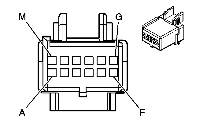
| |||||||
|---|---|---|---|---|---|---|---|
Connector Part Information |
| ||||||
Pin | Wire Color | Circuit No. | Function | ||||
A | WHT | 119 | Blower Switch Output-OFF | ||||
B | DK GRN/ WHT | 762 | A/C Request Signal | ||||
C | BRN | 541 | Fuesd Ignition- 3 Feed | ||||
D | WHT | 193 | Rear Defogger ON Indicator -Relay Coil Feed | ||||
E | ORN | 640 | Fused Battrery Feed | ||||
F | LT GRN | 273 | HVAC Control Signal-Not OFF | ||||
G | LT BLU | 733 | Temperature Valve Position Signal | ||||
H | YEL | 271 | HVAC Control Siganl-MAX | ||||
J | GRY | 8 | Interior Lamp Dim Signal | ||||
K | BLK | 150 | Ground | ||||
L | PPL | 272 | HVAC Control Signal-Defrost | ||||
M | GRY/BLK | 308 | Park Lamp Switch Signal-Park Lamps ON | ||||
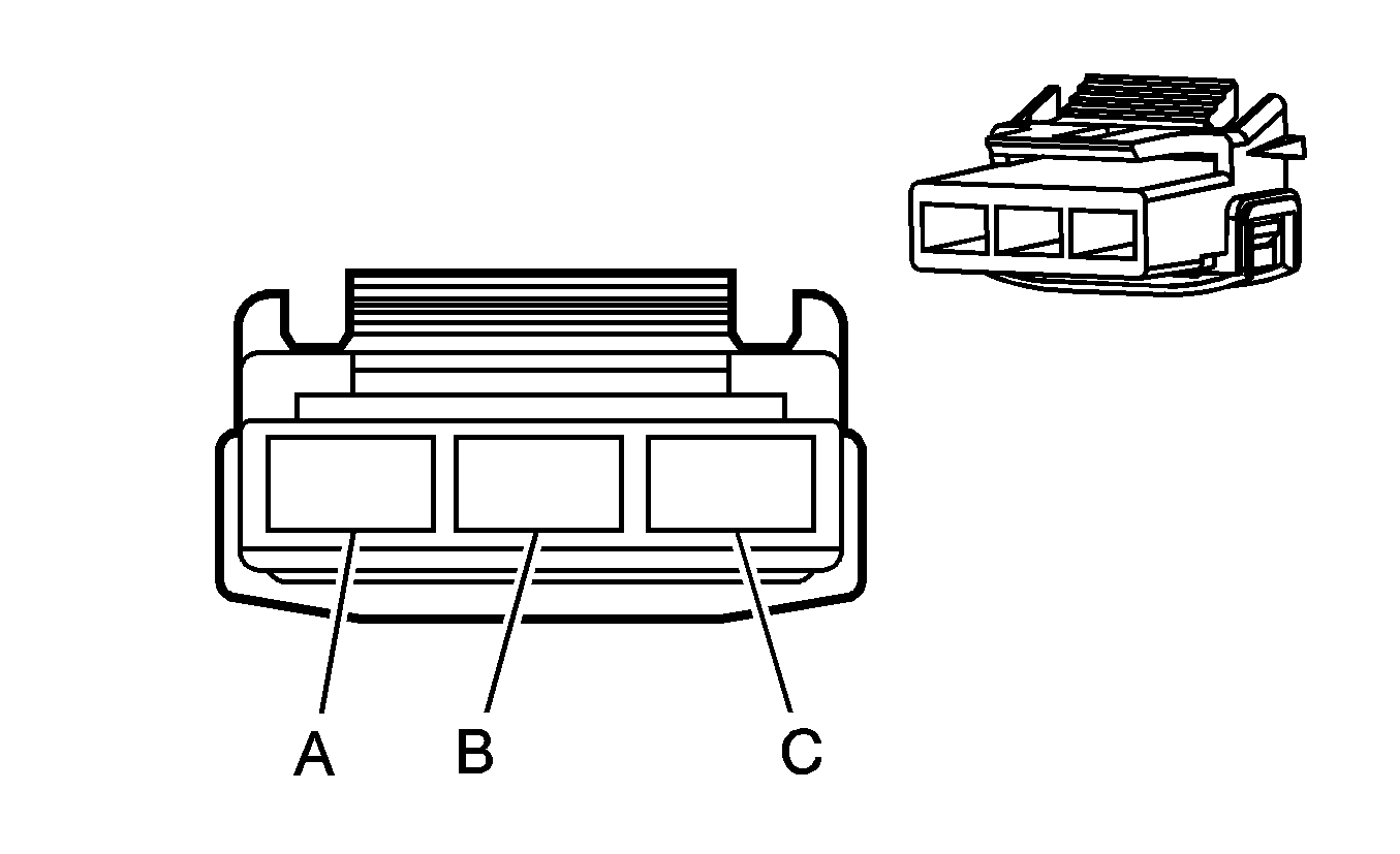
| |||||||
|---|---|---|---|---|---|---|---|
Connector Part Information |
| ||||||
Pin | Wire Color | Circuit No. | Function | ||||
A | LT GRN | 273 | HVAC Control Signal-Defrost | ||||
B | PPL | 272 | HVAC Control Signal-Not OFF | ||||
C | YEL | 271 | HVAC Control Signal-MAX | ||||
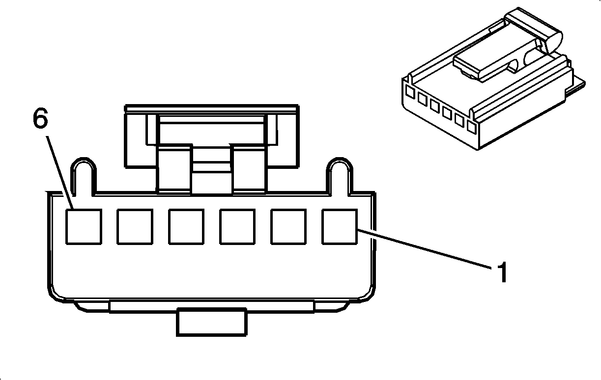
| |||||||
|---|---|---|---|---|---|---|---|
Connector Part Information |
| ||||||
Pin | Wire Color | Circuit No. | Function | ||||
1 | LT GRN/BLK | 366 | Defrost Solenoid Control | ||||
2 | RED | 362 | Heater Solenoid Control | ||||
3 | PPL | 361 | Bi-Level Solenoid Control | ||||
4 | TAN | 363 | A/C Solenoid Control | ||||
5 | LT BLU | 706 | Recirclation Solenoid Control | ||||
6 | BRN | 41 | Fused IGN 1 Feed | ||||
