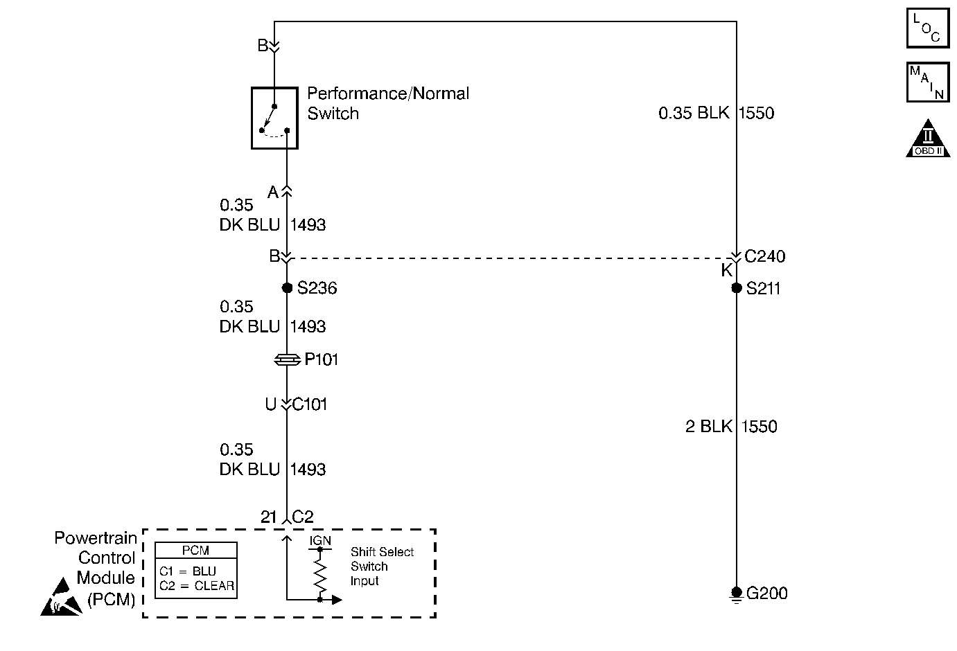
Circuit Description
The shift select system allows the driver to select one of two shift patterns, NORMAL or PERFORMANCE. The PERFORMANCE / NORMAL switch is a normally open switch, that when closed, provides a ground path to the powertrain control module (PCM). When the PCM receives the ground signal, it switches into the PERFORMANCE mode and the following changes occur:
| • | Upshifts occur at a higher engine speed. |
| • | Downshifts occur at a lower percentage throttle position. |
| • | Engine torque output is increased in 2nd and 3rd gear. |
Diagnostic Aids
| • | Inspect the wiring at the PCM connector, the PERFORMANCE / NORMAL switch connector and all other circuit connecting points for the following conditions: |
| - | A backed out terminal |
| - | A damaged terminal |
| - | Reduced terminal tension |
| - | A chafed wire |
| - | A broken wire inside the insulation |
| - | Moisture intrusion |
| - | Corrosion |
| • | Verify that any aftermarket electronic equipment is properly installed. Improperly installed aftermarket electronic equipment may modify the integrity of other systems. |
| • | Refer to General Electrical Diagnosis in Wiring Systems. |
Test Description
The numbers below refer to the step numbers on the diagnostic table.
-
This step verifies that the Performance/Normal Switch is functioning properly.
-
This step determines if a condition exists in circuit 1550.
Step | Action | Value(s) | Yes | No |
|---|---|---|---|---|
Does the scan tool indicate Normal and Performance appropriately? | -- | Go to Symptom Diagnosis | ||
2 |
Does the Shift Mode status on the scan tool change? | -- | ||
Does the Shift Mode status on the scan tool change? | -- | |||
4 | Does the Shift Mode parameter on the scan tool always display Performance? | -- | ||
5 | Inspect circuit 1493 (DK BLUE) for a short to ground. Was a condition found? | -- | ||
6 | Inspect circuit 1493 (DK BLUE) for an open. Was a condition found? | -- | ||
7 | Inspect circuit 1550 (BLK) for an open. Was a condition found? | -- | Go to Diagnostic Aids | |
8 | Replace the Performance/Normal switch. Is the replacement complete? | -- | -- | |
9 | Inspect the PCM connectors for bent, damaged or backed out connector pins. Was a condition found? | -- | ||
10 | Replace PCM. Refer to Powertrain Control Module Replacement/Programming in Engine Controls. Is the replacement complete? | -- | -- | |
11 | Repair the circuit as necessary. Refer to Wiring Repairs in Wiring Systems. Is the repair complete? | -- | -- | |
12 | Repair the connector as necessary. Refer to Wiring Repairs in Wiring Systems. Is the repair complete? | -- | -- | |
13 |
Does the vehicle operate properly? | -- | System OK |
