Intake Manifold Replacement Upper
Removal Procedure
Important: This engine uses a sequential multiport fuel injection system. Connect the injector wiring harness connectors to their appropriate fuel injector or exhaust emissions and engine performance may be seriously affected.
- Disconnect the battery ground (negative) cable. Refer to Refer to Battery Negative Cable Disconnection and Connection in Engine Electrical.
- Disconnect the vacuum hose connection from the throttle body air inlet duct.
- Disconnect the wiring harness connection from the intake air temperature (IAT) sensor in the throttle body air inlet duct. Refer to Intake Air Temperature Sensor Replacement in Engine Controls - 3.1L.
- Remove the throttle body air inlet duct.
- Drain the engine coolant from the cooling system. Refer to Cooling System Draining and Filling in Engine Cooling.
- Remove the accelerator control and cruise control cables with bracket from the throttle body. Refer to Accelerator Control Cable Replacement in Engine Controls - 3.1L.
- Disconnect the wiring harness connectors from the throttle body.
- Disconnect the (left) front spark plug wires. Refer to Spark Plug Wire Harness Replacement in Engine Electrical.
- Disconnect the wiring harness attachment clips.
- Disconnect the thermostat bypass pipe coolant hoses from the throttle body.
- Remove the ignition coil bracket with the coils, the purge solenoid and the vacuum canister solenoid. Refer to Ignition Coil Replacement and Evaporative Emission Canister Purge Solenoid Valve Replacement in Engine Controls - 3.1L.
- Disconnect the vacuum hose at the manifold air pressure (MAP) sensor and upper intake manifold.
- Remove the manifold air pressure (MAP) sensor and the bracket. Refer to Manifold Absolute Pressure Sensor Replacement in Engine Controls - 3.1L.
- Disconnect the emission control vacuum harness.
- Disconnect the vacuum hose connections from the upper intake manifold.
- Remove the generator brace. Refer to Generator Brace Replacement in Engine Electrical.
- Remove the generator bracket. Refer to Battery Replacement .
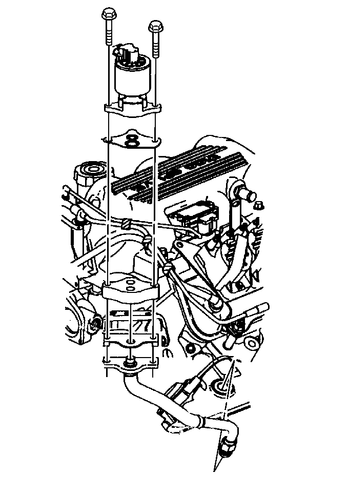
- Remove the exhaust gas recirculation (EGR) valve. Refer to Exhaust Gas Recirculation Valve Replacement in Engine Controls - 3.1L.
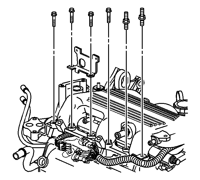
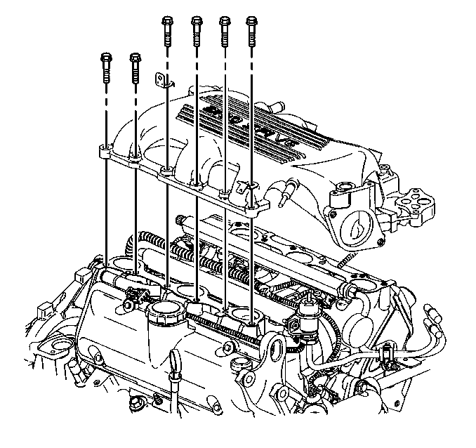
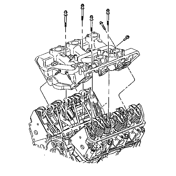
- Remove the right (rear) upper intake manifold bolts and studs.
- Remove the left (front) upper intake manifold bolts.
- Remove the upper intake manifold.
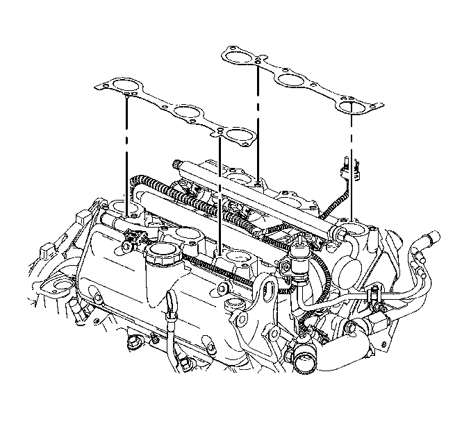
- Remove the upper intake manifold gasket.
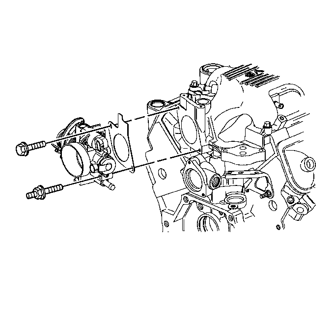
- If replacing the upper intake manifold, remove the throttle body. Refer to Throttle Body Assembly Replacement in Engine Controls - 3.1L.
- Clean the seal surfaces on the manifold with degreaser.
| • | Throttle position (TP) sensor |
| • | Idle air control (IAC) valve |
| • | Camshaft position (CMP) sensor wiring harness |
| • | Left (front) spark plug wire harness |
| • | Engine wiring harness |
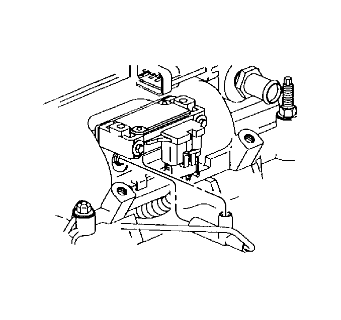
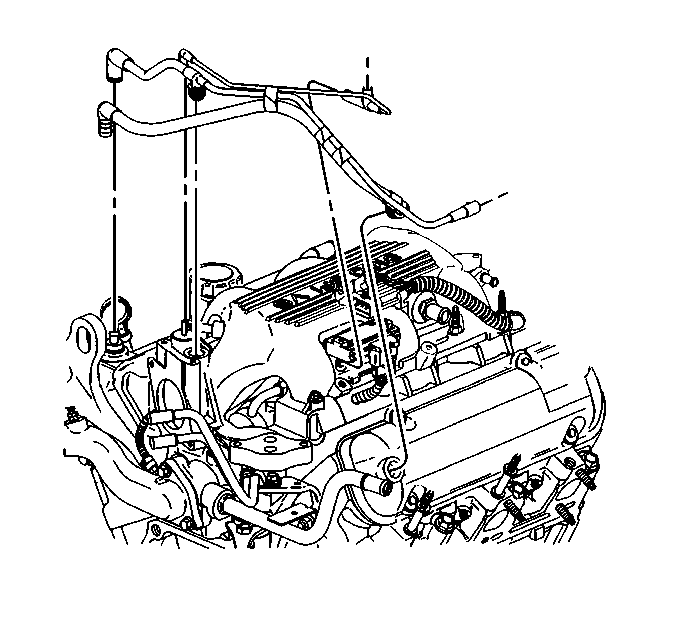
| • | Vacuum booster hose |
| • | Automatic transaxle vacuum modulator hose |
| • | Heater and air conditioning vacuum source hose |
| • | Fuel pressure regulator |
Installation Procedure
- If removed, install the throttle body. Refer to Throttle Body Assembly Replacement in Engine Controls - 3.1L.
- Install the upper intake manifold gasket.
- Install the upper intake manifold.
- Loosely install the left (front) upper intake manifold bolts.
- Loosely install the right (rear) upper intake manifold bolts and studs.
- Install the upper intake manifold bolts and studs.
- Install the exhaust gas recirculation (EGR) valve. Refer to Exhaust Gas Recirculation Valve Replacement in Engine Controls - 3.1L.
- Install the generator bracket. Refer to Battery Replacement .
- Install the generator brace. Refer to Generator Brace Replacement in Engine Electrical.
- Connect the vacuum hose connections to the upper intake manifold.
- Connect the emission control vacuum harness.
- Install the manifold air pressure (MAP) sensor and bracket. Refer to Manifold Absolute Pressure Sensor Replacement in Engine Controls - 3.1L.
- Connect the vacuum hose at the manifold air pressure (MAP) sensor and the upper intake manifold.
- Install the ignition coil bracket with the coils, the purge solenoid and the vacuum canister solenoid. Refer to Ignition Coil Replacement and Evaporative Emission Canister Purge Solenoid Valve Replacement in Engine Controls - 3.1L.
- Connect the thermostat bypass pipe coolant hoses to the throttle body.
- Connect the wiring harness attachment clips.
- Connect the left (front) spark plug wires. Refer to Spark Plug Wire Harness Replacement in Engine Electrical.
- Connect the wiring harness connectors to the throttle body.
- Install the accelerator control and cruise control cables with bracket to the throttle body. Refer to Accelerator Control Cable Replacement in Engine Controls - 3.1L.
- Fill the cooling system with engine coolant. Refer to Cooling System Draining and Filling in Engine Cooling.
- Install the throttle body air inlet duct.
- Connect the wiring harness connection to the intake air temperature (IAT) sensor in the throttle body air inlet duct. Refer to Intake Air Temperature Sensor Replacement in Engine Controls - 3.1L.
- Connect the vacuum hose connection to the throttle body air inlet duct.
- Connect the battery ground (negative) cable. Refer to Refer to Battery Negative Cable Disconnection and Connection in Engine Electrical.


Notice: Use the correct fastener in the correct location. Replacement fasteners must be the correct part number for that application. Fasteners requiring replacement or fasteners requiring the use of thread locking compound or sealant are identified in the service procedure. Do not use paints, lubricants, or corrosion inhibitors on fasteners or fastener joint surfaces unless specified. These coatings affect fastener torque and joint clamping force and may damage the fastener. Use the correct tightening sequence and specifications when installing fasteners in order to avoid damage to parts and systems.
Tighten
Tighten the upper intake manifold bolts and studs to 25 N·m
(18 lb ft).

| • | Vacuum booster hose |
| • | Automatic transaxle vacuum modulator hose |
| • | Heater and air conditioning vacuum source hose |
| • | Fuel pressure regulator |


| • | Camshaft position (CMP) sensor wiring harness |
| • | Left (front) spark plug wire harness |
| • | Engine wiring harness |
| • | Throttle position (TP) sensor |
| • | Idle air control (IAC) valve |
Intake Manifold Replacement Lower
Removal Procedure
- Disconnect the battery ground (negative) cable. Refer to Battery Negative Cable Disconnection and Connection in Engine Electrical.
- Remove the upper intake manifold. Refer to Intake Manifold Replacement .
- Remove the left (front) valve rocker arm cover. Refer to Valve Rocker Arm Cover Replacement .
- Remove the right (rear) valve rocker arm cover. Refer to Valve Rocker Arm Cover Replacement .
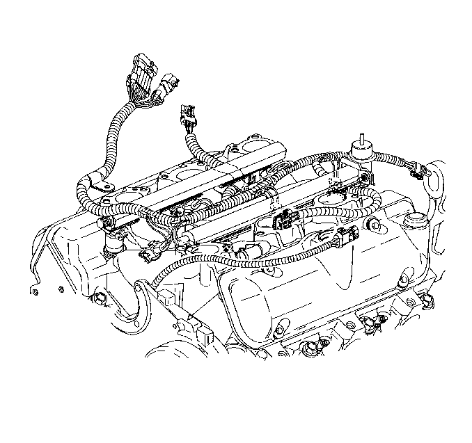
- Disconnect the engine coolant temperature (ECT) wiring harness.
- Disconnect and remove the fuel injector and manifold air pressure (MAP) wiring harness.
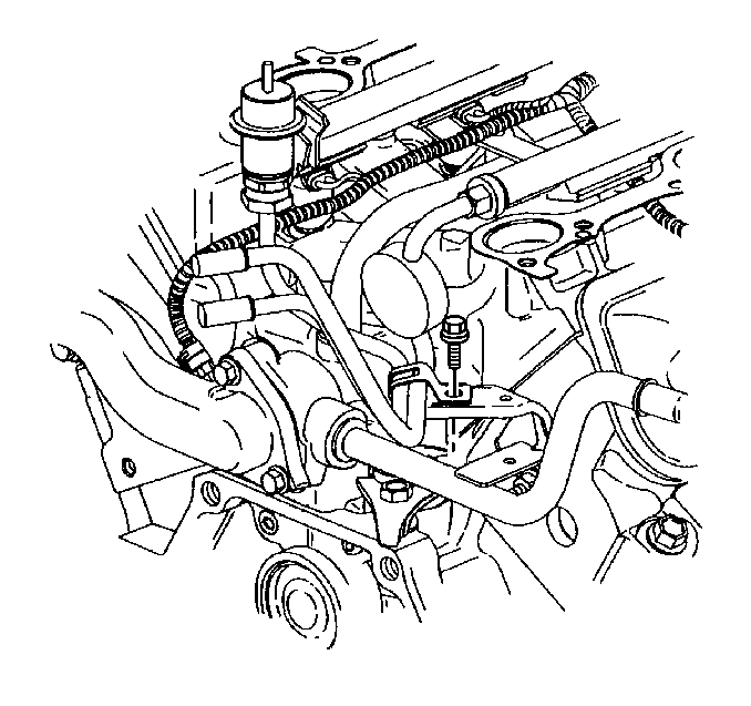
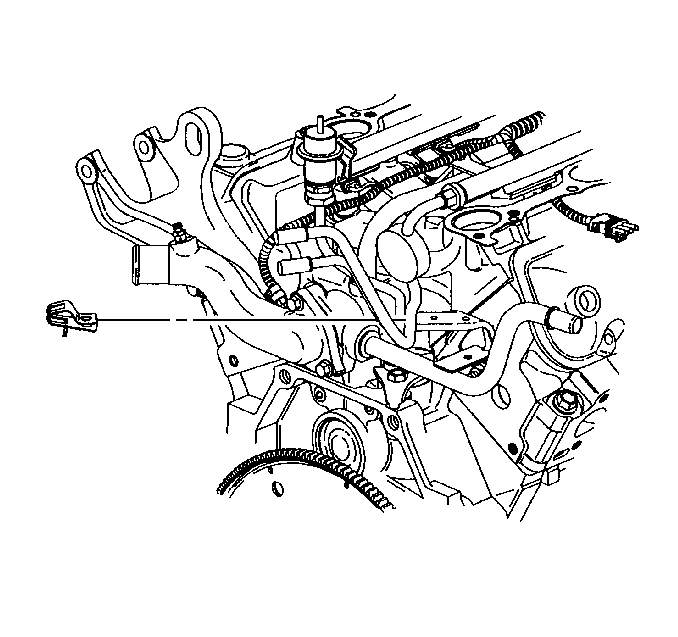
- Remove the fuel pipe clip bolt.
- Remove the fuel pipe clip.
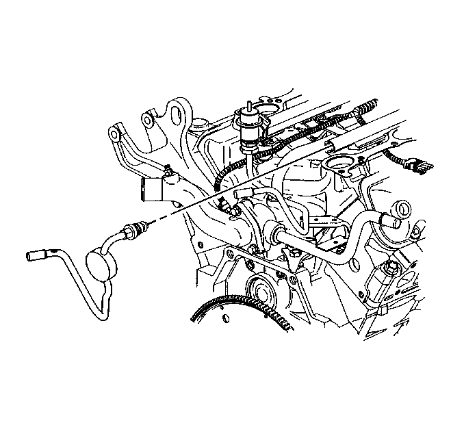
- Disconnect the fuel feed pipe from the fuel injector rail. Refer to Fuel Hose/Pipes Replacement - Filter to Engine in Engine Controls - 3.1L.
- Disconnect the fuel return pipe from the fuel injector rail. Refer to Fuel Hose/Pipes Replacement - Filter to Engine in Engine Controls - 3.1L.
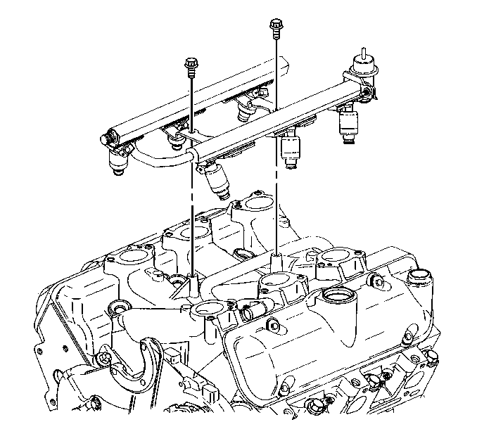
- Remove the fuel injector rail. Refer to Fuel Injection Fuel Rail Assembly Replacement in Engine Controls - 3.1L.
- Remove the power steering pump from the front engine cover and reposition. Refer to Power Steering Pump Replacement in Power Steering System.
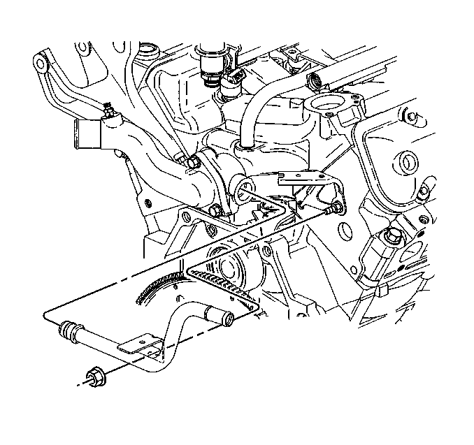
- Disconnect the heater inlet pipe with heater hose from the lower intake manifold and reposition.
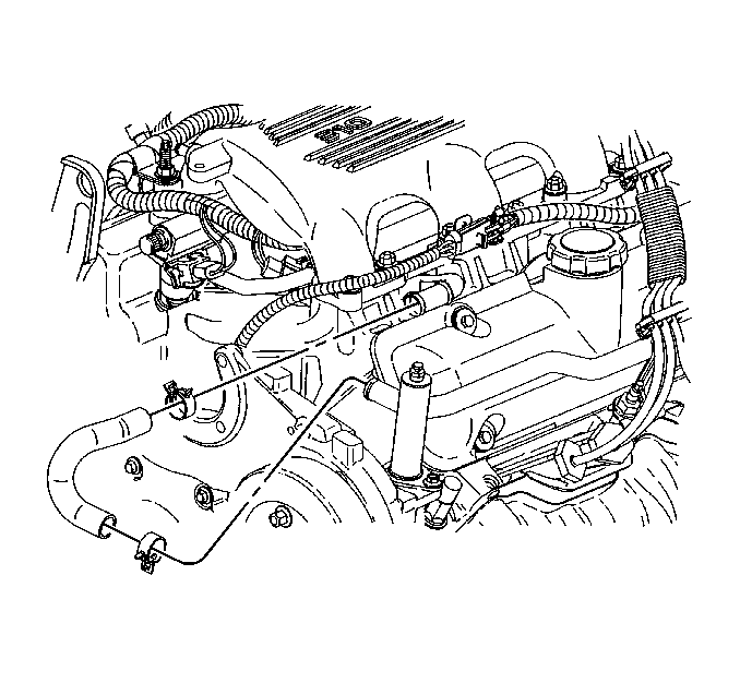
- Disconnect the radiator inlet hose from the engine. Refer to Radiator Inlet Hose Replacement in Engine Cooling.
- Disconnect the thermostat bypass hose from the thermostat bypass pipe and lower intake manifold pipe.
- Remove the lower intake manifold bolts.
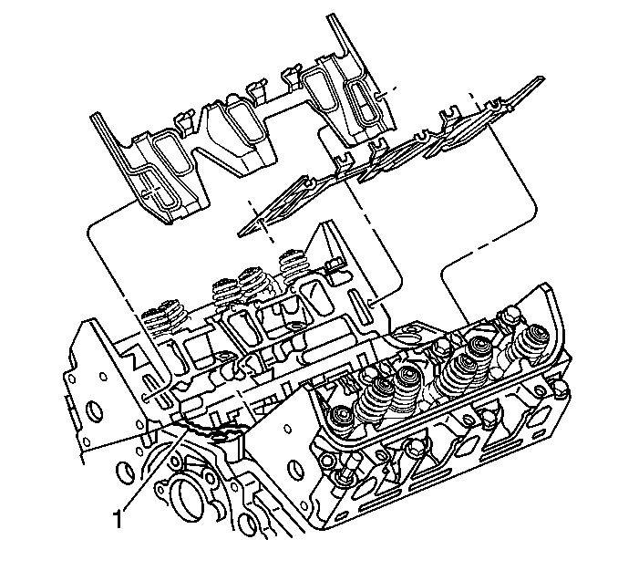
- Remove the lower intake manifold.
- Remove the valve rocker arms and pushrods. Refer to Valve Rocker Arm and Push Rod Replacement .
- Remove the lower intake manifold gaskets and seals.
- Clean the lower intake manifold gasket and seal surfaces on the cylinder heads and the engine block.
- Clean the gasket and seal surfaces on the lower intake manifold with degreaser.
- Remove all the loose RTV sealer.
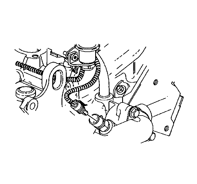
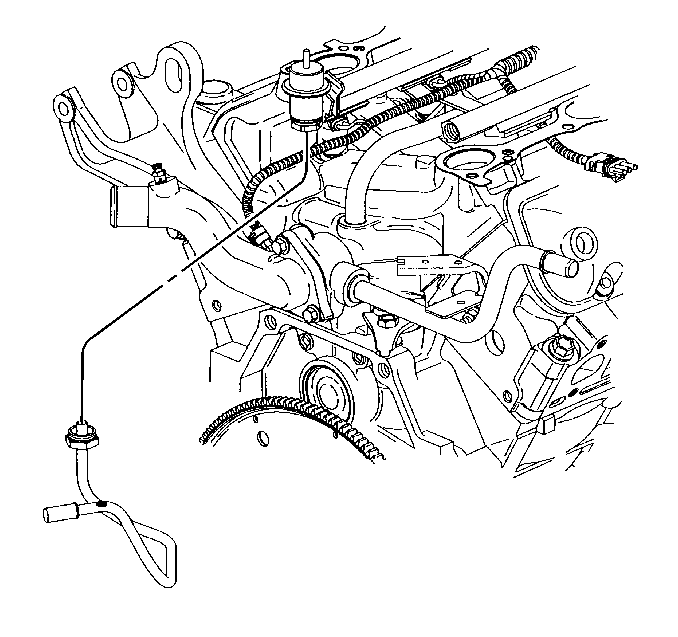
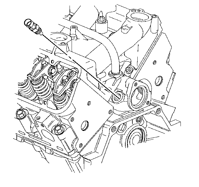
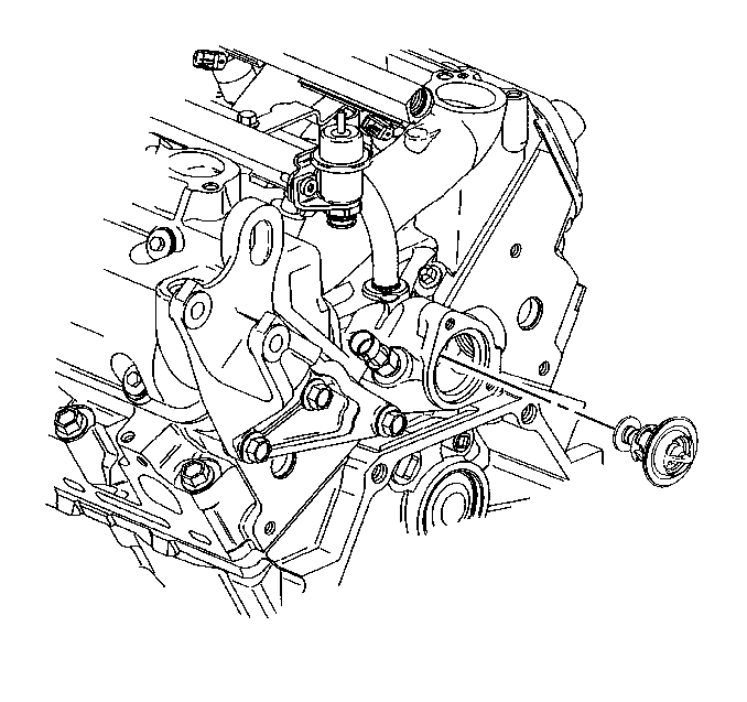
- Remove the engine coolant temperature (ECT) sensor.
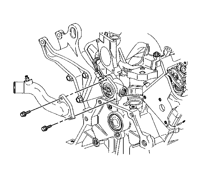
- Remove the water outlet bolts.
- Remove the water outlet.
- Remove the thermostat. Refer to Engine Coolant Thermostat Replacement in Engine Cooling.
Installation Procedure
- Install the thermostat. Refer to Engine Coolant Thermostat Replacement in Engine Cooling.
- Install the water outlet.
- Install the water outlet bolts.
- Install the engine coolant temperature (ECT) sensor.
- Install the lower intake manifold gaskets.
- With gaskets in place supply a small drop 8-10 mm (0.31-0.39 in) of RTV sealer GM P/N 12346141 (Canadian P/N 10953433) or equivalent to the 4 corners of the intake manifold to block joint (1).
- Connect the 2 small drops with a bead of RTV sealer that is between 8-10 mm (0.31-0.39 in) wide and 3.0-5.0 mm (0.12-0.20 in) thick (2).
- Install the valve rocker arms and pushrods. Refer to Valve Rocker Arm and Push Rod Replacement .
- Install the lower intake manifold.
- Install the lower intake manifold bolts.
- Tighten the lower intake manifold bolts in sequence to 7 N·m (62 lb in) on the first pass.
- Tighten the lower intake manifold bolts (1,2,3,4) in sequence to 13 N·m (115 lb in) on the final pass.
- Tighten the lower intake manifold bolts (5,6,7,8) in sequence to 25 N·m (18 lb in) on the final pass.
- Connect the thermostat bypass hose to the thermostat bypass pipe and lower intake manifold pipe.
- Connect the radiator inlet hose to the engine. Refer to Radiator Inlet Hose Replacement in Engine Cooling.
- Connect the heater inlet pipe and heater hose to the lower intake manifold.
- Install the power steering pump to the front engine cover. Refer to Power Steering Pump Replacement in Power Steering.
- Install the fuel rail assembly.
- Install the injector bolts.
- Connect the fuel return pipe to the fuel injector rail. Refer to Fuel Injection Fuel Rail Assembly Replacement in Engine Controls - 3.1L.
- Connect the fuel feed pipe to the fuel injector rail. Refer to Fuel Hose/Pipes Replacement - Filter to Engine in Engine Controls - 3.1L.
- Install the fuel pipe clip bolt.
- Install and connect the fuel injector and Manifold Air Pressure (MAP) wiring harness.
- Connect the Engine Coolant Temperature (ECT) wiring harness.
- Install the right valve rocker arm cover. Refer to Valve Rocker Arm Cover Replacement .
- Install the left valve rocker arm cover. Refer to Valve Rocker Arm Cover Replacement .
- Install the upper intake manifold. Refer to Intake Manifold Replacement .
- Connect the battery ground (negative) cable. Refer to Battery Negative Cable Disconnection and Connection in Engine Electrical.


Notice: Refer to Fastener Notice in the Preface section.
Tighten
Tighten the water outlet bolts to 25 N·m (18 lb ft).

Tighten
Tighten the engine coolant temperature (ECT) sensor to 23 N·m
(17 lb ft).
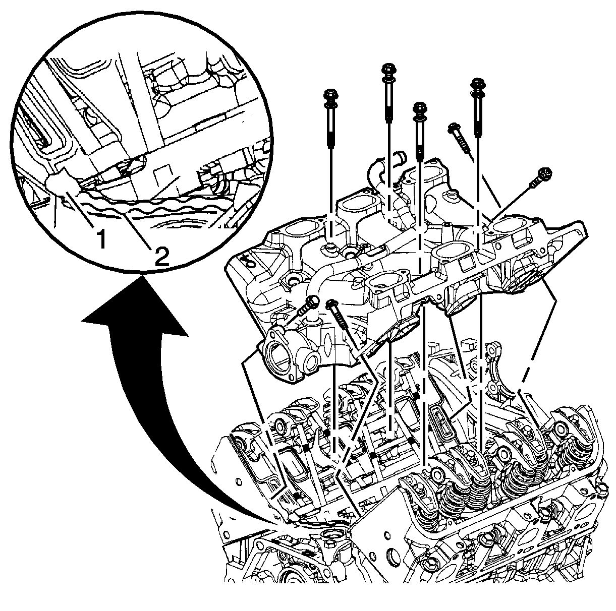
Important: All gasket-mating surfaces need to be free of oil, and foreign material. Use GM P/N 12346139 (Canadian P/N 10953463) or equivalent to clean surfaces.
Notice: Refer to Fastener Notice in the Preface section.

Important: All lower intake manifold bolts need to be cleaned, free of any foreign material, and reused only if new bolts are unavailable. Use GM P/N 1234382 (Canadian P/N 10953489) or equivalent and apply to the old intake manifold bolt threads.
Important: Manufacturer recommends the center bolts be fully torqued before the diagonal bolts to assure proper seal ability.
Important: Lower the intake manifold bolts in location 6 and 7 should be torqued to specification using a crows foot type tool.
Tighten


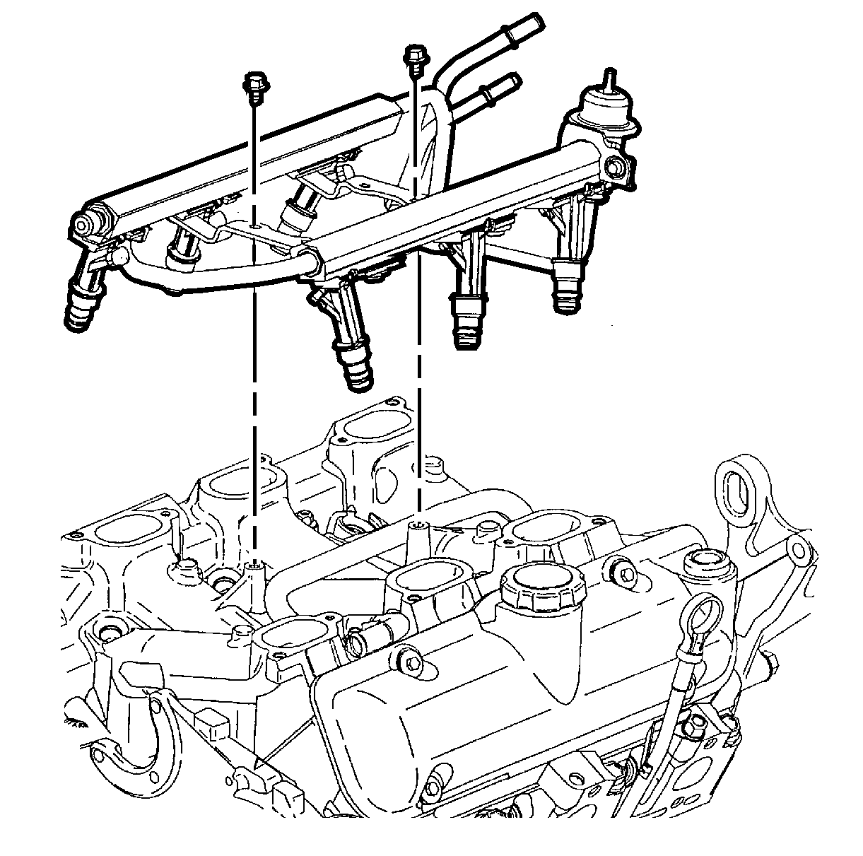
Important: Do not press on the fuel pressure regulator valve when installing the fuel injector rail assembly.
| 15.1. | Install the fuel injector O-rings using GM P/N 12345616 (Canadian P/N 993182) or equivalent. |
| 15.2. | Install the injector nozzles into the lower intake manifold injector bores. |
| 15.3. | Press on the injector rail using the palms of both hands until the injectors are fully seated. |
Tighten
Tighten the fuel injector rail bolts to 10 N·m (89 lb in).


Tighten
Tighten the fuel pipe clip bolt to 8 N·m (71 lb in).


