GM Service Manual Online
For 1990-2009 cars only
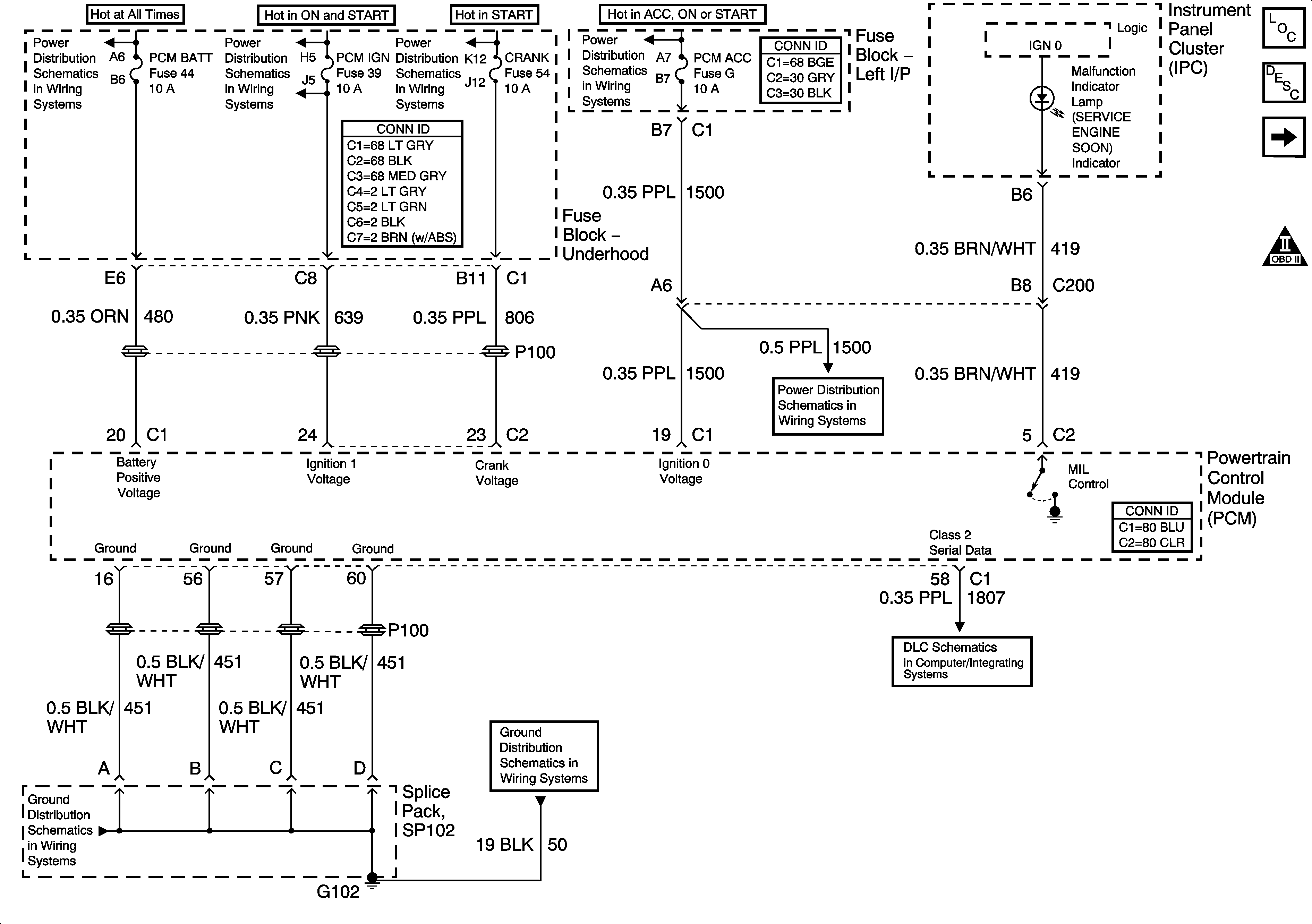
Figure 1:

Power, Ground, Serial Data and MIL


Object Number: 1391443  Size: FS
Master Electrical Component List
Powertrain Control Module Description
5 Volt Reference Bussing
Engine Controls Schematic Icons
L/H BEC BATT1, AUX PWR/CIGAR, PARK LPS, PCM BATT, PWR MIRROR, DR LOCK, TRUNK REL/RFA/Radio Amp Fuses and PWR SEAT Circuit Breaker
IGN SW-BATT2, WIPER, AIR BAG, TURN LPS, IGN MOD, B/U LP/BTSI, PCM IGN, F/P INJR, A/C BFC, AUTO TRANS, ABS/EVO/IGN Fuses
IGN SW BATT1, ERLS, HTR-A/C and CRANK Fuses
PCM ACC and IPC/BFC ACC Fuses
G102 and G104
G102 and G104
Data Link Connector (DLC) Schematics
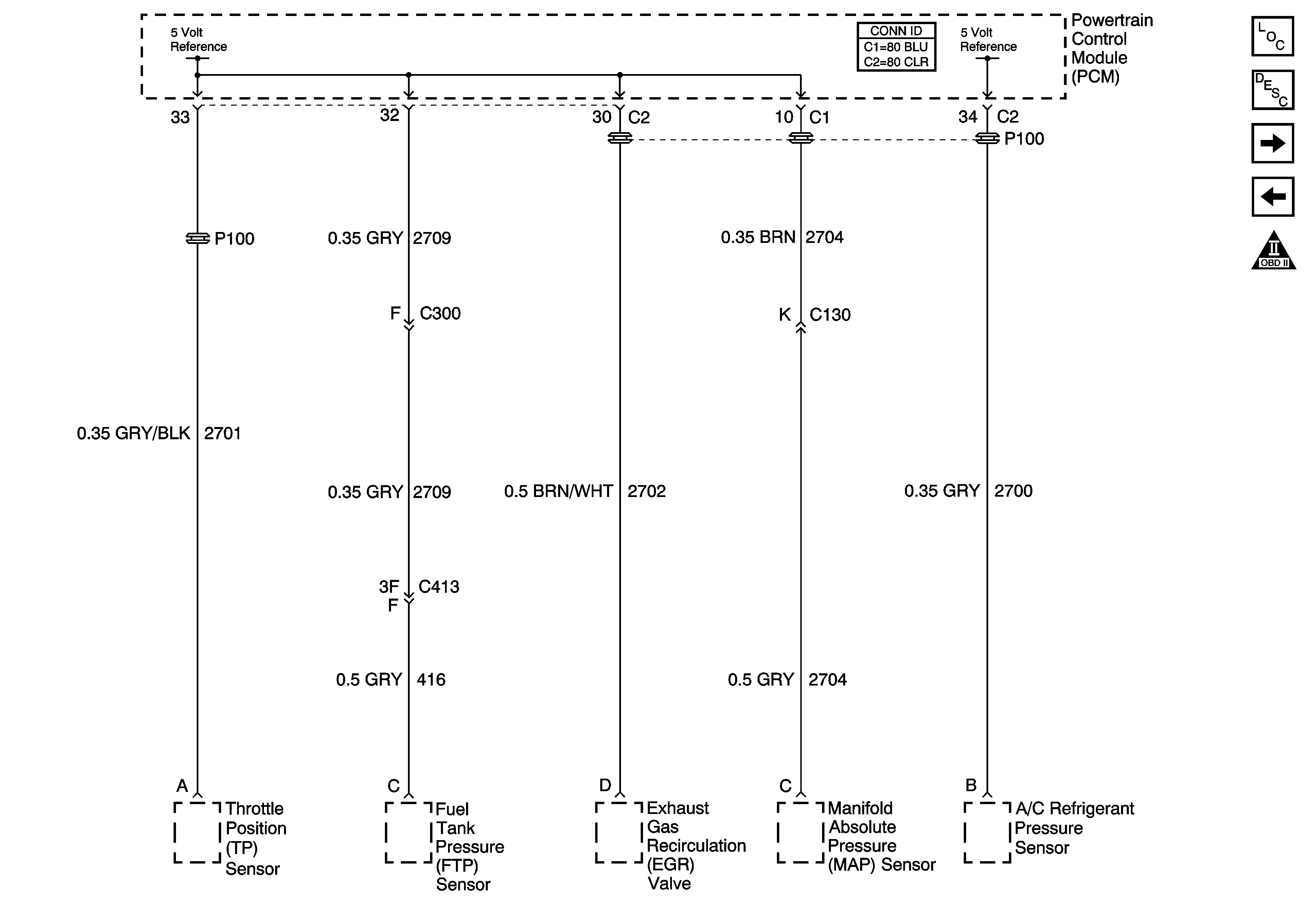
Figure 2:

5-Volt Reference Bussing


Object Number: 1391446  Size: FS
Master Electrical Component List
Powertrain Control Module Description
Low Reference Bussing
Power, Ground, Serial Data and MIL
Engine Controls Schematic Icons
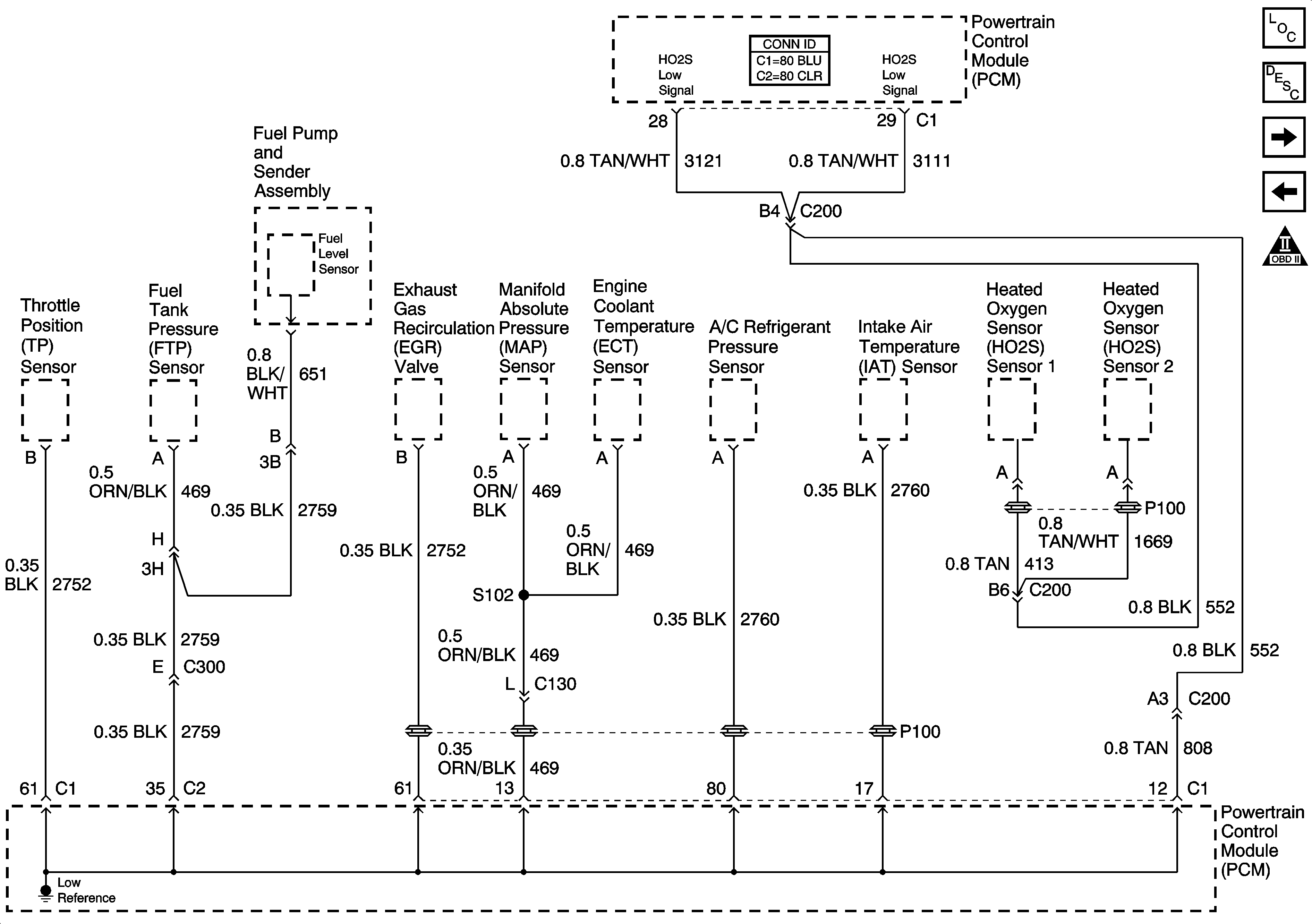
Figure 3:

Low Reference Bussing


Object Number: 1397957  Size: FS
Master Electrical Component List
Powertrain Control Module Description
Engine Data Sensors-Pressure and Temperature
5 Volt Reference Bussing
Engine Controls Schematic Icons
Figure 4:

Engine Data Sensors -- Pressure and Temperature
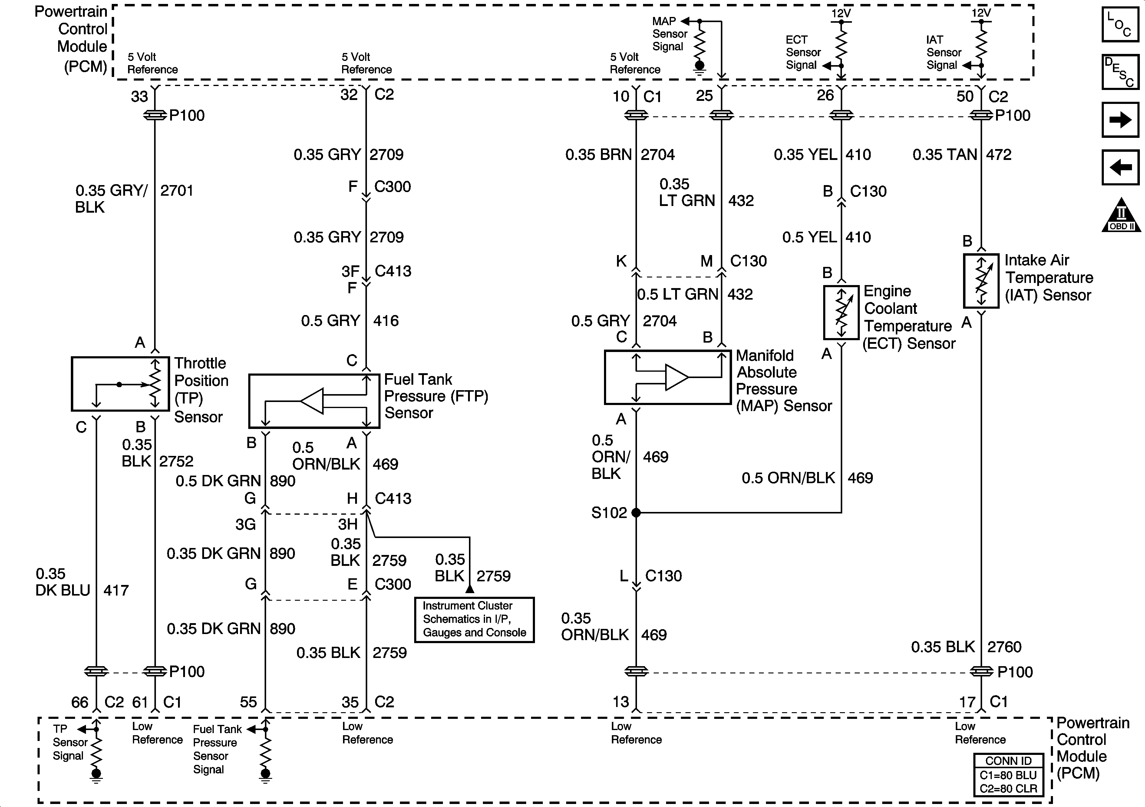

Object Number: 783001  Size: FS
Master Electrical Component List
Powertrain Control Module Description
Heated Oxygen Sensors
Low Reference Bussing
Engine Controls Schematic Icons
Fuel Level and Oil Pressure
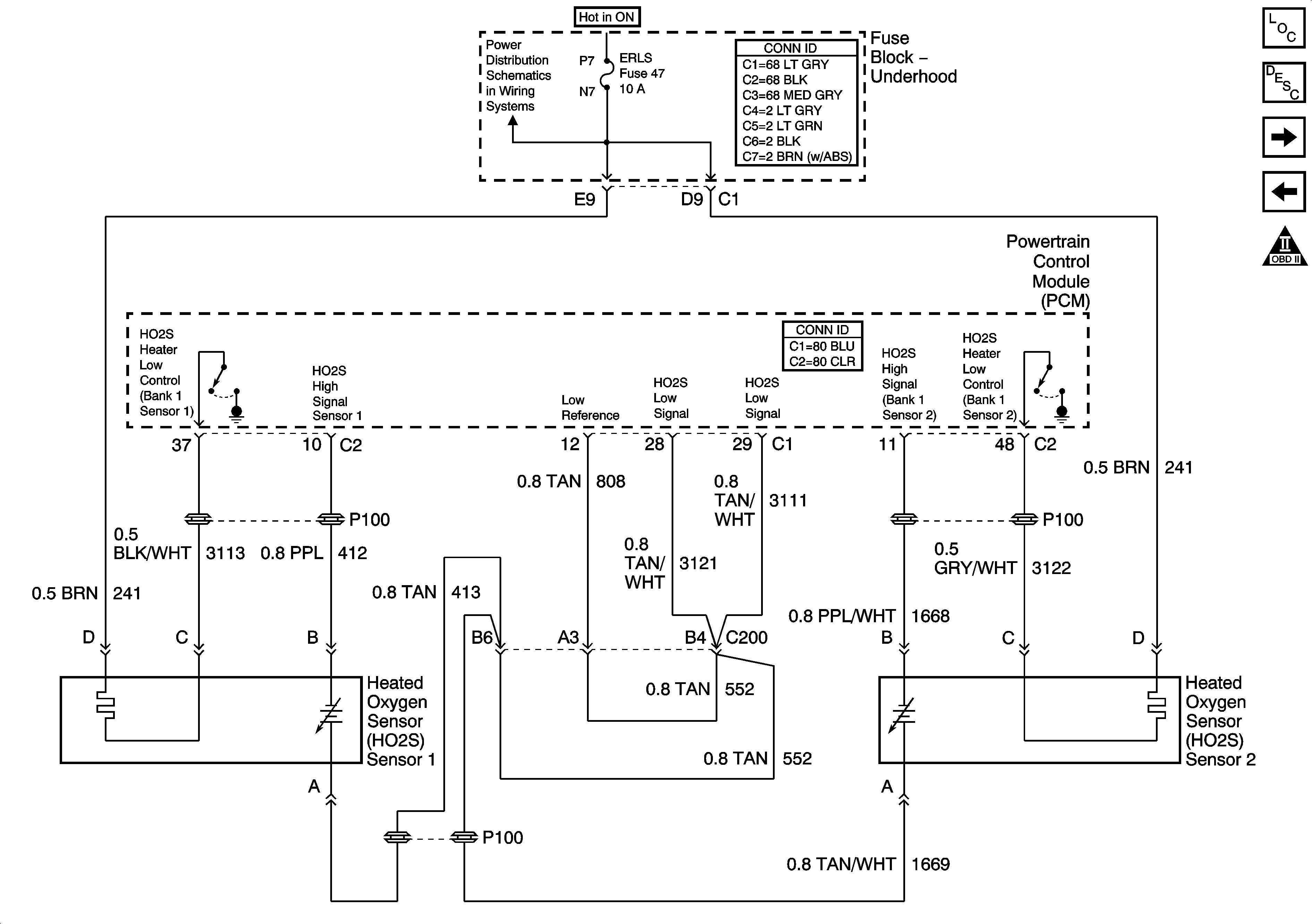
Figure 5:

Heated Oxygen Sensors


Object Number: 1391456  Size: FS
Master Electrical Component List
Powertrain Control Module Description
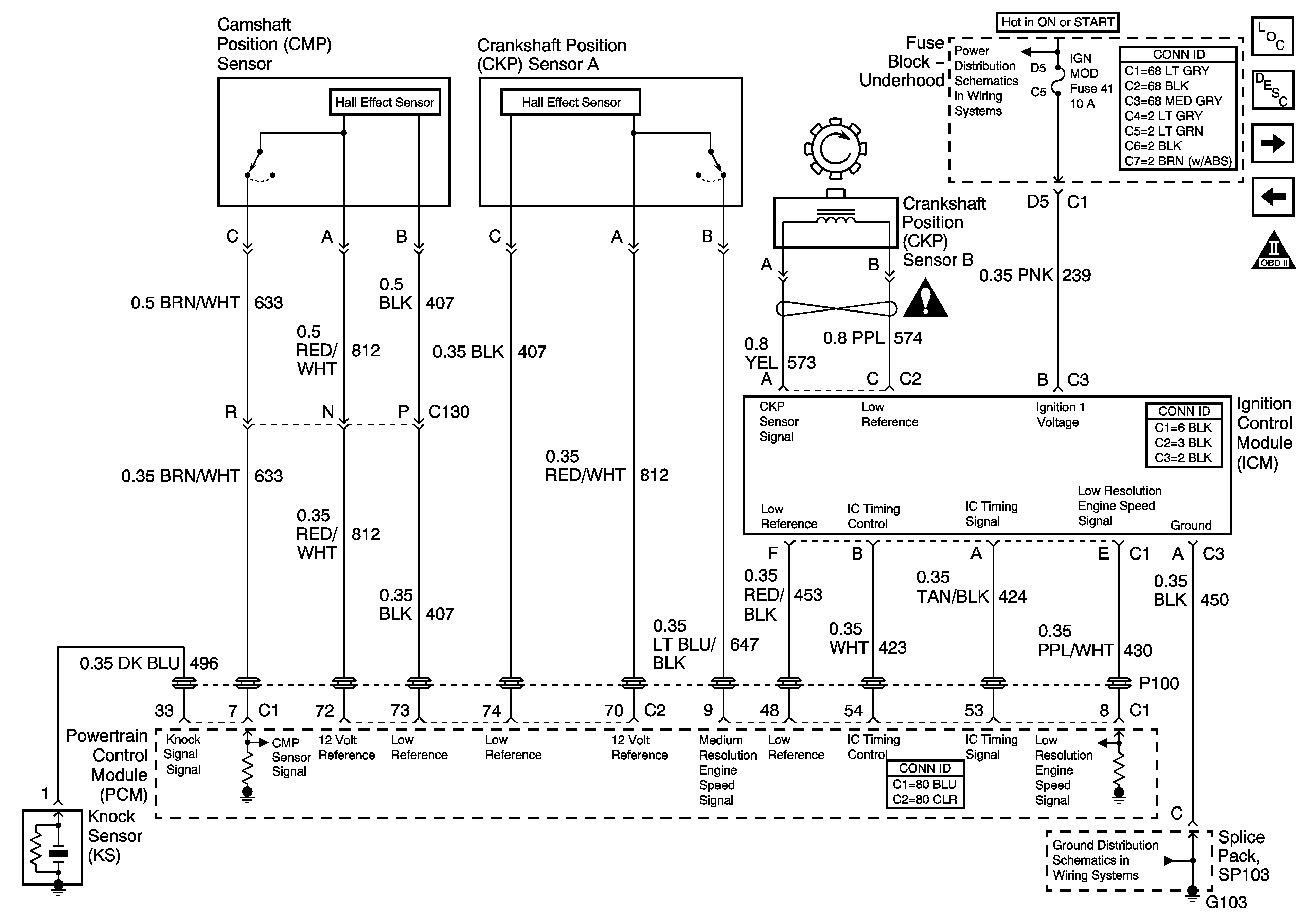
Ignition System
Engine Data Sensors-Pressure and Temperature
Engine Controls Schematic Icons
IGN SW BATT1, ERLS, HTR-A/C and CRANK Fuses
Figure 6:

Ignition System


Object Number: 1391462  Size: FS
Master Electrical Component List
Electronic Ignition (EI) System Description
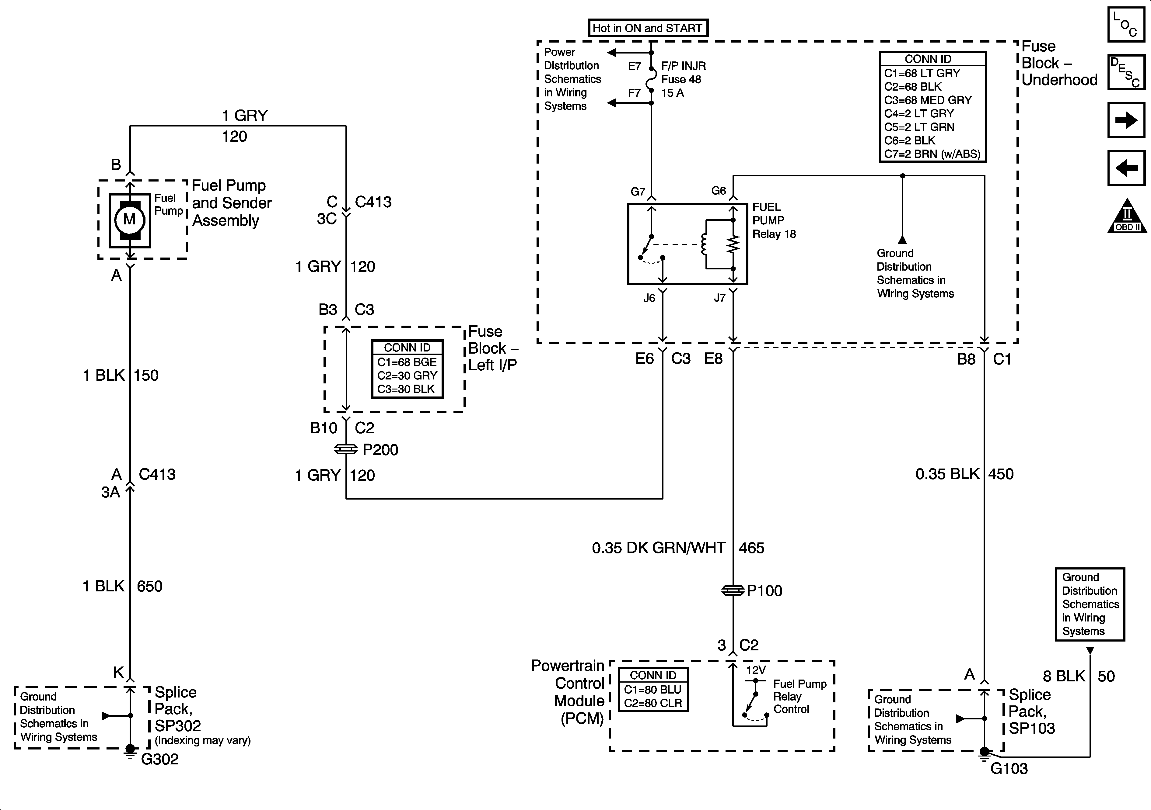
Fuel Pump Controls
Heated Oxygen Sensors
Engine Controls Schematic Icons
IGN SW-BATT2, WIPER, AIR BAG, TURN LPS, IGN MOD, B/U LP/BTSI, PCM IGN, F/P INJR, A/C BFC, AUTO TRANS, ABS/EVO/IGN Fuses
Engine Controls Schematic Icons
G103 and G105
G103 and G105
Figure 7:

Fuel Pump Controls


Object Number: 1391464  Size: FS
Master Electrical Component List
Fuel System Description
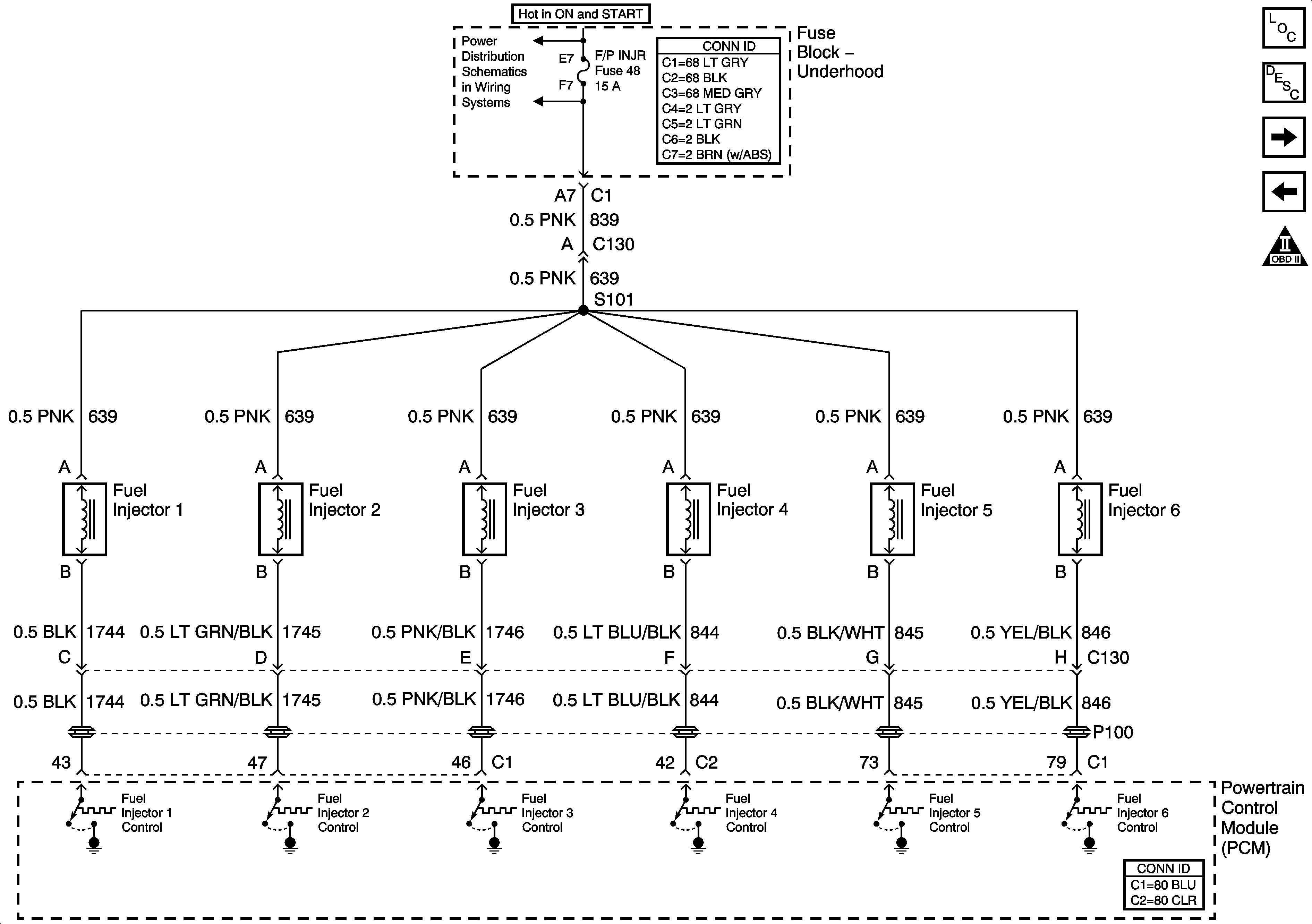
Fuel Injectors
Ignition System
Engine Controls Schematic Icons
IGN SW-BATT2, WIPER, AIR BAG, TURN LPS, IGN MOD, B/U LP/BTSI, PCM IGN, F/P INJR, A/C BFC, AUTO TRANS, ABS/EVO/IGN Fuses
G103 and G105
G302
G103 and G105
G103 and G105
Figure 8:

Fuel Injectors


Object Number: 1391465  Size: FS
Master Electrical Component List
Fuel System Description
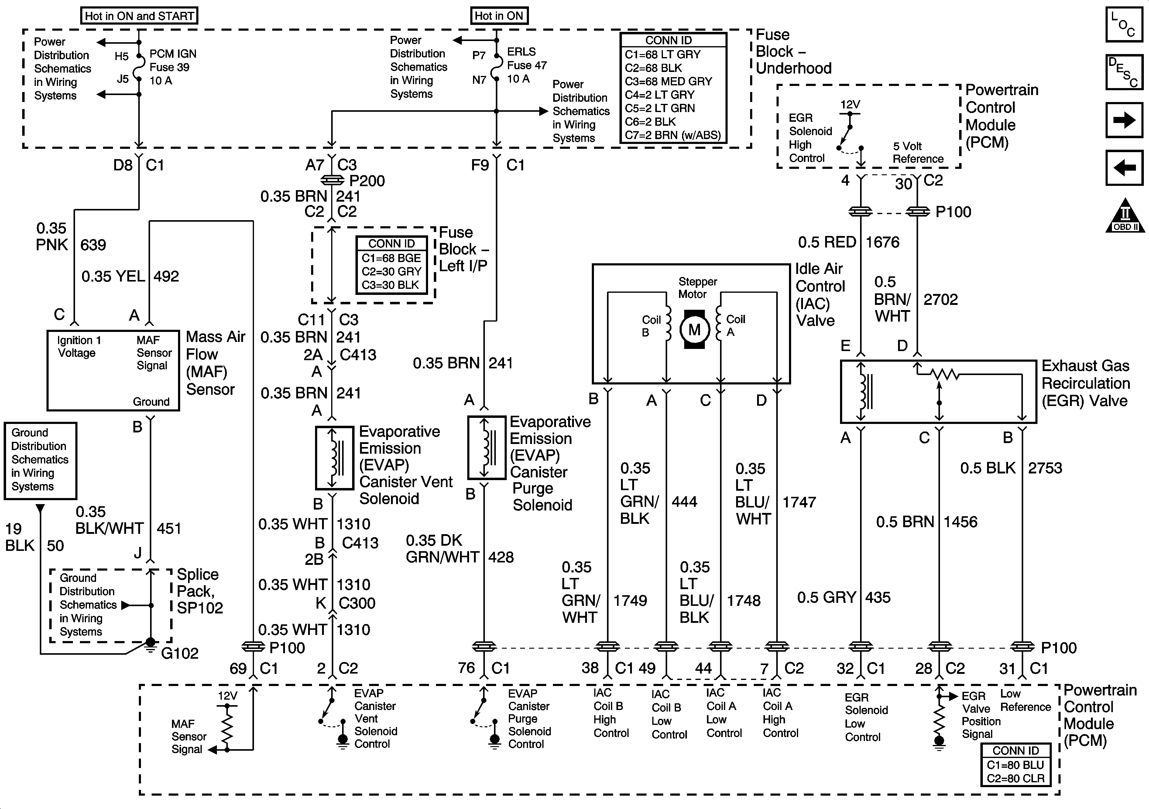
EVAP Controls and EGR
Fuel Pump Controls
Engine Controls Schematic Icons
IGN SW-BATT2, WIPER, AIR BAG, TURN LPS, IGN MOD, B/U LP/BTSI, PCM IGN, F/P INJR, A/C BFC, AUTO TRANS, ABS/EVO/IGN Fuses
Figure 9:

EVAP Controls and EGR


Object Number: 1391466  Size: FS
Master Electrical Component List
Evaporative Emission Control System Description
Controlled/Monitored Subsystem References
Fuel Injectors
Engine Controls Schematic Icons
IGN SW-BATT2, WIPER, AIR BAG, TURN LPS, IGN MOD, B/U LP/BTSI, PCM IGN, F/P INJR, A/C BFC, AUTO TRANS, ABS/EVO/IGN Fuses
IGN SW BATT1, ERLS, HTR-A/C and CRANK Fuses
G102 and G104
G102 and G104
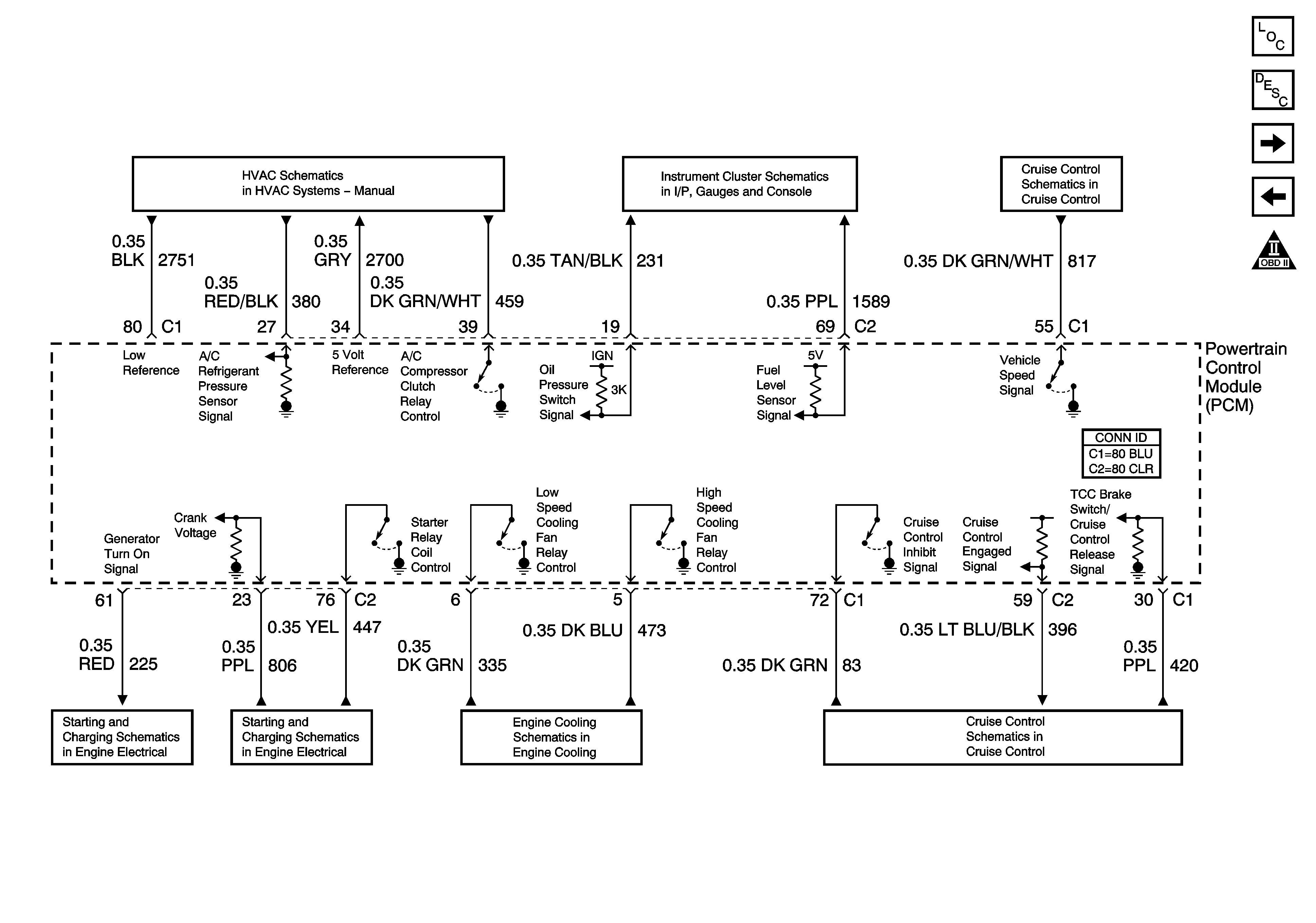
Figure 10:

Controlled/Monitored Subsystem References


Object Number: 1391468  Size: FS
Master Electrical Component List
Powertrain Control Module Description
Transmission Controls References
EVAP Controls and EGR
Engine Controls Schematic Icons
Compressor Controls
Fuel Level and Oil Pressure
Power and Ground
Charging System
Starting System - LA1
Cooling Fans
Power and Ground
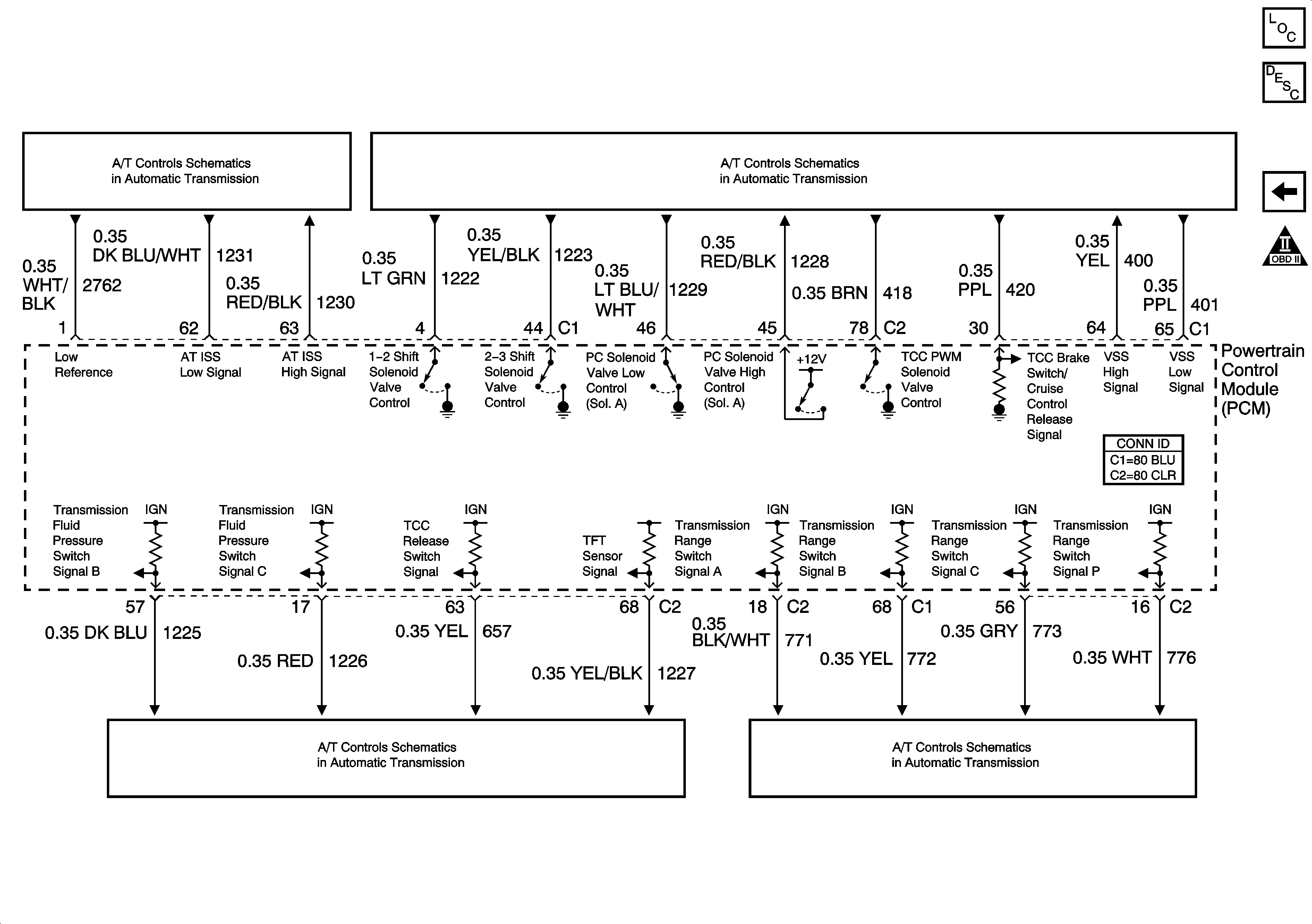
Figure 11:

Transmission Control References


Object Number: 1261636  Size: FS
Master Electrical Component List
Powertrain Control Module Description
Controlled/Monitored Subsystem References
Engine Controls Schematic Icons
Transmission Switches, TFT and A/T ISS Sensor
Transmission Solenoids, VSS and TCC Brake Switch
Transmission Switches, TFT and A/T ISS Sensor
PNP Switch