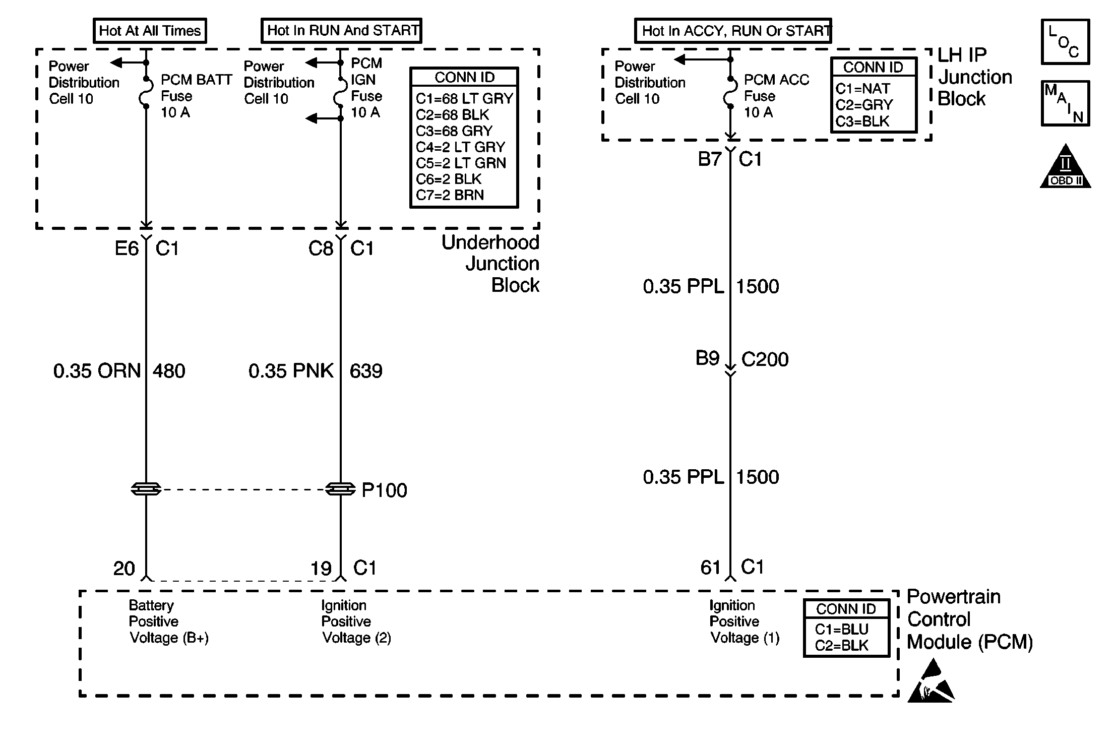
Circuit Description
The Powertrain Control Module (PCM) monitors the ignition voltage on the ignition positive voltage #2 circuit to the Powertrain Control Module (PCM). A DTC will set whenever the voltage is more than a calibrated value.
Conditions for Setting the DTC
The ignition voltage is more than 17 volts.
Action Taken When the DTC Sets
| • | The PCM will record the operating conditions at the time during which the diagnostic fails. This information will store in the Failure Records buffer. |
| • | A history DTC stores. |
| • | All of the outputs will disable. |
| • | The coolant fan turns on. |
Conditions for Clearing the MIL/DTC
| • | A history DTC will clear after 40 consecutive warm up cycles without a fault. |
| • | Use a scan tool to clear the DTCs. |
Diagnostic Aids
| • | Charging the battery with a battery charger and starting the engine can cause this DTC to set. |
| • | If the DTC sets when you operate an accessory, inspect for a poor connection, or test for an excessive current draw. |
| • | Additional DTCs can set as the result of the PCM disabling the outputs. |
Test Description
The number below refers to the step number on the diagnostic table.
Step | Action | Values | Yes | No |
|---|---|---|---|---|
1 | Did you perform the Powertrain On-Board Diagnostic (OBD) System Check? | -- | Go to Step 2 | |
2 |
Is the voltage more than the specified value? | 1,400 RPM 17 V | Go to Step 3 | Go to Diagnostic Aids |
|
Important:: The replacement PCM must be programmed. Refer to Powertrain Control Module Replacement/Programming . Replace the PCM. Refer to Powertrain Control Module Replacement . Did you complete the repair? | -- | Go to Step 4 | -- | |
4 |
Does the DTC reset? | -- | Go to Step 2 | System OK |
