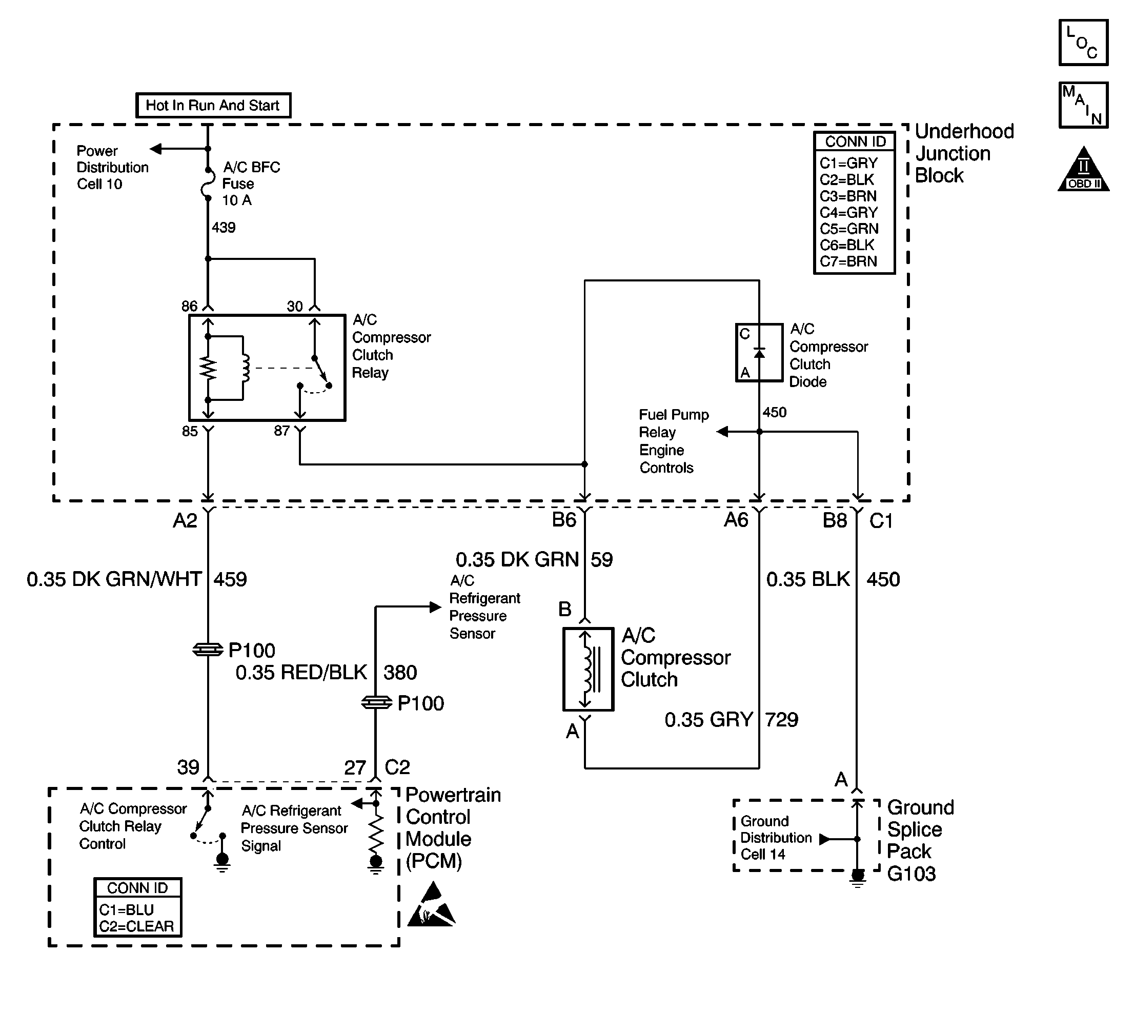
Circuit Description
When A/C is selected through the HVAC controller a signal is supplied to the powertrain control module (PCM) through the Class II serial data circuit. The A/C relay is controlled through the PCM. The PCM monitors the A/C refrigerant pressure. If the A/C refrigerant pressure, and engine operating conditions are within a specific calibrated acceptable ranges the PCM will enable the A/C relay. This is accomplished by providing a ground path for the A/C relay coil within the PCM. When the A/C compressor relay is enabled battery positive voltage is supplied to the compressor clutch coil.
The PCM will enable the A/C compressor clutch whenever the engine is running and the A/C has been requested, unless any of the following conditions are met:
| • | Throttle more than 96 percent |
| • | A/C pressure sensor more than 499 psi (4.99 volts) or less than 35 psi (0.35 volt), as determined by the A/C pressure sensor |
| • | Ignition voltage is below 9.5 volts |
| • | Engine speed is more than 5559 RPM for 3 seconds with the transmission engaged. |
| • | Engine speed is more than 3330 RPM for 3 seconds with the transmission not engaged. |
| • | ECT is more than 140°C (284°F) |
| • | IAT is less than -40°C (-40°F) |
| • | Class II communication error between the HVAC controller and the PCM |
Diagnostic Aids
Inspect for the following conditions:
Many situations may lead to an intermittent condition. Perform each inspection or test as directed.
Important: : Remove any debris from the connector surfaces before servicing a component. Inspect the connector gaskets when diagnosing or replacing a component. Ensure that the gaskets are installed correctly. The gaskets prevent contaminate intrusion.
| • | Loose terminal connection |
| - | Use a corresponding mating terminal to test for proper tension. Refer to Testing for Intermittent Conditions and Poor Connections , and to Connector Repairs in Wiring Systems for diagnosis and repair. |
| - | Inspect the harness connectors for backed out terminals, improper mating, broken locks, improperly formed or damaged terminals, and faulty terminal to wire connection. Refer to Testing for Intermittent Conditions and Poor Connections , and to Connector Repairs in Wiring Systems for diagnosis and repair. |
| • | Damaged harness--Inspect the wiring harness for damage. If the harness inspection does not reveal a problem, observe the display on the scan tool while moving connectors and wiring harnesses related to the sensor. A change in the scan tool display may indicate the location of the fault. Refer to Wiring Repairs in Wiring Systems for diagnosis and repair. |
| • | Inspect the powertrain control module (PCM) and the engine grounds for clean and secure connections. Refer to Wiring Repairs in Wiring Systems for diagnosis and repair. |
If the condition is determined to be intermittent, reviewing the Snapshot or Freeze Frame/Failure Records may be useful in determining when the DTC or condition was identified.
Step | Action | Values | Yes | No | ||||||||
|---|---|---|---|---|---|---|---|---|---|---|---|---|
1 | Did you perform the Powertrain On Board Diagnostic (OBD) System Test? | -- | ||||||||||
2 | Are any PCM or HVAC DTCs stored? | -- | Diagnose applicable DTCs | |||||||||
3 |
Important: The following conditions must be met before continuing with this step:
Is the A/C clutch engaged? | -- | ||||||||||
4 |
Is the A/C clutch engaged? | -- | Go to Diagnostic Aids | |||||||||
5 |
Does the A/C Request display YES? | -- | ||||||||||
6 | Observe the A/C pressure sensor display on the scan tool. Does the A/C pressure sensor indicate a voltage between the specified values? | 0.4V- 4.9V | Go to Cooling Insufficient - Air Conditioning (A/C) System in Heating, Ventilation and Air Conditioning | |||||||||
7 |
Is high side refrigerant pressure within the specified values? | 35-499 psi | Go to Cooling Insufficient - Air Conditioning (A/C) System in Heating, Ventilation and Air Conditioning | Go to DTC P0530 Air Conditioning (A/C) Refrigerant Pressure Sensor Circuit | ||||||||
8 | Inspect the A/C clutch fuse. Is the A/C clutch fuse open? | -- | ||||||||||
9 |
Did you find and correct the condition? | -- | ||||||||||
10 |
Is the A/C clutch engaged? | -- | ||||||||||
11 |
Did you find and correct the condition? | -- | ||||||||||
12 | Test for faulty terminal connections in the A/C relay in the Underhood Accessory Wiring Junction Block. Refer to Testing for Intermittent Conditions and Poor Connections and Wiring Repairs in Wiring Systems. Did you find and correct the condition? | -- | ||||||||||
13 |
Is the A/C clutch engaged? | -- | ||||||||||
14 | Disconnect the A/C clutch connector. Is the A/C clutch engaged? | -- | ||||||||||
15 | Replace the A/C clutch. Refer to Compressor Clutch Plate and Hub Assembly Removal in Heating, Ventilation and Air Conditioning. Did you complete the replacement? | -- | -- | |||||||||
16 | Replace the A/C relay. Refer to Air Conditioning (A/C) Compressor and Cooling Fan Relays Replacement in HVAC. Did you complete the replacement? | -- | -- | |||||||||
17 | Locate and repair the short to voltage in the battery positive feed circuit to the A/C clutch. Refer to Wiring Repairs in Wiring Systems. Did you complete the repair? | -- | -- | |||||||||
18 |
Important: The following conditions must be met before continuing with this step:
Did the A/C clutch engaged and disengage? | -- | System OK |
