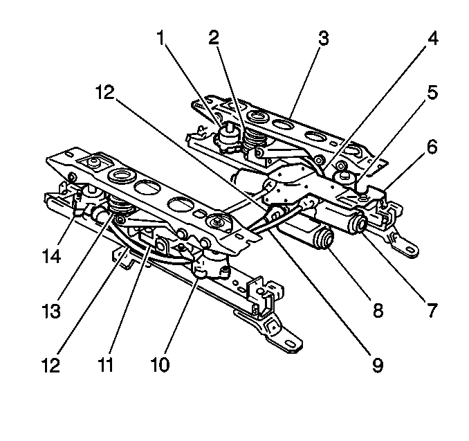
Removal Procedure
- A worm gear drives the jack-screw inside the adjuster. This causes
the seat to move up or down. Ball bearings are used in the actuators in order
to improve durability. Since vertical movement is the most difficult, vertical
assist springs are positioned at the rear of the adjuster assemblies.
Remove the applicable front seat. Refer to
Seat Replacement
.
- Position the front seat on a clean, dry and nonabrasive surface.

- Remove the horizontal and vertical drive
cables (4,9,12).
- Remove the power seat adjuster bolts.
- Remove the power seat adjuster assembly (3).
Important: In order to prevent an ejection of the compressed vertical assist spring,
place the power seat adjuster in the bench vise when you remove the attaching
nut from the rear vertical actuator.
- Remove the attaching nut from the vertical actuator.
- Open the vise slowly in order to relieve the compression on the
vertical assist spring (2).
- Remove the attaching nut from the front vertical actuator.
- In an upward manner, remove the front of the upper channel of
the power seat adjuster.
- Remove the horizontal actuator screws from the upper channel of
the power seat adjuster.
- Remove the front and the rear vertical actuators (1,5,10,14) from
the power seat adjuster (3).
- Remove the horizontal actuators from the power seat adjuster.
Installation Procedure

- Install the horizontal actuators (7,8).
- Fully engage the actuator drive gear with its teeth on the lower
channel rack gear. Verify that the actuator attaching screws are tight. Adjust
the actuator as required in order to remove all free motion between the upper
and the lower channels.
- Using a downward motion, install the front of the upper channel
to the power seat adjuster.
- Install the horizontal actuator screws to the upper channel of
the power seat adjuster (3).
- Install the attaching nut to the front vertical actuator (5).
- Install the vertical assist spring (2). Compress the vertical
assist spring in the vise.
- Install the attaching nut to the rear vertical actuator (1,14).
- Install the power seat adjuster (3).
- Install the power seat adjuster bolts.
- Verify the horizontal travel adjustment.
| 10.1. | Operate the seat control switch until 1 adjuster reaches
a full-forward position. |
| 10.2. | Detach the horizontal drive cable from the adjuster which has
reached its full-forward position. |
| 10.3. | Operate the seat forward until the other adjuster reaches its
full-forward position. |
| 10.4. | Connect the horizontal drive cable and inspect the horizontal
travel of the seat. |
- Verify the front or the rear vertical travel adjustment.
| 11.1. | Operate the seat control switch until one adjuster has reached
the fully raised position at both the front and the rear vertical travel limits. |
| 11.2. | Disconnect both of the front and the rear vertical drive cables
from the fully-raised adjuster. |
| 11.3. | Operate the seat control switch until the other adjuster reaches
the fully-raised position at both the front and the rear vertical travel limits. |
| 11.4. | Connect the previously removed front and rear vertical drive cables
(4,9,12). |
| 11.5. | Verify the vertical travel by operating the adjusters through
1-2 complete cycles. If the adjusters do not appear to be in phase after
the test cycle, repeat this procedure. |
- Install the horizontal and vertical drive cables.
- Install the front and the rear vertical actuator (1,5,10,14) in
order to power the seat adjuster.
- Verify that the adjusters are in phase before installing the front
seat.
- Install the front seat. Refer to
Seat Replacement
.


