SERVICE MANUAL UPDATE-SEC. 8A DIC DIAGNOSIS REVISIONS

VEHICLES AFFECTED: 1987-90 PONTIAC GRAND AM
Some of the service manual section 8A-86 pages have been revised for the Pontiac Grand Am Driver Information Centre, for the model years 1987 through 1990.
The headings on the revised pages in this bulletin indicate the model year(s) which are affected by each revised page.
Please update your 1987 through 1990 Pontiac Grand Am Service Manuals accordingly.
2. Check PNK/WHT and BLK/LT GRN (957) wires and Right Front Door Ajar Switch for a short to ground. If OK replace the DIC Display Module.
3. Check the LT GRN/BLK and BLK/ORN (958) wires and Left Rear Door Ajar Switch for a short to ground. If OK replace the DIC Display Module.
4. Check the BLK/YEL and ORN/BLK (959) wires and Right Rear Door Ajar Switch for a short to ground. If OK replace the DIC Display Module.
5. Check the BLK (150), PPL/WHT and BLK (956) wires and Left Front Door Ajar Switch for an open. If OK replace the DIC Display Module.
6. Check the BLK (150), PNK/WHT and BLK/LT GRN (957) wires and Right Front Door Ajar Switch for an open. If OK replace the DIC Display Module.
7. Check the BLK (150), LT GRN/BLK and BLK/ORN (958) wires and Left Rear Door Ajar Switch for an open. If OK replace the DIC Display Module.
8. Check the BLK (150), BLK/YEL and ORN/BLK (959) wires and Right Rear Door Ajar Switch for an open. If OK replace the DIC Module.
D: TRUNK INPUT TEST
Enter: DIAGNOSTIC MODE (See Opening Procedure)
Conditions:
Trunk: CLOSED
Observe Correct For DIC Display Result Diagnosis ----------- ------ --------- BUS F H See 1
Trunk: OPEN
BUS F L See 2
If all results are correct, replace DIC Display Module.
1. Check the BLK/WHT (158) wire and Trunk Ajar Switch for a short to ground. If OK replace DIC Display Module.
2. Check the BLK/ORN (158) wire and Trunk Ajar Switch for an open. If OK replace the DIC Display Module.
E: HOOD INPUT TEST
Enter: DIAGNOSTIC MODE (Ses Opening Procedure)
Conditions:
Hood:CLOSED
Observe Correct For DIC Display Result Diagnosis ----------- ------ --------- BUS G H See 1
Hood: OPEN
BUS G L See 2
If all results are correct, replace the DIC Display Module.
1. Check the GRY (157) wire and Hood Ajar Switch for a short to ground. If OK replace the DIC Display Module.
2. Check the GRY (157) and BLK (150) wires and Hood Ajar Switch for an open. If OK replace the DIC Display Module.
F: WASHER LEVEL INPUT TEST
Enter: DIAGNOSTIC MODE (See Opening Procedure)
Conditions:
Washer Fluid Level Switch Connector: DISCONNECTED
Observe Correct For DIC Display Result Diagnosis ----------- ------ --------- BUS E H See 1
Washer Fluid Level Switch Connector Terminal B (BLK/WHT): JUMPERED TO GROUND
BUS E L See 2
If all results are correct, check Washer Fluid Level Switch and BLK (150) wire for an open. If OK replace the DIC Display Module.
1. Check BLK/WHT (99) wire for short to ground. If OK replace the DIC Display Module.
2. Check BLK/WHT (99) wire for an open. If OK, replace the DIC Display Module.
G: COOLANT LEVEL INPUT TEST
Enter: DIAGNOSTIC MODE (See Opening Procedure)
Conditions:
Surge Tank Low Coolant Switch Connector: DISCONNECTED
Observe Correct For DIC Display Result Diagnosis ----------- ------ --------- PRT A H See 1
Surge Tank Low Coolant Switch Connector Terminal A (GRY): JUMPERED TO GROUND
PRT A L See 2
If all results are correct check the BLK/ WHT (151) wire for an open. If OK replace the Surge Tank Low Coolant Switch.
1. Check the GRY (69) wires for a short to ground. If OK replace the DIC Display Module.
2. Check the GRY (69) wires for an open. If OK replace the DIC Display Module.
H: FRONT LAMP INPUT TEST
Enter: DIAGNOSTIC MODE (See Opening Procedure)
Conditions:
Lights Monitor Module: DISCONNECTED
Observe Correct For DIC Display Result Diagnosis ----------- ------ --------- BUS A H See 1
Lights Monitor Module Connector Terminal A (PPL): JUMPERED TO GROUND
BUS A L See 2
If all results are correct, check the ORN (40) and BLK/WHT (151) wires at the Lights Monitor Module for power and ground respectively. If OK replace the Lights Monitor Module.
1. Check the PPL (905) wire for a short to ground. If OK replace the DIC Display Module.
2. Check the PPL (905) wire for an open. If OK replace the DIC Display Module.
SYSTEM CHECK TABLE
ACTION NORMAL RESULT FOR DIAGNOSIS
Turn the Ignition Switch to RUN DIC vehicle outline and Do Test A all scrolling segments Do Test B light briefly. If all monitored systems appear normal a single tone sounds, the SYSTEMS OK Indicator lights and PONTIAC scrolls across the display.
Note: Below 10 DEG C (14 DEG F) messages may appear instead of scrolling.
Press the SYSTEM CHECK button Vehicle symbols light along See Symptom for approximately 3 seconds with their corresponding Table messages in the following sequence. 2 Door 4 Door
R DOOR RR DOOR F LAMP RF DOOR L DOOR F LAMP R LAMP LF DOOR COOLANT LR DOOR HOOD R LAMP WASHER COOLANT TRUNK HOOD PONTIAC WASHER TRUNK PONTIAC
One tone will sound. If an error condition(s) exists, each message will be displayed accompanied by four quick tones.
Starting with all doors closed, The appropriate message and Do Test D open each door, one at a time vehicle symbol will be displayed and four quick tones will sound
Open the Trunk and Hood, one The appropriate message Do Test G or F at a time and vehicle symbol will be displayed and four quick tones will sound SYSTEM DIAGNOSIS
Do the tests listed for your symptom in the Symptom Table below, or when directed by the System Check.
Tests follow the Symptom Table.
SYMPTOM FOR DIAGNOSIS
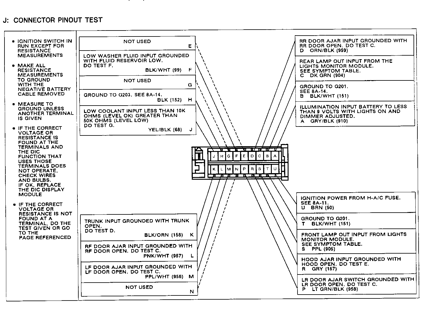
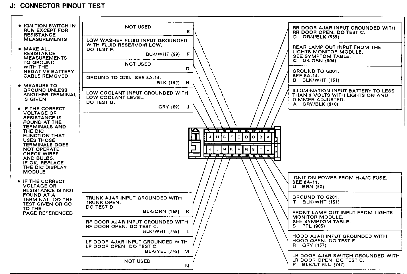
DIC Display Module does not operate Do Test A (also, see Test J terminals U, H and T) DIC Illumination does not work Do Test B (also, see Test J terminals A and B) Hood Ajar Indicator lights with the Do Test E (also, see Test J terminal hood closed R) Hood Ajar Indicator does not light Do Test E (also, see Test J terminal with the hood open R) Trunk Ajar Indicator lights with Do Test D (also, see Test J terminal the Trunk closed R) Trunk Ajar Indicator does not light Do Test D (also, see Test J terminal with the Trunk open K) Door Ajar Indicator lights when Do Test C (also, see Test J the door is closed terminals L, M, D and P) Door Ajar Indicator does not light Do Test C (also, see Test J when the door is open terminals L, M, D and P) Both Headlight and Tail Lamp outages Check ORN/BLK (240) wire for an open. are indicated when both are OK. If OK, replace Lights Monitor Module Headlamp Outage Indicator lights Do Test H (also, see Test J terminal when all lamps are OK S) Tail Lamp Outage Indicator lights Do Test I (also, see Test J terminal when all lamps are OK C) Headlamp Outage Indicator does not Do Test H (also, see Test J terminal light when a lamp is out S) Tail Lamp Outage Indicator does not Do Test I (also, see Test J terminal light when a lamp is out C) Low Washer Fluid Indicator lights Do Test F (also, see Test J terminal when the reservoir is full F) Low Washer Fluid Indicator does not Do Test F (also, see Test J terminal light with the fluid reservoir low F) Low Coolant Indicator does not Do Test G (also, see Test J terminal light with coolant low J) Low Coolant Indicator lights Do Test G (also, see Test J terminal with coolant level OK J)
OPENING PROCEDURE
The following procedure must be performed before the Driver Information Center's on-board diagnostics can be used.
To enter the diagnostic mode do the following:
1. Press and hold the SYS/CHK button on the DIC.
2. Put the Ignition Switch in RUN.
3. After a single tone is heard, release the SYS/CHK button.
The display will now be in the diagnostic mode Pressing the SYS/CHK button allows progressive viewing of the BUS and PRT inputs. These inputs correspond to the various inputs monitored by the DIC.
A: DIC POWER TEST
Measure: VOLTAGE At: DIC DISPLAY MODULE CONNECTOR (Disconnected) Condition: Ignition Switch: RUN
Measure Correct For Between Voltage Diagnosis ------- ------- ---------- U (BRN) Battery See 1 & Ground U (BRN) & Battery See 2 H (BLK) U (BRN) & T Battery See 3 (BLK/WHT)
If all results are correct, replace the DIC.
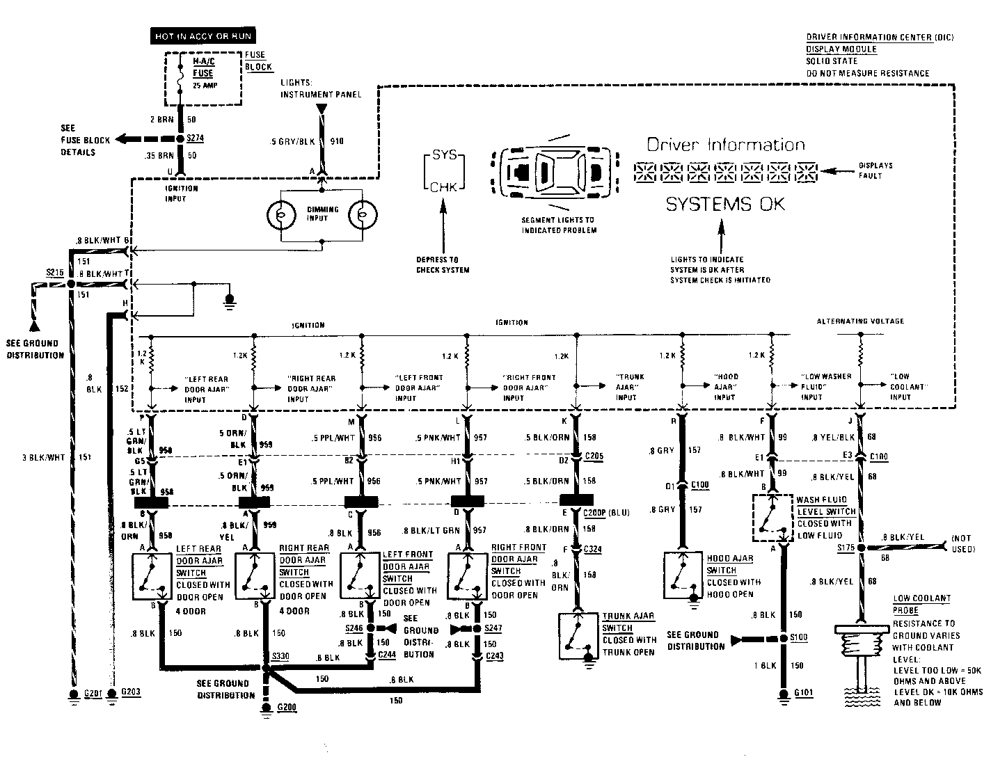
1. Check the BRN (50) wire for an open (see schematic).
2. Check the BLK (152) wire for an open (see schematic).
3. Check the BLK/WHT (151) wire for an open (see schematic).
B: ILLUMINATION TEST
Measurs: VOLTAGE At: DIC DISPLAY MODULE CONNECTOR (Disconnected)
Condition:
Ignition Switch: RUN
Measure Correct For Diagnosis Between Voltage of Incorrect Result ------- ------- ------ A (GRY/BLK) Battery See 1 & Ground
A (GRY/BLK) & B (BLK/ Battery See 2 WHT)
If all results are correct, replace the DIC Display Module.
1. Check the GRY/BLK (910) wire for an open (see 8A-117)
2. Check the BLK/WHT (151) wire for an open (see schematic).
C: DOOR JAMB INPUT TEST
Enter: DIAGNOSTIC MODE (See Opening Procedure)
Condition:
All Doors Closed
Observe Correct For DIC Display Display Diagnosis ----------- ------- ---------
BUS C H See 1
BUS D H See 2
BUS H H See 3
PRT D H See 4
Open LH Front Door
BUS C L See 5
Open RH Front Door
BUS D L See 6
Open LH Rear Door
BUS H L See 7
Open RH Rear Door
PRT D L See 8
If all results are correct, replace the DIC Display Module.
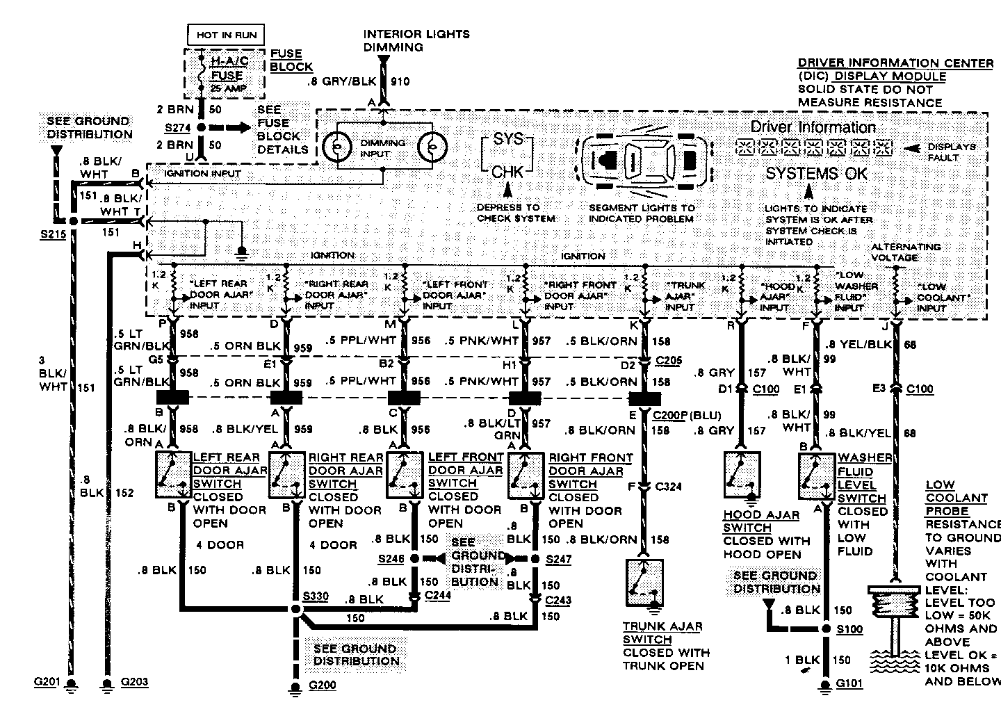
1. Check PPL/WHT and BLK (959) wires and Left Front Door Ajar Switch for a short to ground. If OK replace the DIC Display Module.
2. Check PNK/WHT and BLK/LT GRN (957) wires and Right Front Door Ajar Switch for a short to ground. If OK replace the DIC Display Module.
3. Check the LT GRN/BLK and BLK/ORN (958) wires and Left Rear Door Switch for a short to ground. If OK replace the DIC Display Module.
4. Check the BLK/YEL and ORN/BLK (959) wires and Right Rear Door Ajar Switch for a short to ground. If OK replace the DIC Display Module.
5. Check the BLK (150), PPL/WHT and BLK (956) wires and Left Front Door Ajar Switch for an open. If OK replace the DIC Display Module.
6. Check the BLK (150), PNK/WHT and BLK/LT GRN (957) wires and Right Front Door Ajar Switch for an open. If OK replace the DIC Display Module.
7. Check the BLK (150), LT GRN/BLK and BLK/ORN (958) wires and Left Rear Door Ajar Switch for an open. If OK replace the DIC Display Module.
8. Check the BLK (150), BLK/YEL and ORN/BLK (959) wires and Right Rear Door Ajar Switch for an open. If OK replace the DIC Module.
D: TRUNK INPUT TEST
Enter: DIAGNOSTIC MODE (See Opening Procedure)
Conditions:
Trunk: CLOSED
Observe Correct For DIC Display Result Diagnosis ----------- ------ --------- BUS F H See 1
Trunk: OPEN
BUS F L See 2
If all results are correct, replace DIC Display Module.
1. Check the BLK/WHT (158) wire and Trunk Ajar Switch for a short to ground. If OK replace DIC Display Module.
2. Check the BLK/ORN (158) wire and Trunk Ajar Switch for an open. If OK replace the DIC Display Module.
E: HOOD INPUT TEST
Enter: DIAGNOSTIC MODE (See Opening Procedure)
Conditions:
Hood:CLOSED
Observe Correct For DIC Display Result Diagnosis ----------- ------ ---------- BUS G H See 1
Hood: OPEN
BUS G L See 2
If all results are correct, replace the DIC Display Module.
1. Check the GRY (157) wire and Hood Ajar Switch for a short to ground. If OK replace the DIC Display Module.
2. Check the GRY (157) wire and Hood Ajar Switch for an open. If OK replace the DIC Display Module.
F: WASHER LEVEL INPUT TEST
Enter: DIAGNOSTIC MODE (See Opening Procedure)
Conditions:
Washer Fluid Level Switch Connector: DISCONNECTED
Observe Correct For DIC Display Result Diagnosis ------------ ------ --------- BUS E H See 1
Washer Fluid Level Switch Connector Terminal B (BLK/WHT) JUMPERED TO GROUND
BUS E L See 2
If all results are correct, check Washer Fluid Level Switch and BLK (150) wire for an open. If OK replace the DIC Display Module.
1. Check BLK/WHT (99) wire for short to ground. If OK replace the DIC Display Module.
2. Check BLK/WHT (99) wire for an open. If OK, replace the DIC Display Module.
G: COOLANT LEVEL INPUT TEST
Enter: DIAGNOSTIC MODE (See Opening Procedure)
Conditions:
Low Coolant Probe Connector: DISCONNECTED
Observe Correct For DIC Display Result Diagnosis ------------ ------ --------- PRT A H See 1
Low Coolant Probe Connector: JUMPERED TO GROUND
PRT A L 2
If all results are correct replace the Low Coolant Probe.
1. Check the YEL/BLK and BLK/YEL (68) wires for a short to ground. If OK replace the DIC Display Module.
2. Check the YEL/BLK and BLK/YEL (68) wires for an open. If OK replace the DIC Display Module.
H: FRONT LAMP INPUT TEST
Enter: DIAGNOSTIC MODE (See Opening Procedure)
Conditions:
Lights Monitor Module: DISCONNECTED
Observe Correct For DIC Display Result Diagnosis ----------- ------ --------- BUS A H See 1
Lights Monitor Module Connector Terminal A (PPL): JUMPERED TO GROUND
BUS A L See 2
If all results are correct, check the ORN (40) and BLK/WHT (151) wires at the Lights Monitor Module for power and ground respectively. If OK replace the Lights Monitor Module.
1. Check the PPL (905) wire for a short to ground. If OK replace the DIC Display Module.
2. Check the PPL (905) wire for an open.If OK replace the DIC Display Module.
I: REAR LAMP INPUT TEST Enter: DIAGNOSTIC MODE (See Opening Procedure)
Conditions:
Lights Monitor Module: DISCONNECTED
Observe Correct For DIC Display Result Diagnosis ----------- ------ --------- BUS B H See 1
Lights Monitor Module Connector Terminal M (DK GRN): JUMPERED TO GROUND
BUS B L See 2
If all results are correct, check the ORN (40) and BLK/WHT (151) wires at the Lights Monitor Module for power and ground respectively. If OK replace the Lights Monitor Module.
1. Check the DK GRN (904) wire for a short to ground. If OK replace the DIC Display Module.
2. Check the DK GRN (904) wire for an open. If OK replace the DIC Display Module.
SYMPTOM FOR DIAGNOSIS DIC Display Module does not operate Do Test A (also, see Test J terminals U, H and T) DIC Illumination does not work Do Test B (also, see Test J terminals A and B) Hood Ajar Indicator lights with Do Test E (also, see Test J terminal the hood closed R) Hood Ajar Indicator does not light Do Test E (also, see Test J terminal with the hood open R) Trunk Ajar Indicator lights with Do Test D (also, see Test J terminal the trunk closed R) Trunk Ajar Indicator light with Do Test D (also, see Test J terminal the trunk open K) Door Ajar Indicator lights when Do Test C (also, see Test J terminals the door is closed L, M, D and P) Door Ajar Indicator does not light Do Test C (also, see Test J terminals when the door is open L, M, D and P) Both Headlight and Tail Lamp outages Check ORN (240) wire for an open are indicated when both are OK. If OK, replace Lights Monitor Module Headlamp Outage Indicator lights Do Test H (also, see Test J terminal when all lamps are OK S) Tail Lamp Outage Indicator lights Do Test I (also, see Test J terminal when all lamps are OK C) Headlamp Outage Indicator does not Do Test H (also, see Test J terminal light when a lamp is out S) Tail Lamp Outage Indicator does not Do Test I (also, see Test J terminal light when a lamp is out C) Low Washer Fluid Indicator lights Do Test F (also, see Test J terminal when the reservoir is full F) Low Washer Fluid Indicator does not Do Test F (also, see Test J terminal light with the fluid reservoir low F) Low Coolant Indicator does not light Do Test G (also, see Test J terminal with coolant low J) Low Coolant Indicator lights with Do Test G (also, see Test J terminal coolant level OK J)
OPENING PROCEDURE
The following procedure must be performed before the Driver Information Center's on-board diagnostics can be used.
To enter the diagnostic mode do the following:
1. Press and hold the SYS/CHK button on the DIC.
2. Put the Ignition Switch in RUN.
3. After a single tone is heard, release the SYS/CHK button.
The display will now be in the diagnostic mode Pressing the SYS/CHK button allows progressive viewing of the BUS and PRT inputs. These inputs correspond to the various inputs monitored by the DIC.
A: DIC POWER TEST
Measure: VOLTAGE At: DIC DISPLAY MODULE CONNECTOR (Disconnected)
Condition:
Ignition Switch: RUN
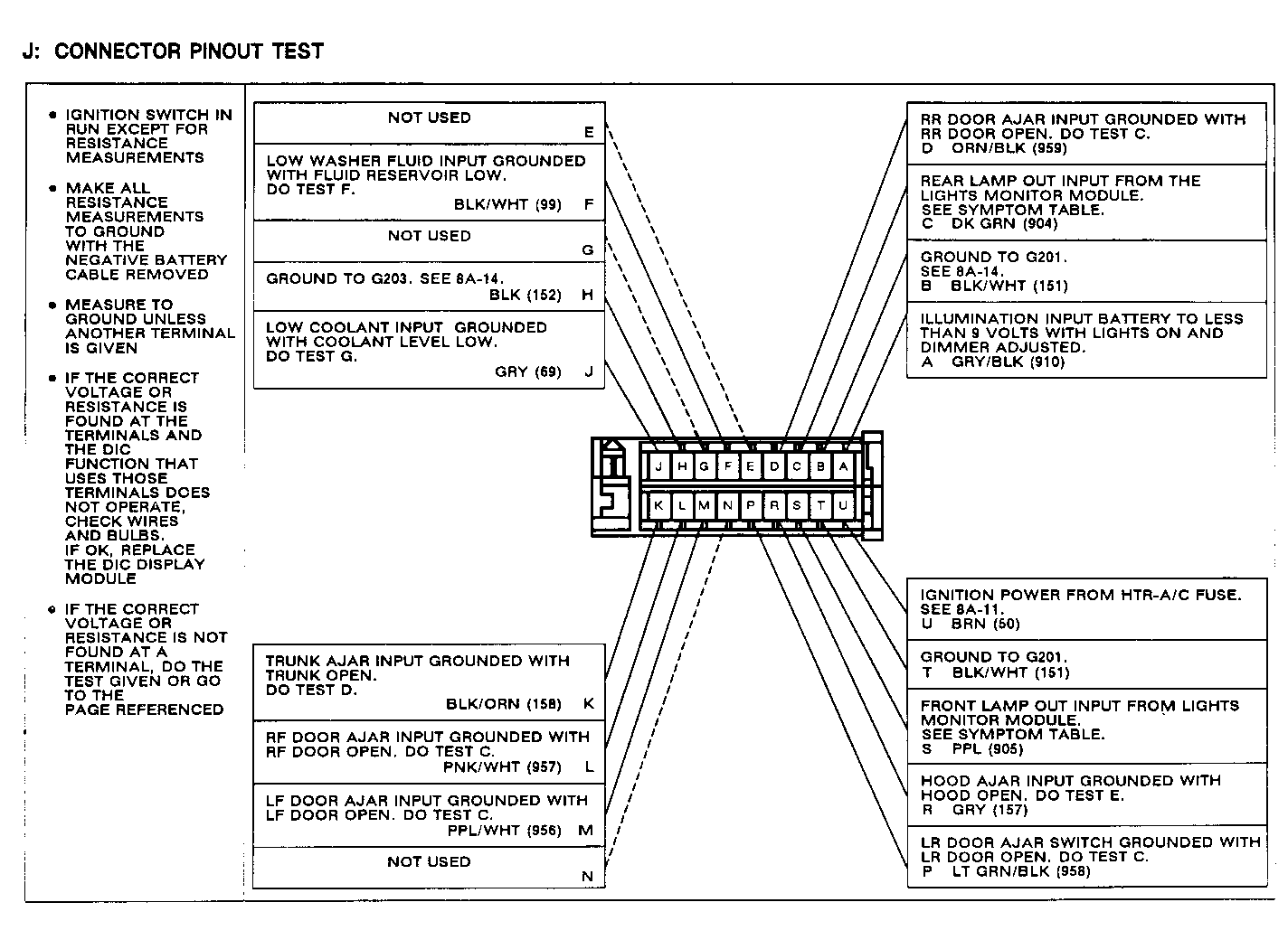
Measure Correct For Between Voltage Diagnosis ------- -------- --------- U (BRN) Battery See 1 & Ground U (BRN) & Battery See 2 H (BLK) U (BRN) & Battery See 3 T (BLK)
If all results are correct, replace the DIC.
1. Check the BRN (50) wire for an open (see schematic).
2. Check the BLK (152) wire for an open (see schematic).
3. Check the BLK (151) wire for an open (see schematic).
B: ILLUMINATION TEST
Measure: VOLTAGE
At: DIC DISPLAY MODULE CONNECTOR (Disconnected)
Condition:
Ignition Switch: RUN
Measure Correct For Diagnosis Between Voltage of Incorrect ------- ------- Result ------ A (WHT) Battery See 1 & Ground
A (WHT) Battery See 2 & B (BLK)
If all results are correct, replace the DIC Display Module.
1. Check the WHT (717) wire for an open (see 8A-117).
2. Check the BLK (151) wire for an open(see schematic).
C: DOOR JAMB INPUT TEST
Enter: DIAGNOSTIC MODE (See Opening Procedure)
Condition:
All Doors Closed
Observe Correct For DIC Display Display Diagnosis ----------- ------- ---------- BUS C H See 1
BUS D H See 2
BUS H H See 3
PRT D H See 4
Open LH Front Door
BUS C L See 5
Open RH Front Door
BUS D L See 6
Open LH Rear Door
BUS H L See 7
Open RH Rear Door
PRT D L See 8
If all results are correct, replace the DIC Display Module.
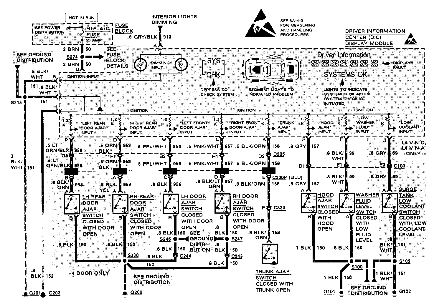
1. Check BLK/YEL (745) wires and Left Front Door Ajar Switch for a short to ground. If OK replace the DIC Display Module.
2. Check the BLK/WHT (746) wires and Right Front Door Ajar Switch for a short to ground. If OK replace the DIC Display Module.
3. Check the BLK/LT BLU (747) wires and Left Rear Door Ajar Switch for a short to ground. If OK replace the DIC Display Module.
4. Check the BLK/LT GRN (748) wires and Right Rear Door Ajar Switch for a short to ground. If OK replace the DIC Display Module.
5. Check the BLK (150) and BLK/YEL (745) wires and Left Front Door Ajar Switch for an open. If OK replace the DIC Display Module.
6. Check the BLK (150) and BLK/WHT (746) wires and Right Front Door Ajar Switch for an open. If OK replace the DIC Display Module.
7. Check the BLK (150) and BLK/LT BLU (747) wires and Left Rear Door Ajar Switch for an open. If OK replace the DIC Module
8. Check the BLK (150) and BLK/LT GRN (748) wires and Right Rear Door Ajar Switch for an open. If OK replace the DIC Module.
D: TRUNK INPUT TEST
Enter: DIAGNOSTIC MODE (See Opening Procedure) Conditions: Trunk: CLOSED
Observe Correct For DIC Display Result Diagnosis ------------ ------ --------- BUS F H See 1
Trunk: OPEN
BUS F L See 2
If all results are correct, replace DIC Display Module.
1. Check the BLK/WHT (158) wire and Ajar Switch for a short to ground. If OK replace DIC Display Module.
2. Check the BLK/ORN (158) wire and Trunk Ajar Switch for an open. Replace the DIC Display Module.
E: HOOD INPUT TEST
Enter: DIAGNOSTIC MODE (See Opening Procedure)
Conditions:
Hood:CLOSED
Observe Correct For DIC Display Result Diagnosis ----------- ------ --------- BUS G H See 1
Hood: OPEN
BUS G L 2
If all results are correct, replace the DIC Display Module.
1. Check the GRY (157) and BLK (150) wires and Hood Ajar Switch for a short to ground. If OK replace the DIC Display Module
2. Check the GRY (157) and BLK (150) wires and Hood Ajar Switch for an open. If OK replace the DIC Display Module.
F: WASHER LEVEL INPUT TEST
Enter: DIAGNOSTIC MODE (See Opening Procedure)
Conditions:
Washer Fluid Level Switch Connector: DISCONNECTED
Observe Correct For DIC Display Result Diagnosis ----------- ------ --------- BUS E H See 1
Washer Fluid Level Switch Connector Terminal B (BLK/WHT): JUMPERED TO GROUND
BUS E L See 2
If all results are correct, check Washer Fluid Level Switch and BLK (150) wire for an open. If OK replace the DIC Display Module.
1. Check BLK/WHT (99) wire for short to ground. If OK replace the DIC Display Module.
2. Check BLK/WHT (99) wire for an open. If OK, replace the DIC Display Module.
G: COOLANT LEVEL INPUT TEST
Enter: DIAGNOSTIC MODE (See Opening Procedure)
Conditions:
Surge Tank Low Coolant Switch Connector: DISCONNECTED
Observe Correct For DIC Display Result Diagnosis ----------- ------- ---------- PRT A H See 1
Surge Tank Low Coolant Switch Connector Terminal A (GRY): JUMPERED TO GROUND
PRT A L See 2
If all results are correct check BLK (150) wire for an open. If OK replace the Surge Tank Low Coolant Switch.
1. Check the GRY (69) wire for a short to ground. If OK replace the DIC Display Module.
2. Check the GRY (69) wire for an open. If OK replace the DIC Display Module.
H: FRONT LAMP INPUT TEST
Enter: DIAGNOSTIC MODE (See Opening Procedure)
Conditions:
Lights Monitor Module: DISCONNECTED
Observe Correct For DIC Display Result Diagnosis ----------- ------ --------- BUS A H See 1
Lights Monitor Module Connector Terminal A (DK BLU/WHT): JUMPERED TO GROUND
BUS A L See 2
If all results are correct, check the ORN (40) and BLK/WHT (151) wires at the Lights Monitor Module for power and ground respectively. If OK replace the Lights Monitor Module.
1. Check the DK BLU/WHT (519) wire for a short to ground. If OK replace the DIC Display Module.
2. Check the DK BLU/WHT (519) wire for an open. If OK replace the DIC Module.
I: REAR LAMP INPUT TEST
Enter: DIAGNOSTIC MODE (See Opening Procedure)
Conditions:
Lights Monitor Module: DISCONNECTED
Observe Correct For DIC Display Result Diagnosis ----------- ------ --------- BUS B H See 1
Lights Monitor Module Connector Terminal M (LT BLU/BLK): JUMPERED TO GROUND
BUS B L See 2
If all results are correct, check the ORN (40) and BLK (151) wires at the Lights Monitor Module for power and ground respectively. If OK replace the Lights Monitor Module.
1. Check the LT BLU/BLK (539) wire for a short to ground. If OK replace the DIC Display Module.
2. Check the LT BLU/BLK (539) wire for an open. If OK replace the DIC Display Module.
General Motors bulletins are intended for use by professional technicians, not a "do-it-yourselfer". They are written to inform those technicians of conditions that may occur on some vehicles, or to provide information that could assist in the proper service of a vehicle. Properly trained technicians have the equipment, tools, safety instructions and know-how to do a job properly and safely. If a condition is described, do not assume that the bulletin applies to your vehicle, or that your vehicle will have that condition. See a General Motors dealer servicing your brand of General Motors vehicle for information on whether your vehicle may benefit from the information.
