QUARTZ SPEEDOMETER BLANKS OUT CRUISE CONTROL INTERMITTENT

VEHICLES AFFECTED: 1985 Oldsmobile Calais
This condition may be caused by poor contact between the printed circuit and printed circuit cluster connectors. This condition may be corrected by providing additional support to the printed circuit using the following procedure.
1. Remove instrument cluster assembly from car.
2. Using double sided tape such as 3M Scotch mount, or equivalent automotive attachment tape (13mm (1/2 in.) wide and 2mm (1/16 in.) thick), cut 4 strips 57mm (2-1/4 in.) long leaving the protective backing on.
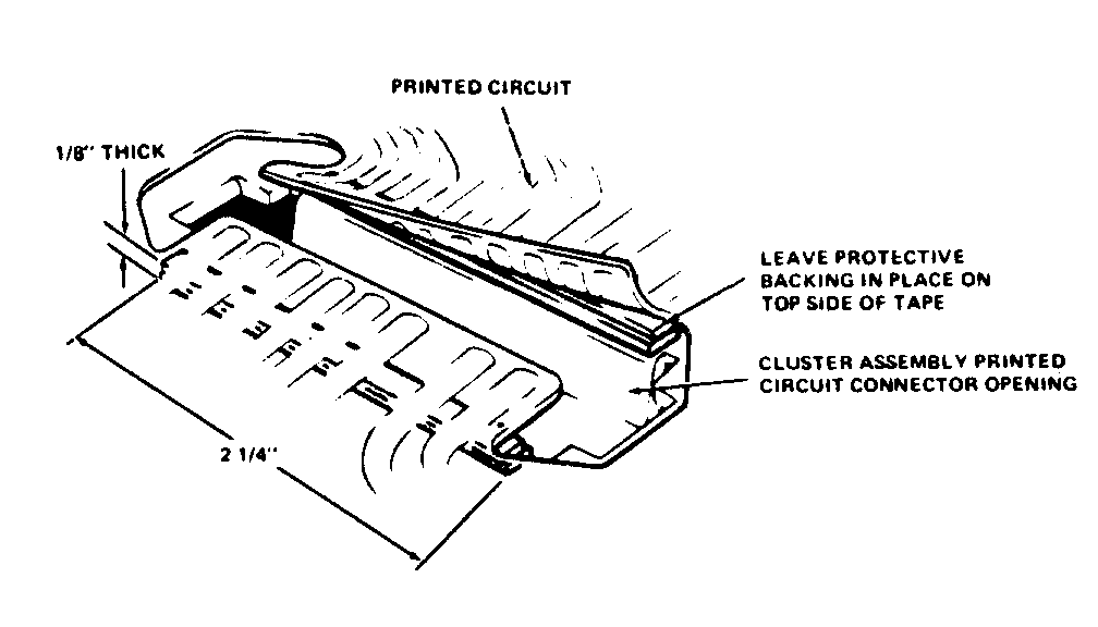
3. Cut each 57mm (2-1/4 in.) strip down the centre and stick the two pieces together. (Each strip should now be 57mm (2-1/4 in.) long, 6mm (1/4 in.) wide, and 3mm (1/8 in.) thick with the protective backing on both top and bottom.
4. Remove the protective backing from one side of 57mm (2-1/4 in.) strip.
5. Remove bulb sockets from cluster as necessary and insert the strip (sticky side toward cluster assembly) between the printed circuit and cluster. Position the tape strip flush with the edge of the cluster connector plug opening and press tape strip down. Leave protective backing in place on the top side of the tape strip. Refer to illustration.
6. Repeat tape strip installation procedure on other edges of cluster connector plug openings.

General Motors bulletins are intended for use by professional technicians, not a "do-it-yourselfer". They are written to inform those technicians of conditions that may occur on some vehicles, or to provide information that could assist in the proper service of a vehicle. Properly trained technicians have the equipment, tools, safety instructions and know-how to do a job properly and safely. If a condition is described, do not assume that the bulletin applies to your vehicle, or that your vehicle will have that condition. See a General Motors dealer servicing your brand of General Motors vehicle for information on whether your vehicle may benefit from the information.
