CAMPAIGN: DOOR PILLAR CRACKS INSTALL INNER/OUTER PLATES

MODELS: 1985-86 CALAIS, GRAND AM, SOMERSET 2 DOOR MODELS
General Motors of Canada has determined that a defect which relates to motor vehicle safety exists in certain 1985 and 1986 Oldsmobile Calais, Grand Am and Somerset two-door models. Small cracks may develop in the body pillar around the door striker bolt hole. If left uncorrected, the cracks would eventually encircle the door strike bolt hole leading to difficulty in closing the door and might allow the door to come open during a vehicle crash which could increase the likelihood of injury to vehicle occupants.
To correct this condition, Dealers are to install an inner and outer reinforcement plate on both left and right body pillars as described in the service procedure of this bulletin.
VEHICLES INVOLVED:
Involved are all 1985 and certain 1986 Calais, Grand Am and Somerset two door models within the following VIN breakpoints:
Year Plant Beginning Up to and Including
CALAIS
1985 Lansing (M) Start of Production End of Production
1985 Lansing (C) Start of Production End of Production
1986 Lansing (M) Start of Production GM301666
1986 Lansing (C) Start of Production GC801230
GRAND AM
1985 FC700001 FC782563
1986 GC500001 GC502900
Year Plant Beginning Up to and Including
SOMERSET
1985 FM400001 FM486086
1986 GM100001 GM102476
All affected vehicles have been identified by the VIN listing provided to involved Dealers with this bulletin. Any Dealer not receiving a listing was not shipped any of the affected vehicles.
DEALER CAMPAIGN RESPONSIBILITY:
Dealers are to service all vehicles subject to this campaign at no charge to owners, regardless of mileage, age of vehicle, or ownership, from this time forward.
Whenever a vehicle subject to this campaign is taken into your new or used vehicle inventory, or it is in your Dealership for service in the future, you should take the steps necessary to be sure the campaign correction has been made before reselling or releasing the vehicle.
Owners of vehicles recently sold from your new vehicle inventory are to be contacted by the Dealer, and arrangements made to make the required modification according to instructions contained in this bulletin.
CAMPAIGN PROCEDURE:
Refer to Section 4 of the Service Policies and Procedures Manual for the detailed procedure on handling Product Campaigns. Dealers are requested to complete the campaign on all transfers as soon as possible.
OWNER NOTIFICATION:
All owners of record at the time of campaign release are shown on the attached computer listing and have been notified by first class mail from General Motors. The listings provided are for campaign activity only and should not be used for any other purp(bse.
PARTS INFORMATION:
Parts required to complete this modification should be ordered through regular channels, as follows:
Description Part Number Quantity Per Vehicle
Repair Package 20716329 1 Body Lock Pillar
2.mm Spacer - Door 4469196 As Required Striker
PARTS AND LABOUR CLAIM INFORMATION:
Credit for the campaign work performed will be paid upon receipt of a properly completed campaign claim card, RAPID terminal or DCS transmission in accordance with the following:
Repair Code Description Time Allowance
2A Install Body Pillar Inner .5 and Outer Reinforcement Left and Righ Sides. Check Striker Bolt Fore/Aft Adjustment and Adjust if Necessary Both Left and Right sides.
3A Same as 2A - one spacer .5
4A Same as 2A - two spacers .5
Time allowance includes 0.1 hour for Dealer administrative detail associated with this campaign. Parts credit will be based on Dealer net plus 30% to cover parts handling.
SERVICE PROCEDURE:
The following service procedure is to be performed on both left and riqht body pillars.
1. Using a number 50 Trox Bit Socket remove the door striker bolt from body pillar.
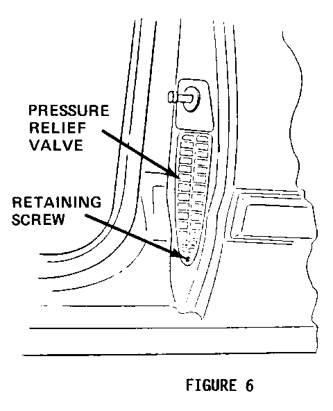
2. Remove screw from pressure relief valve and remove valve from body pillar.
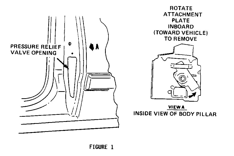
3. Reach through hole exposed by removal of pressure relief valve and remove striker bolt attachment plate by grasping plate and rotating bottom of plate inboard (toward vehicle). Refer to Figure 1.
NOTE: If attachment plate cannot be removed by hand, position a small flat punch through striker bolt hole in body pillar so end of punch contacts the inboard threaded area of plate. Using a hammer, tap the punch to rotate the bottom of the attachment plate inboard.
4. Examine body pillar for cracks in area of striker bolt hole. Clean area and apply touch up paint over any exposed cracks.
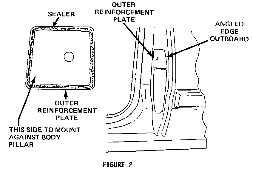
5. Apply a small bead of a medium body sealer such as, 3M 08648 or equivalent, to outside edges of the outer reinforcement plate contained in body pillar reinforcemet kit, Part Number 20716329, and position outer reinforcement plate to body pillar as shown in Figure 2.
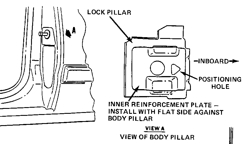
6. Position and hold new inner reinforcement plate in place with flat side against the inside of body pillar with arrowhead shaped hole pointing inboard a s shown in Figure 3. NOTE : Inner reinforcement plates are stamped LH (for left hand use) and RH (for right hand use). Be sure to use the correct plate when installing.
7. Insert striker bolt and thread lock nut contained in body pillar kit onto striker bolt. Hold nut with 17 mm wrench or socket and tighten striker bolt to 53 N.m (40 lbs. ft.).
8. Check striker bolt for proper fore/aft adjustment as follows:
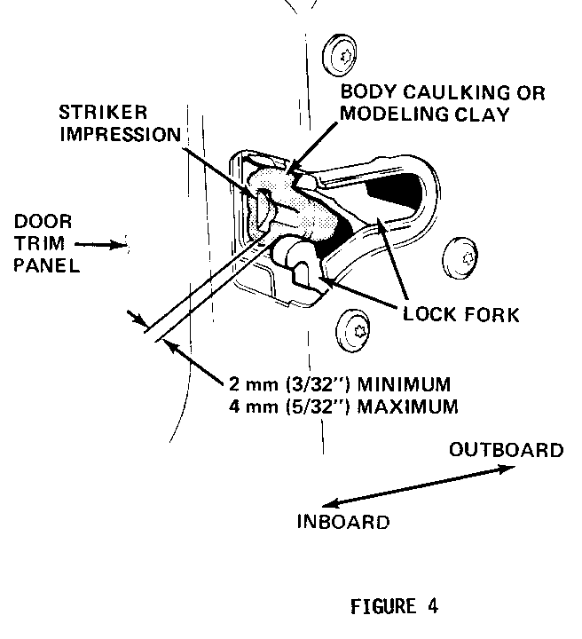
a. Press body caulking such as 3M 08568 into door striker bolt opening as shown in Figure 4.
b. Close door only as far as necessary for striker bolt to form an impression in the caulking. (Complete door closing will make caulking removal difficult.)
c. Striker impression should be centered fore and aft. The minimum allowable measurement for dimension X (Fig. 4) is 2 mm (3/32"). The maximum allowable measurement for dimension X is 4 mm (5/32").
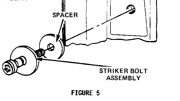
A 1. 5 mm (1/16 ") spacer, Part No . 1260895 or equivalent, can be used to achieve the desired alignment. Refer to Figure 5.
d. Remove all body caulking from door striker bolt opening.
e. If adjustment is necessary remove striker bolt and add or subtract spacers as required. Reinstall striker bolt and torque to 53 N.m (40 lbs. ft.). Refer to Figure 5.
9. Position new pressure relief valve in opening of body pillar. Hold valve upward so top of valve fully contacts top of opening. Using hole at bottom of relief valve, mark and drill a 1/8 inch hole in body pillar for relief valve retaining screw and install screw. Refer to Figure 6.
10. Clean up any excess body sealer around edges reinforcement. of outer
11. Install Campaign Identification Label.
INSTALLATION OF CAMPAIGN IDENTIFICATION LABEL
Clean surface of radiator upper mounting panel and apply a Campaign Identification Label. Make sure the correct campaign number is inserted on the label. This will indicate that the campaign has been completed.

General Motors bulletins are intended for use by professional technicians, not a "do-it-yourselfer". They are written to inform those technicians of conditions that may occur on some vehicles, or to provide information that could assist in the proper service of a vehicle. Properly trained technicians have the equipment, tools, safety instructions and know-how to do a job properly and safely. If a condition is described, do not assume that the bulletin applies to your vehicle, or that your vehicle will have that condition. See a General Motors dealer servicing your brand of General Motors vehicle for information on whether your vehicle may benefit from the information.
