For 1990-2009 cars only
Tools Required
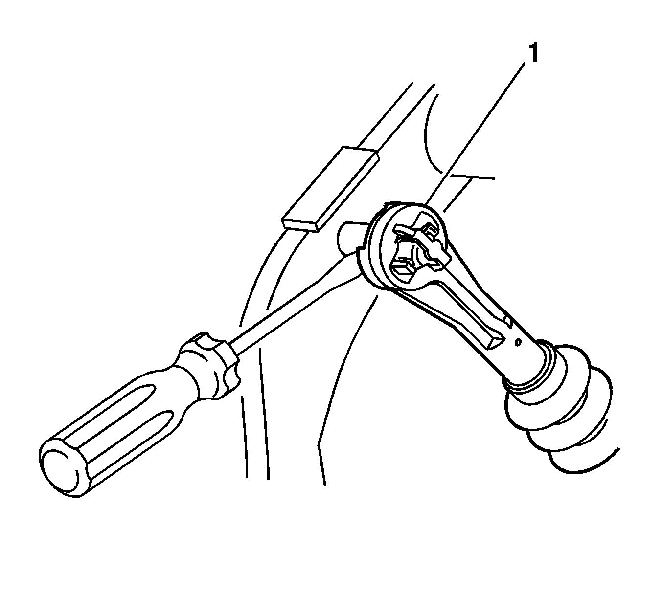
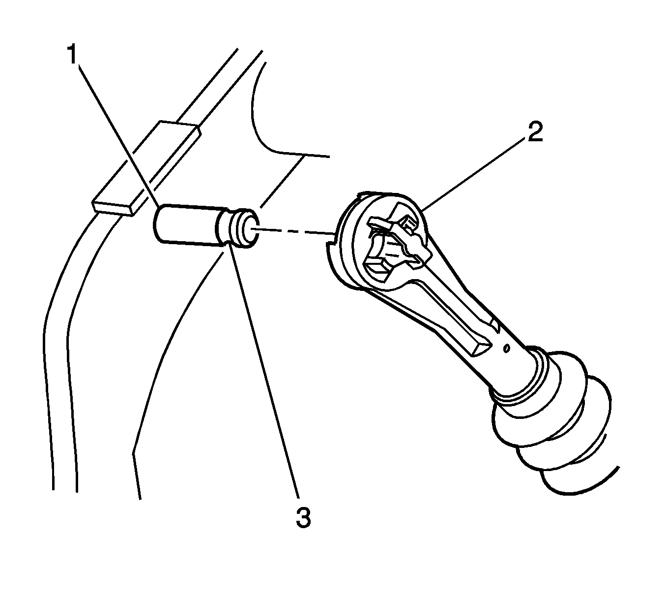
J 36221 Hydraulic Clutch Line Separator
Removal Procedure
- Disable the supplemental inflatable restraints (SIR) system. Refer to SIR Disabling and Enabling in SIR.
- Remove the left instrument panel (I/P) lower insulator panel. Refer to Instrument Panel Insulator Panel Replacement - Left Side in Instrument Panel, Gages and Console.
- Disconnect the clutch master cylinder push rod (1) from the clutch pedal pin.
- Remove the clutch master cylinder reservoir retaining bolt (1).
- Position the clutch master cylinder out of the way.
- Remove the brake booster assembly from the vehicle. Refer to Power Vacuum Brake Booster Replacement in Hydraulic Brakes.
- Disconnect the hydraulic pipe from the clutch master cylinder.
- Cap the hydraulic pipe to prevent contamination to the system.
- Remove the clutch master cylinder retaining nuts.
- Remove the clutch master cylinder and reservoir from the vehicle.


Installation Procedure
- Install the clutch master cylinder and gasket into the opening in front of the dash.
- Install the clutch master cylinder retaining nuts (3).
- Connect the hydraulic pipe to the clutch master cylinder.
- Install the brake vacuum booster. Refer to Power Vacuum Brake Booster Replacement in Hydraulic Brakes.
- Install the clutch master cylinder fluid reservoir and bolt (1) to the brake master cylinder.
- Check the clutch hydraulic reservoir hose for twists or kinks.
- Install the clutch master push rod (1) to the clutch pedal pivot pin.
- Install the left driver side instrument panel insulator. Refer to Instrument Panel Insulator Panel Replacement - Left Side in Instrument Panel, Gages and Console.
- Bleed the clutch hydraulic system. Refer to Hydraulic Clutch Bleeding .

Notice: Refer to Fastener Notice in the Preface section.
Tighten
Tighten the clutch master cylinder nuts (3)
to 25 N·m (18 lb ft).
Tighten
Tighten the clutch master cylinder hydraulic pipe
to 10 N·m (7 lb ft).

Tighten
Tighten the bolt to 10 N·m (7 lb ft).

Important: Ensure the quick connect retaining clips are fully engaged in the groove (1).
