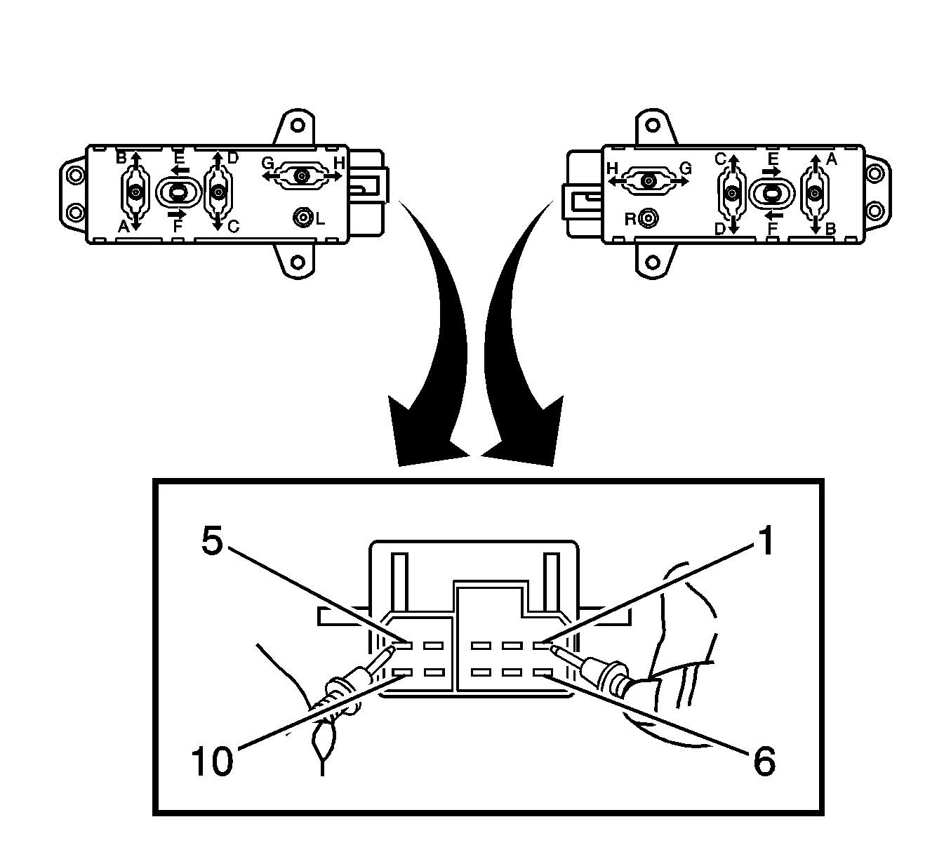
| Table 1: | Power Seat Does Not Recline |
Diagnostic Aids

Seat Adjustment Switch Test | ||
|---|---|---|
Switch Position | Switch Terminals | Value |
Position A | 10 and 5 | Continuity |
Position B | 7 and 5 | Continuity |
Position C | 9 and 5 | Continuity |
Position D | 8 and 5 | Continuity |
Position E | 6 and 5 | Continuity |
Position F | 3 and 5 | Continuity |
Position G | 2 and 5 | Continuity |
Position H | 4 and 5 | Continuity |
Switch in the neutral position | 1 and either 2-4 or 6-10 | Continuity |
Step | Action | Yes | No |
|---|---|---|---|
Schematic Reference: Power Seats Schematics DEFINITION: This test is used by the technician to aid in the diagnosis of the recline function of the seat being inoperative. The test diagnoses the seat adjustment switch and the motor circuits. | |||
1 | Did you perform the Diagnostic System Check-Vehicle? | Go to Step 2 | |
2 |
Does the meter indicate the switch to be normally open? | Go to Step 3 | Go to Step 17 |
3 |
Does the seat switch test good? | Go to Step 4 | Go to Step 8 |
4 |
Does the test lamp illuminate? | Go to Step 7 | Go to Step 5 |
5 |
Does the test lamp illuminate? | Go to Step 11 | Go to Step 6 |
6 |
Does the test lamp illuminate? | Go to Step 16 | Go to Step 13 |
7 |
Does the test lamp illuminate? | Go to Step 15 | Go to Step 8 |
8 |
Does the test lamp illuminate? | Go to Step 12 | Go to Step 9 |
9 |
Does the test lamp illuminate? | Go to Step 16 | Go to Step 14 |
10 | Replace the seat adjustment switch. Refer to Power Seat Switch Replacement . Is the repair complete? | Go to Step 18 | -- |
11 | Repair a fault in the circuit between the positive FORWARD side of the seat recline actuator assembly motor connector and the seat module. Refer to Wiring Repairs in Wiring Systems. Is the repair complete? | Go to Step 18 | -- |
12 | Repair a fault in the circuit between the positive REARWARD side of the seat recline actuator assembly motor and the seat module. Refer to Wiring Repairs in Wiring Systems. Is the repair complete? | Go to Step 18 | -- |
13 | Repair a fault in the circuit between the recline FORWARD output of the seat switch and the recline FORWARD input of the seat module. Refer to Wiring Repairs in Wiring Systems. Is the repair complete? | Go to Step 18 | -- |
14 | Repair a fault in the circuit between the recline REARWARD output of the seat switch and the recline REARWARD input of the seat module. Refer to Wiring Repairs in Wiring Systems. Is the repair complete? | Go to Step 18 | -- |
15 | Replace the seat recline actuator motor assembly. Refer to Seat Adjuster Motor Replacement . Is the repair complete? | Go to Step 18 | -- |
16 | Replace the seat module. Is the repair complete? | Go to Step 18 | -- |
17 | Replace the seat entry position switch. Is the repair complete? | Go to Step 18 | -- |
18 | Operate the system in order to verify the repair. Did you correct the condition? | System OK | Go to Step 3 |
