Disassembly Procedure
- Remove the master cylinder assembly. Refer to Master Cylinder Replacement .
- Ensure the outside of the master cylinder assembly is clean.
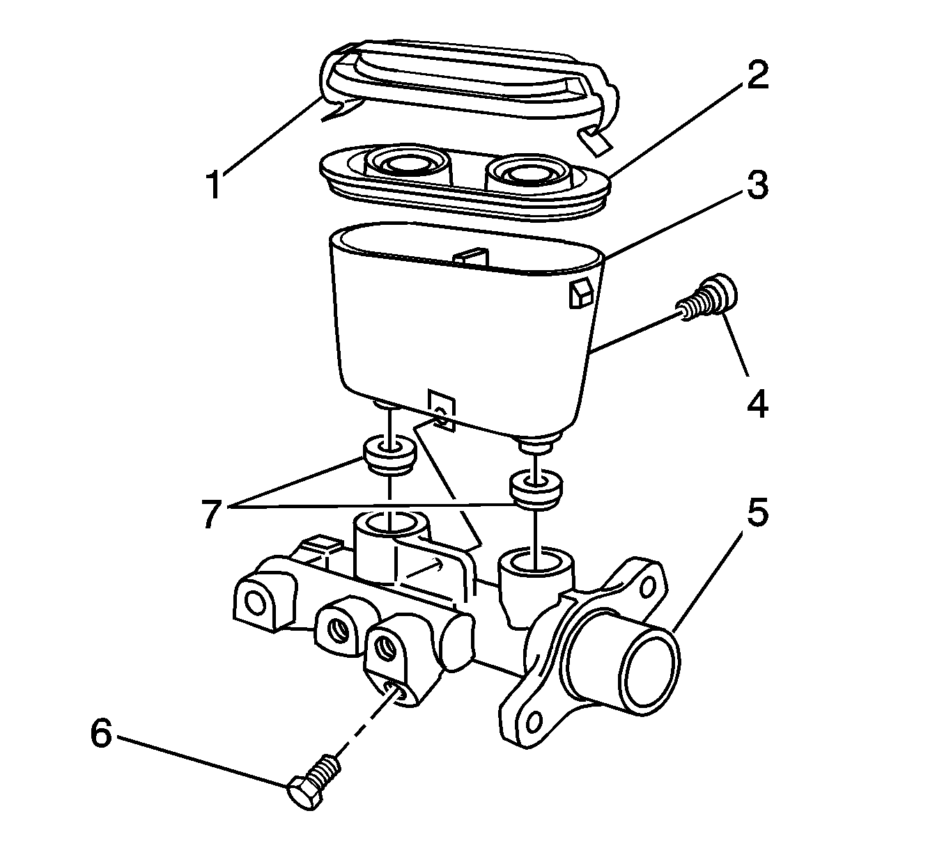
- Remove the screw (4).
- Remove the reservoir (3).
- Remove the 2 grommets (7).
- Remove the blanking plug (6).
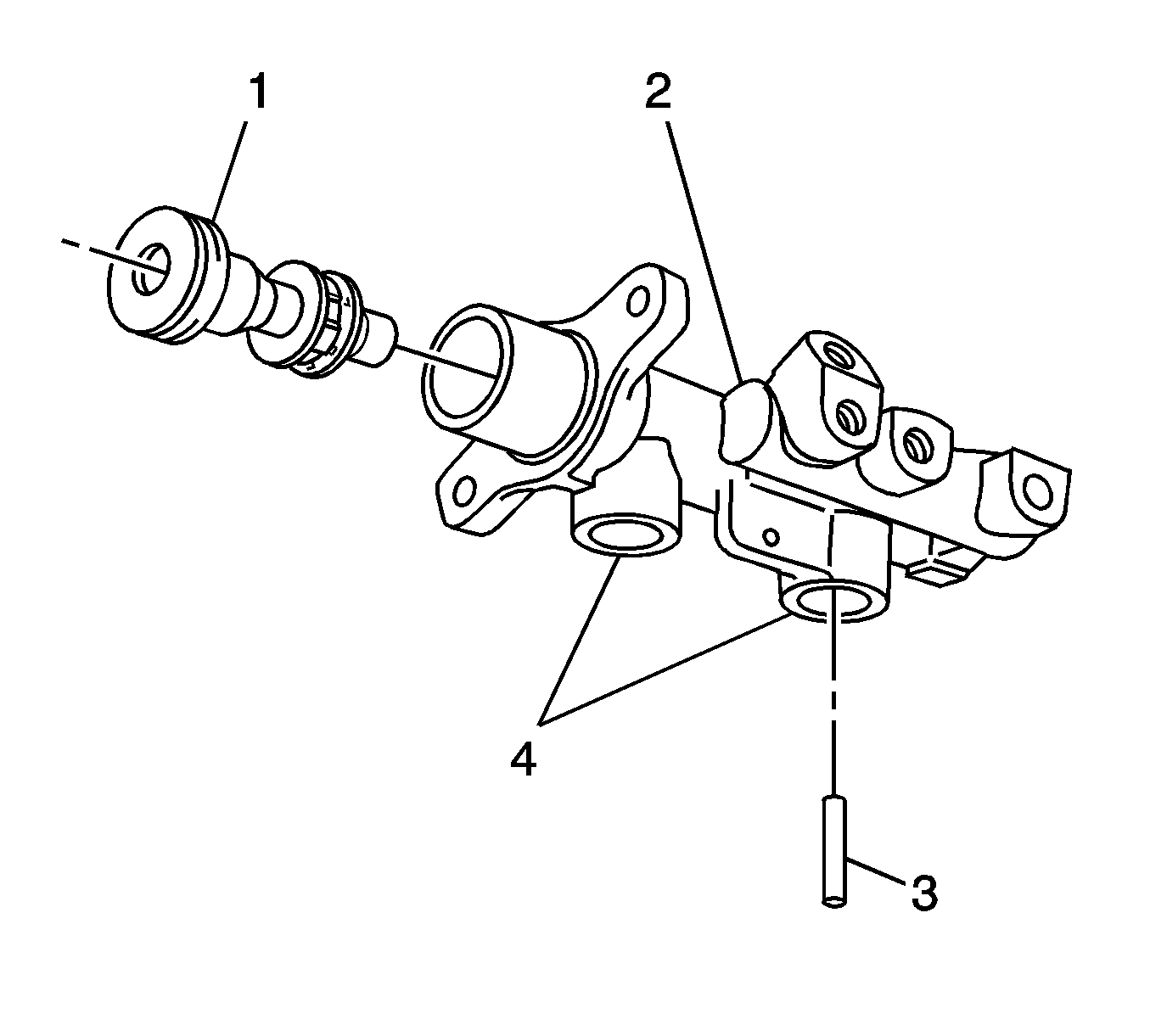
- Hold the master cylinder (2) with the reservoir ports (4) down.
- Push the primary piston (1) with a wood dowel until the piston bottoms in the bore. Allow the secondary piston stop pin (3) to fall out.
- CAREFULLY remove the primary piston from the bore.
- Place 2 blocks of soft wood on a table.
- Place a shop cloth between the 2 blocks of wood.
- Tap the master cylinder flanges on the 2 blocks of wood in order to remove the secondary piston assembly and the return spring (2).
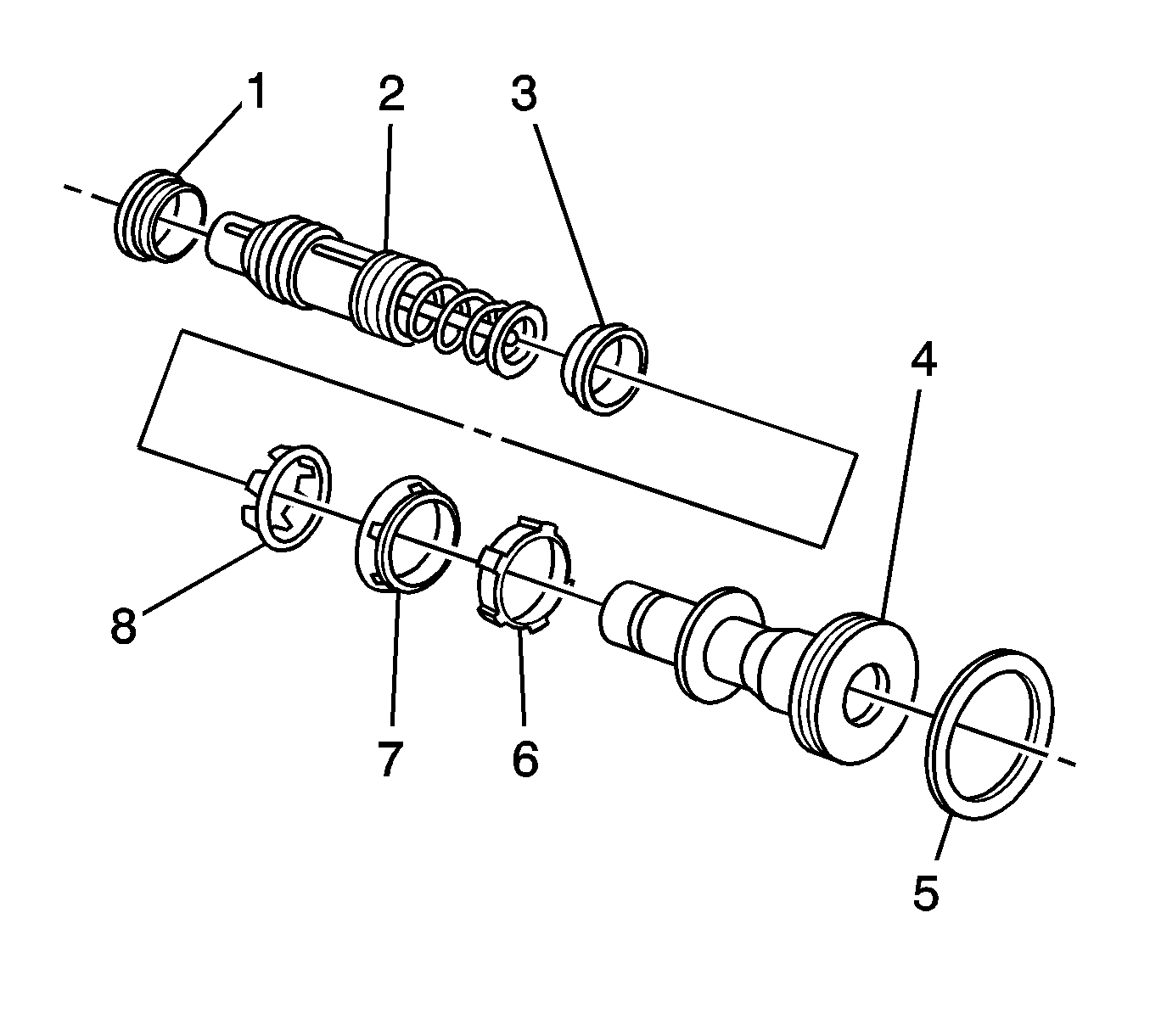
- Use a small flat blade tool in order to CAREFULLY pry apart the legs of the seal retainer (8).
- CAREFULLY remove the seal retainer from the primary piston (4).
- CAREFULLY remove the seal (7).
- CAREFULLY remove the recuperating guide (6).
- CAREFULLY remove the O-ring (5).
- CAREFULLY remove the 2 seals (1) from the secondary piston (2).
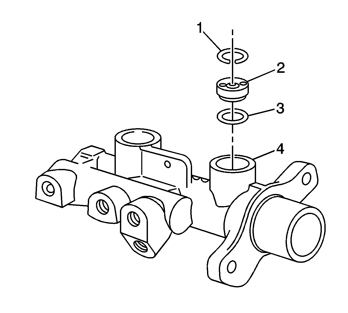
- In the primary port (4), remove the snap ring (1).
- Hold the master cylinder with the reservoir ports down.
- Allow the fast fill valve (2) to fall out. If necessary, tap the master cylinder on a block of soft wood in order to remove the valve.
- Remove the valve O-ring (3).
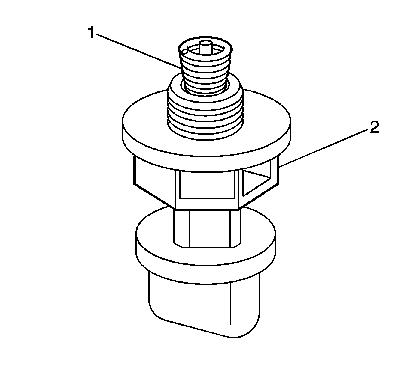
- Remove the brake fluid level differential switch (2) from the master cylinder.
- Ensure the electrical ground spring (1) remains on the switch plunger.
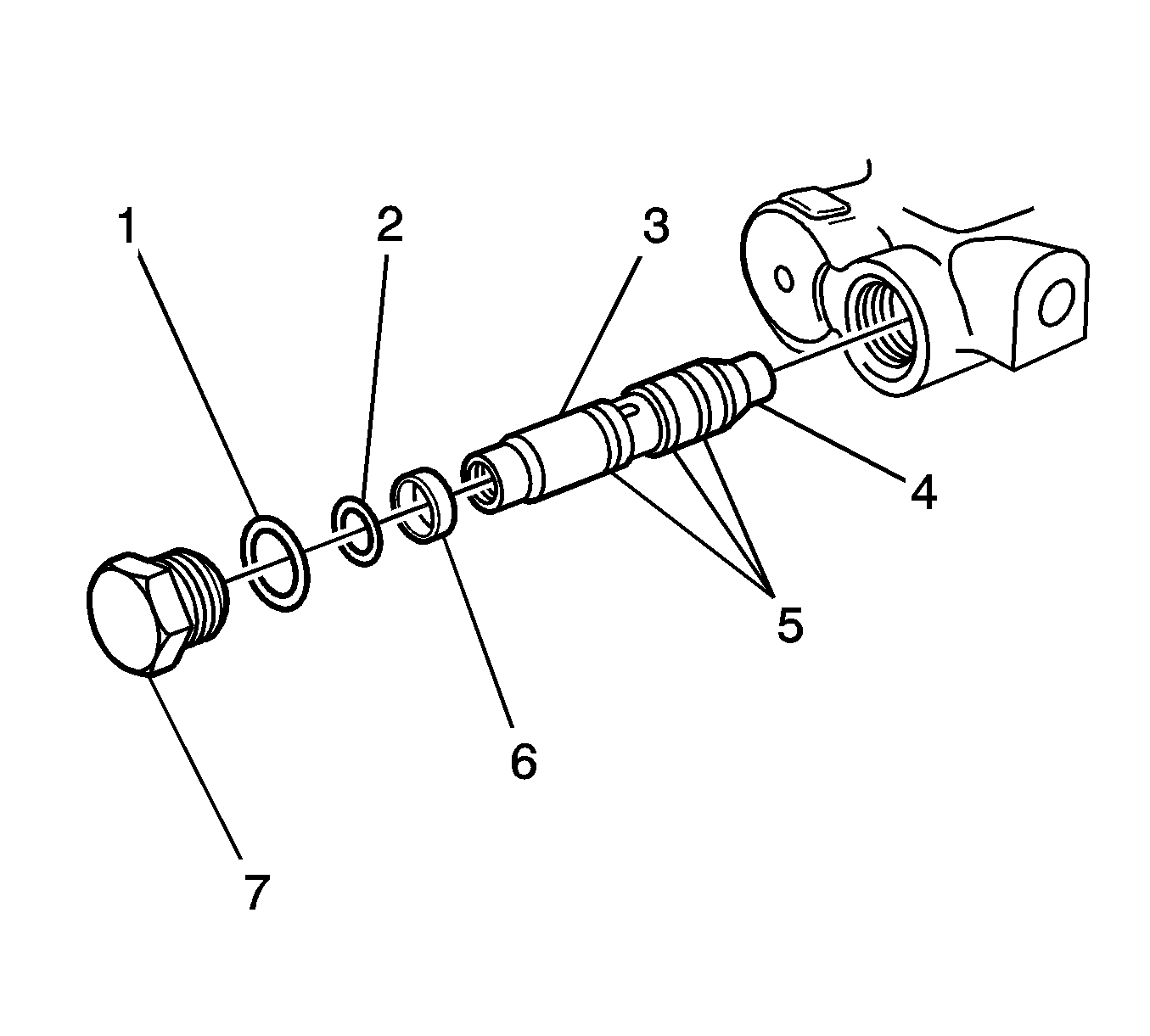
- Remove the end plug (7).
- Tap the master cylinder on a block of soft wood in order to remove the proportioning valve assembly.
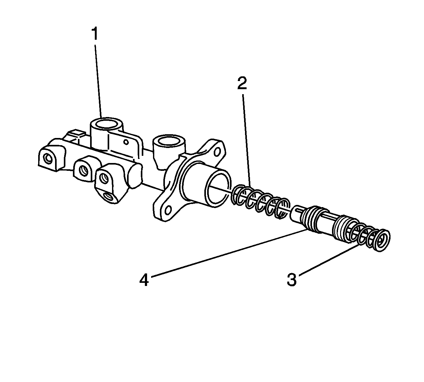
Important: The caged spring (3) and the center valve are part of the secondary piston assembly (4) and not replaceable separately.
Important: The proportioning valve assembly and the seals are part of the master cylinder repair kit.
Cleaning and Inspection Procedure
- Place the master cylinder components on a clean surface.
- Clean the following components with clean methylated spirits:
- Wash the inside of the master cylinder body and all the internal components with GM Vehicle Care® Brake and Clutch Fluid Super DOT-4, GM P/N 88958860, or the equivalent DOT-4 brake fluid.
- Inspect the openings and passages in the components. Ensure the openings are free of foreign matter.
- Inspect the master cylinder bore for scoring or corrosion. Replace a damaged master cylinder.
- Place the primary piston, without seals, into the master cylinder bore. Verify the primary piston moves freely in the large bore of the master cylinder. If the piston does not move freely, replace the master cylinder assembly.

| • | The cap (1) |
| • | The reservoir (3) |
| • | The outside of the master cylinder body (5) |
Notice: Do not hone the master cylinder bore. When the brake master cylinder is overhauled, it is recommended that the cylinder body be replaced rather than CLEANED UP by honing the bore. The master cylinder has a hard, highly polished BEARINGIZED surface, which is produced by diamond boring followed by ball or roller burnishing under heavy pressure. Honing will destroy this hard smooth surface and cause rapid wear of the rubber cups.
Assembly Procedure
- Install the O-ring seal (5) to the groove on the end of the primary piston (4).
- Install the recuperating guide (6) to the primary piston.
- Install the primary seal to the primary piston.
- Install the seal retainer (8) to the primary piston. Use a small flat bladed tool in order to CAREFULLY clip the retaining legs of the retainer into the groove on the primary piston.
- Install the small end of the secondary return spring (2) to the secondary piston (3). This is an interference fit.
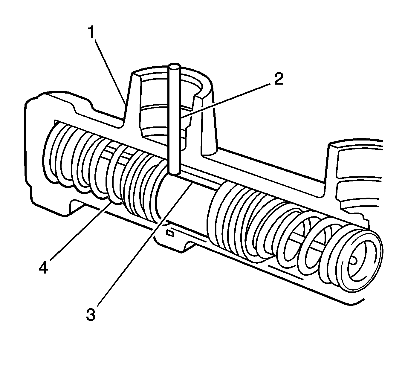
- Align the secondary piston with the master cylinder body. The secondary return spring fits into the forward section of the master cylinder body. The caged spring (3) fits into the rearward section.
- Align the slot in the secondary piston (3) with the reservoir ports (1).
- CAREFULLY install the secondary piston into the smaller bore of the master cylinder body. Ensure the secondary return spring (4) stays on the secondary piston. Ensure the secondary return spring bottoms in the smaller bore.
- Use a soft wood dowel in order to push the secondary piston into the smaller bore. Hold the piston at the bottom of the bore.
- Install the secondary piston stop pin (2) into the larger of the 2 holes in the secondary reservoir port. Install the pin into the slot in the secondary piston. Verify the pin does not protrude more than 6 mm (0.24 in) above the bottom of the secondary reservoir port.
- CAREFULLY install the primary piston into the larger bore of the master cylinder body. Seat the primary piston onto the caged spring.
- Use a soft wood dowel in order to push both pistons into the master cylinder body. Verify the pistons do not stick. Verify the primary piston returns to the end of the bore and is flush with the bore opening.
- Ensure new O-rings (5) are on the proportioning valve (3).
- Ensure the spacer (6) is on the proportioning valve.
- Ensure the O-ring (2) is on the proportioning valve.
- CAREFULLY install the proportioning valve into the bore with the capped end (4) first. Ensure the proportioning valve bottoms in the bore.
- Install the O-ring (1) to the end plug (7).
- Install the end plug to the master cylinder body.
- Ensure the electrical ground spring (1) is seated correctly on the plunger.
- Install the brake fluid level differential switch (2).
- CAREFULLY install the fast fill valve O-ring (3) to the bottom of the primary reservoir port (4).
- Align the fast fill valve (2) with the primary reservoir port. Ensure the rubber base with 6 dimples is facing down.
- Install the fast fill valve into the primary reservoir port.
- Install the snap ring (1) into the primary reservoir port.
- Lubricate the following components with GM Vehicle Care® Brake and Clutch Fluid Super DOT-4, GM P/N 88958860, or the equivalent DOT-4 brake fluid:
- CAREFULLY install the grommets into the bores of the reservoir ports. Seat the grommets on the shoulder of each bore.
- Install the reservoir (3) to the master cylinder.
- Ensure the reservoir screw hole aligns with the master cylinder screw hole.
- Install the screw (4).
- Install the blanking plug (6).
- Fill the reservoir and bleed the master cylinder on the bench. Refer to Master Cylinder Bench Bleeding .
- Install the cap seal to the reservoir.
- Install the cap to the reservoir.
- Install the master cylinder assembly. Refer to Master Cylinder Replacement .

Important: Utilize the master cylinder repair kit in order to replace components in the master cylinder assembly.
Important: The primary seal (7) has 6 shallow grooves around the outer surface. The sealing face of the primary seal must face away from the recuperating guide.


Notice: Refer to Fastener Notice in the Preface section.
Tighten
Tighten the end plug to 28 N·m (21 lb ft).

Tighten
Tighten the switch to 2.0 N·m (17.7 lb in).


| • | The sealing grommets (7) |
| • | The inside of the reservoir ports |
| • | The inside and the top edge of the reservoir (3) |
| • | The underside of the cap seal (2) |
Tighten
Tighten the blanking plug to 14 N·m (10.3 lb ft).
