For 1990-2009 cars only
Tools Required
J 45059 Angle Meter
Removal Procedure
- Raise and support the vehicle. Refer to Lifting and Jacking the Vehicle in General Information.
- Remove the propeller shaft. Refer to Two-Piece Propeller Shaft Replacement .
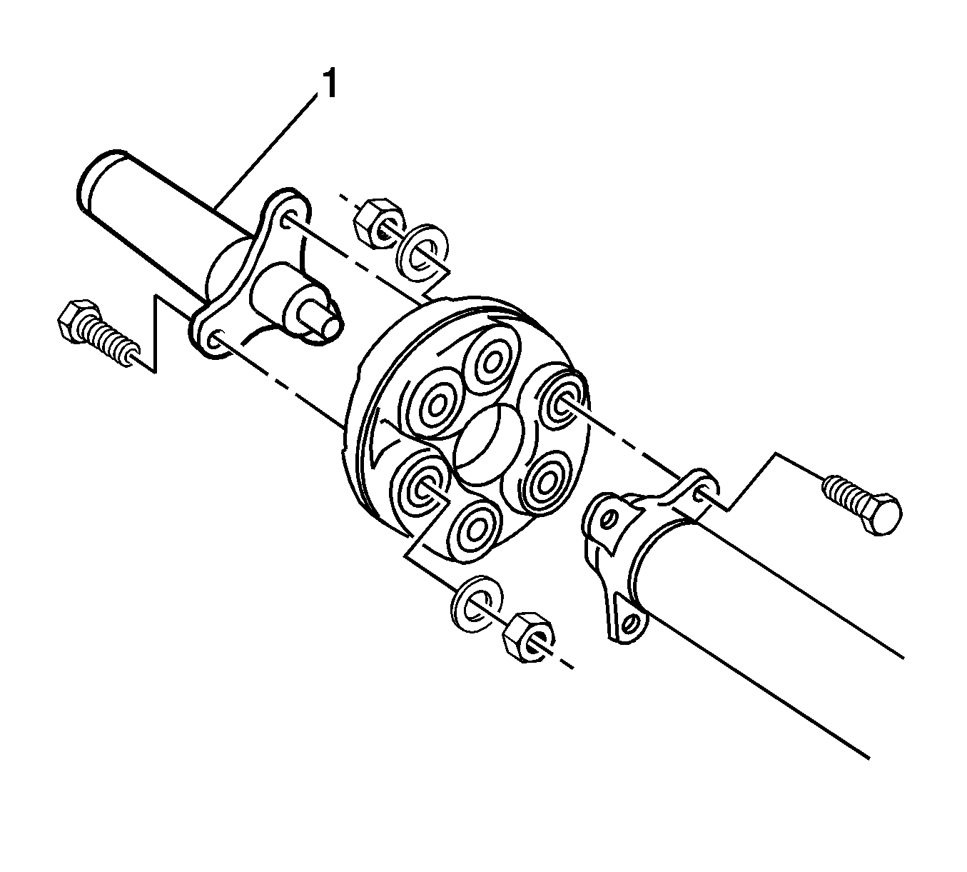
- Remove and discard the propeller shaft sliding yoke (1) bolts, nuts and washers.
- Remove and discard the propeller shaft coupling bolts.

Installation Procedure
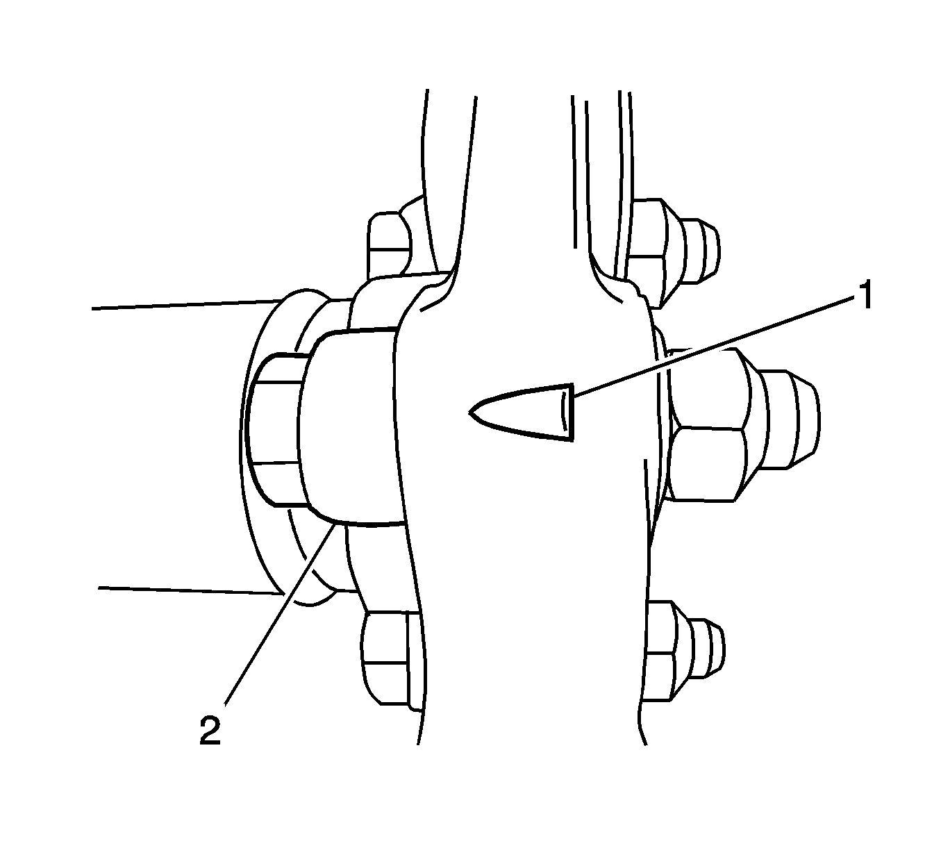
- Align the triangle on the coupling so the point is facing the propeller shaft flange.
- Using new bolts, nuts and washers, install (2) the propeller shaft coupling to the propeller shaft .
- tighten the bolts to 18 N·m (13 lb ft)
- Using angle meter J 45059 tighten the bolts an additional 55 degrees.
- Using new bolts, nuts and washers, install the propeller shaft yoke to the propeller coupling.
- Tighten the bolts to 18 N·m (13 lb ft)
- using angle meter J 45059 tighten the bolts an additional 55 degrees.
- Install the drive shaft. Refer to Two-Piece Propeller Shaft Replacement .
- Lower the vehicle. Refer to Lifting and Jacking the Vehicle in General Information.

Notice: Refer to Fastener Notice in the Preface section.
Tighten
Tighten
