Removal Procedure
- Disconnect the negative battery cable.
- Remove the front suspension support brace. Refer to Front Suspension Support Brace Replacement in Front Suspension.
- Remove the fuel rail cover.
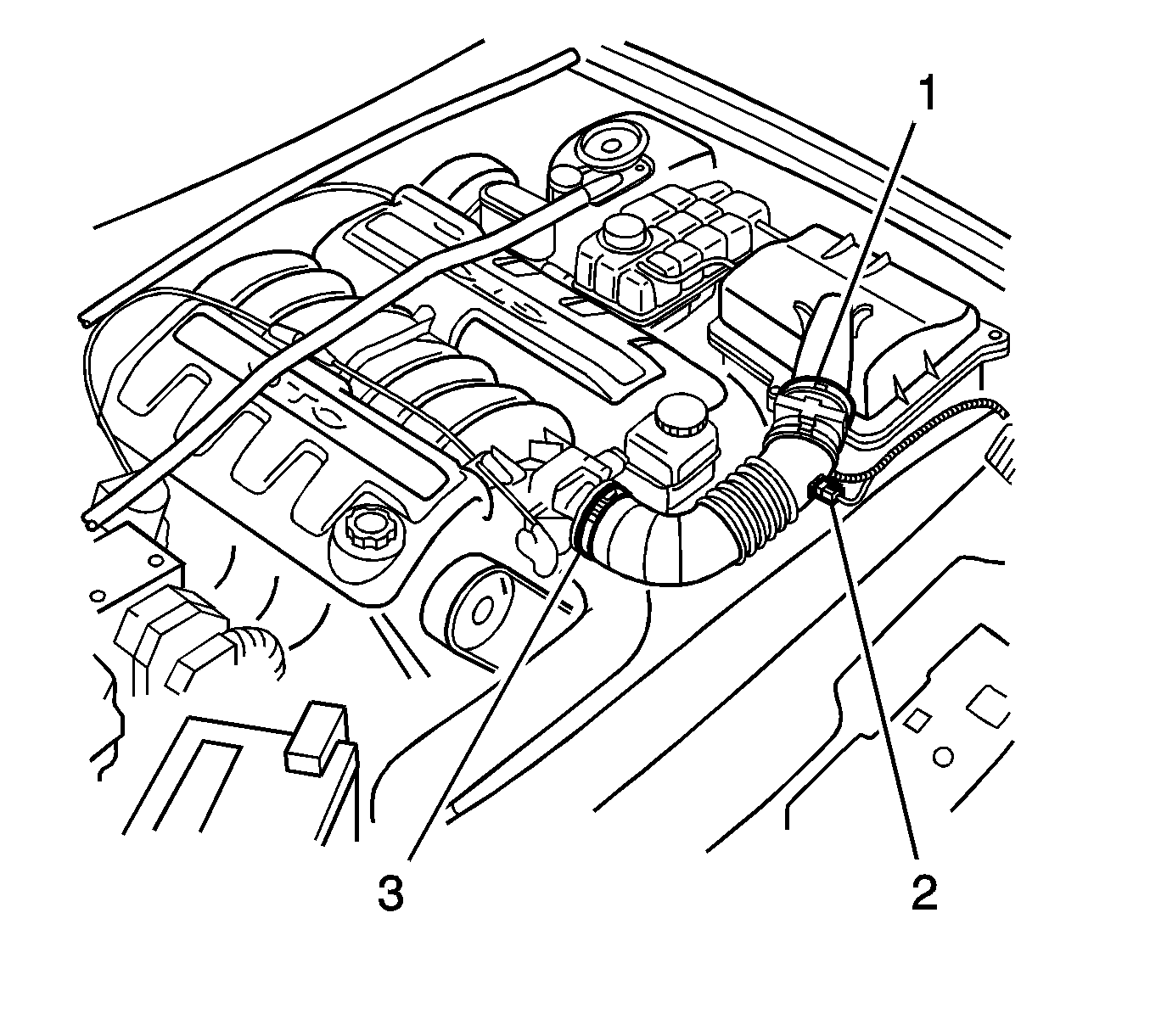
- Lift the locking lever on the mass air flow (MAF) sensor, then disconnect the MAF sensor electrical connector (1).
- Lift the locking lever on the intake air temperature (IAT) sensor, then disconnect the IAT sensor electrical connector (2).
- Loosen 2 intake duct clamps (3), then remove the duct.
- Relieve the fuel pressure. Refer to Fuel Pressure Relief in Engine Controls.
- Remove the oil level indicator and tube. Refer to Oil Level Indicator and Tube Replacement in Engine Mechanical.
- Plug the opening of the oil level indicator tube to prevent entry of foreign matter.
- Raise and support the vehicle. Refer to Lifting and Jacking the Vehicle in General Information.
- Remove the exhaust manifold to exhaust pipe flange nuts.
- Lower the vehicle, then remove the spark plugs. Refer to Spark Plug Replacement in Engine Controls.
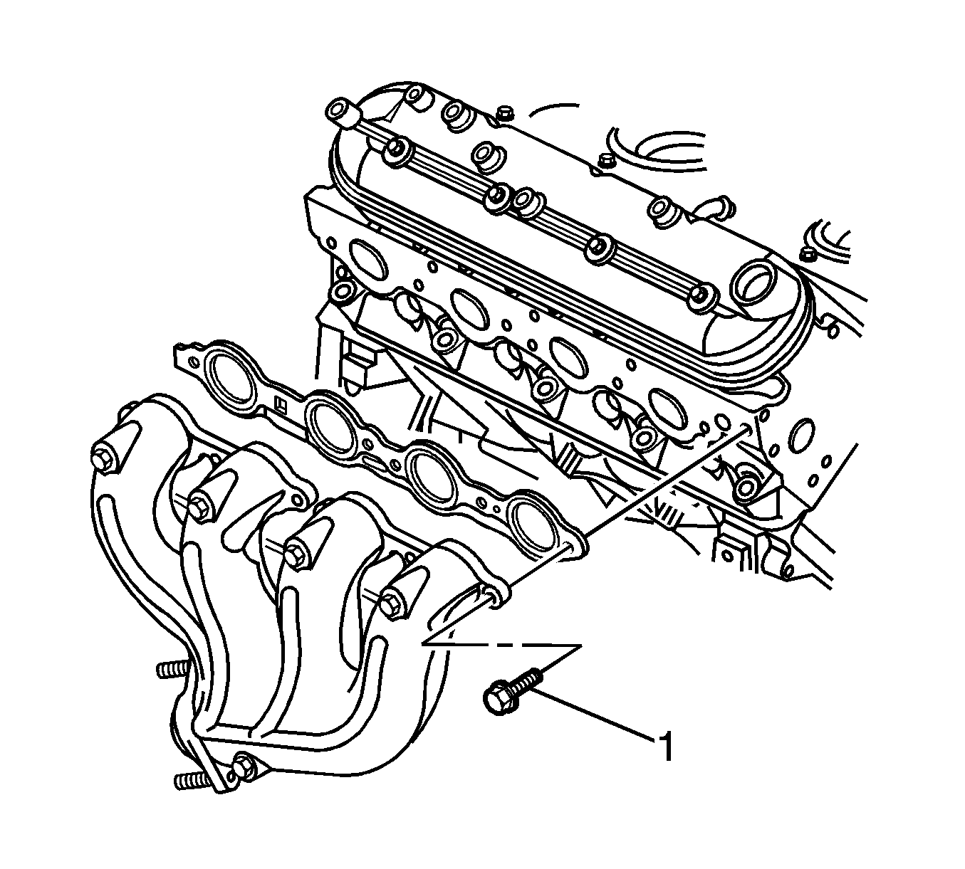
- Progressively loosen, then remove the exhaust manifold bolts (1), working from the outside to center.
- Remove the exhaust manifold and gasket from the cylinder head.
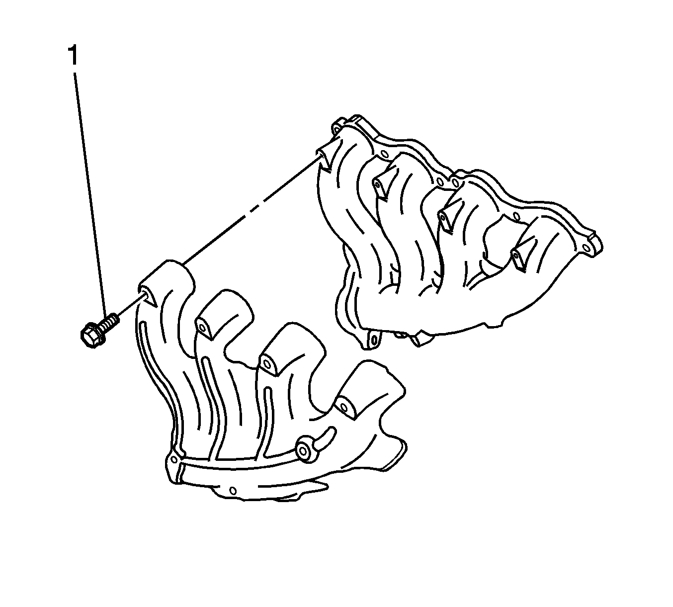
- If equipped, remove the heat shield retaining bolts (1) and the heat shield from the exhaust manifold.
Caution: Refer to Exhaust Service Caution in the Preface section.
Caution: Refer to Battery Disconnect Caution in the Preface section.

Important: Use caution not to damage the oxygen sensors while removing the exhaust manifolds.


Installation Procedure
Important: Tighten the exhaust manifold bolts as specified in the service procedure. Improperly installed and/or leaking exhaust manifold gaskets may effect vehicle emissions and/or On-Board Diagnostics (OBD) II system performance.
The cylinder head exhaust manifold bolt hole threads must be cleaned and free of debris or threadlocking material.- If removed, position the heat shield to the exhaust manifold.
- Install the heat shield to exhaust manifold bolts.
- Position the exhaust manifold and new gasket to the cylinder head.
- Apply a 5 mm (0.2 in) wide band of threadlocker GM P/N 12345493 (Canadian P/N 10953488), or equivalent, to the threads of the exhaust manifold bolts.
- Progressively torque the exhaust manifold bolts from the center to the outsides using 2 steps.
- Tighten the exhaust manifold bolts, first pass to 15 N·m (11 lb ft).
- Tighten the exhaust manifold bolts, second pass to 25 N·m (18 lb ft).
- Bend over the exposed edge of the exhaust manifold gasket at the front of the cylinder head.
- Install the spark plugs. Refer to Spark Plug Replacement in Engine Controls.
- Raise and support the vehicle. Refer to Lifting and Jacking the Vehicle in General Information.
- Install the exhaust manifold to exhaust pipe flange nuts.
- Lower the vehicle.
- Position the intake duct then install 2 intake duct clamps (3).
- Connect the (IAT) sensor electrical connector (2).
- Connect the (MAF) sensor electrical connector (1).
- Install the fuel rail cover.
- Install the front suspension support brace. Refer to Front Suspension Support Brace Replacement in Front Suspension.
- Connect the negative battery cable.
Notice: Refer to Fastener Notice in the Preface section.

Tighten
Tighten the heat shield to the exhaust manifold
bolts to 9 N·m (80 lb in).

Important: Do not apply thread sealant to the first 3 threads of the exhaust manifold bolts.
Tighten
Tighten
Tighten the exhaust manifold to exhaust pipe flange
nuts to 25 N·m (18 lb ft).

Caution: Refer to Exhaust Service Caution in the Preface section.
Caution: Refer to Battery Disconnect Caution in the Preface section.
