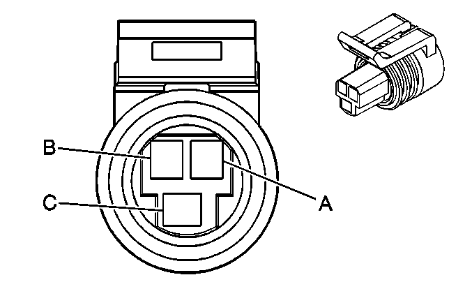
| |||||||
|---|---|---|---|---|---|---|---|
Connector Part Information |
| ||||||
Pin | Wire Color | Circuit No. | Function | ||||
A | GN/OG | 5514 | Low Reference | ||||
B | PU/WH | 2700 | 5-Volt Reference | ||||
C | GN/BK | 380 | A/C Refrigerant Pressure Sensor Signal | ||||
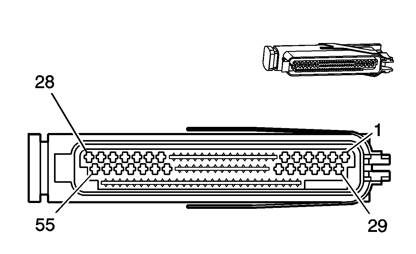
| |||||||
|---|---|---|---|---|---|---|---|
Connector Part Information |
| ||||||
Pin | Wire Color | Circuit No. | Function | ||||
1 | RD | 839 | Ignition 1 Voltage | ||||
2-21 | -- | -- | Not Used | ||||
22 | RD/WH | 560 | Throttle Relaxer Motor - Feed | ||||
23 | -- | -- | Not Used | ||||
24 | RD/YE | 1440 | Battery Positive Voltage | ||||
25 | -- | -- | Not Used | ||||
26 | RD/BK | 561 | Throttle Relaxer Motor - Return | ||||
27 | -- | -- | Not Used | ||||
28 | BK/RD | 450 | Ground | ||||
29-34 | -- | -- | Not Used | ||||
35 | BK/WH | 464 | Delivered Torque Signal | ||||
36 | -- | -- | Not Used | ||||
37 | OG/WH | 463 | Requested Torque Signal | ||||
38-39 | -- | -- | Not Used | ||||
40 | BU | 411 | Throttle Position Signal | ||||
41 | GY | 2701 | 5-Volt Reference | ||||
42 | -- | -- | Not Used | ||||
43 | BK/YE | 2752 | Low Reference | ||||
44-48 | -- | -- | Not Used | ||||
49 | RD/WH | 560 | Throttle Relaxer Motor - Feed | ||||
50 | -- | -- | Not Used | ||||
51 | RD/YE | 1440 | Battery Positive Voltage | ||||
52 | -- | -- | Not Used | ||||
53 | RD/BK | 561 | Throttle Relaxer Motor - Return | ||||
54 | -- | -- | Not Used | ||||
55 | BK/RD | 450 | Ground | ||||
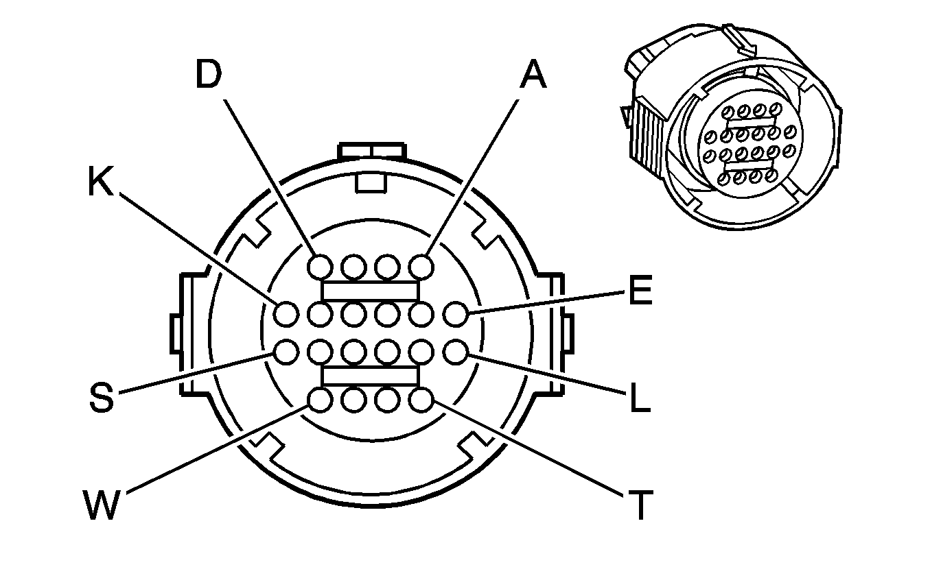
| |||||||
|---|---|---|---|---|---|---|---|
Connector Part Information |
| ||||||
Pin | Wire Color | Circuit No. | Function | ||||
A | L-GN | 1222 | 1-2 Shift Solenoid Valve Control | ||||
B | YE/BK | 1223 | 2-3 Shift Solenoid Valve Control | ||||
C | RD | 1228 | PC Solenoid High Control | ||||
D | GY/BU | 1229 | PC Solenoid Low Control | ||||
E | PK/BU | 339 | Ignition 1 Voltage | ||||
F-K | -- | -- | Not Used | ||||
L | BK/YE | 1227 | TFT Sensor Signal | ||||
M | BK/WH | 2762 | Low Reference | ||||
N | BN/YE | 1224 | Transmission Switch Signal A | ||||
P | GY | 1226 | Transmission Switch Signal C | ||||
R | YE | 1225 | Transmission Switch Signal B | ||||
S | GN/WH | 898 | Shift Solenoid Valve 3 High Control | ||||
T | GY/RD | 422 | TCC Solenoid Valve Control | ||||
U | BN | 418 | TCC PWM Solenoid Valve Control | ||||
V-W | -- | -- | Not Used | ||||
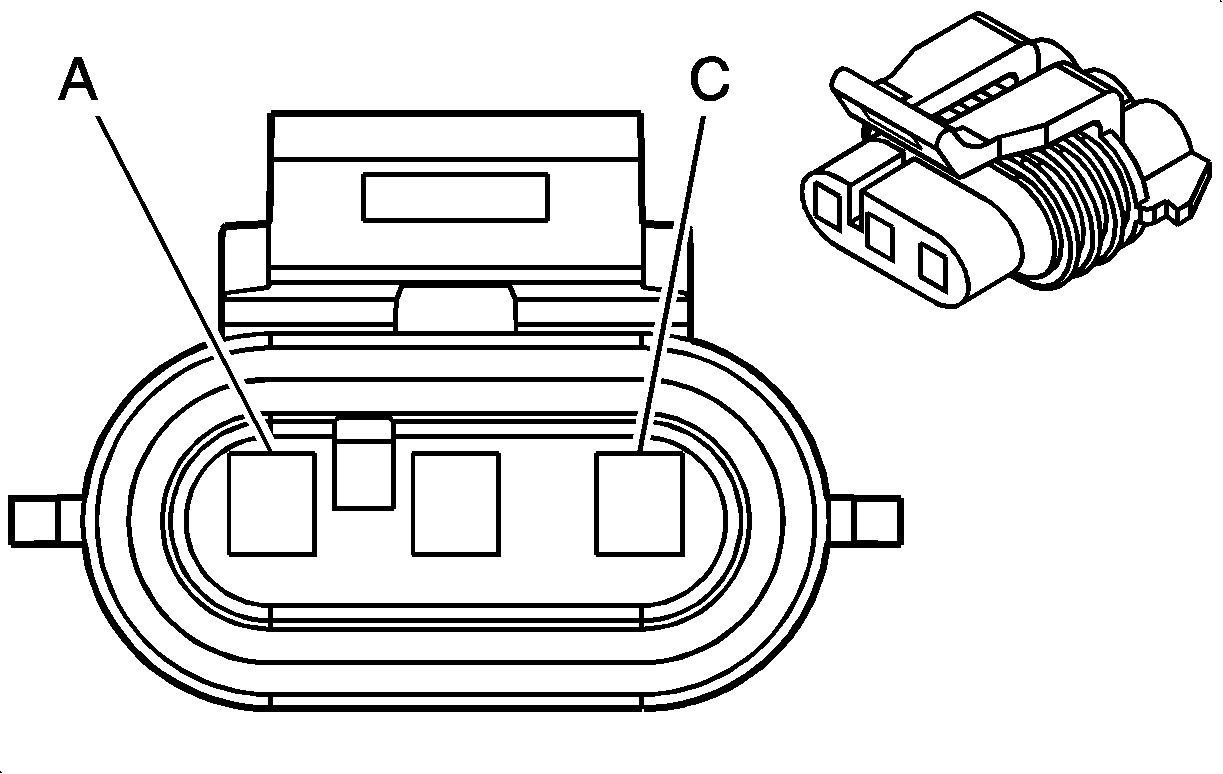
| |||||||
|---|---|---|---|---|---|---|---|
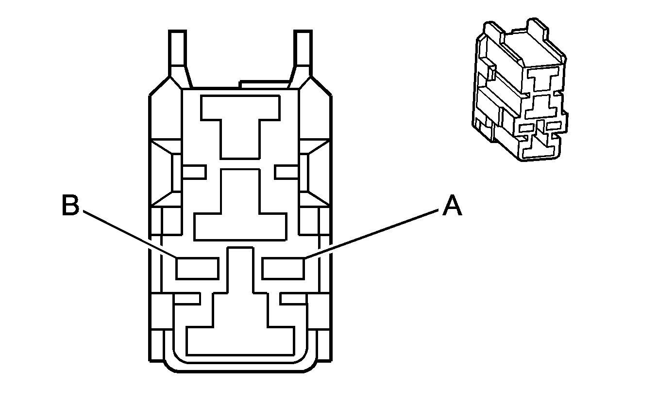
Connector Part Information |
| ||||||
Pin | Wire Color | Circuit No. | Function | ||||
A | BN | 633 | CMP Sensor Signal | ||||
B | RD/WH | 632 | Low Reference | ||||
C | WH/BK | 631 | 12-Volt Reference | ||||
| |||||||
|---|---|---|---|---|---|---|---|
Connector Part Information |
| ||||||
Pin | Wire Color | Circuit No. | Function | ||||
A | GY/BU | 275 | Neutral Safety Switch Signal | ||||
B | GY | 434 | Park Neutral Position Switch Park Signal | ||||

| |||||||
|---|---|---|---|---|---|---|---|
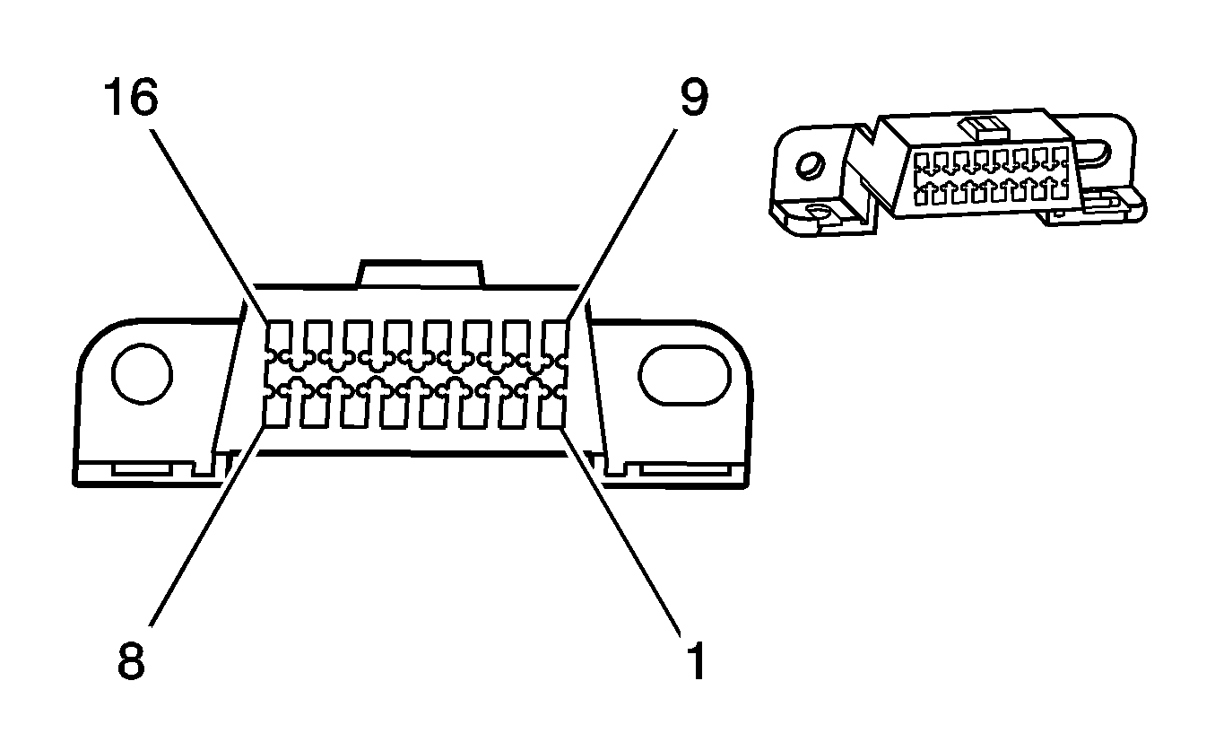
Connector Part Information |
| ||||||
Pin | Wire Color | Circuit No. | Function | ||||
A | L-BU | 573 | CKP Sensor Signal | ||||
B | L-BU/BK | 574 | Low Reference | ||||
C | L-BU/WH | 2867 | 12-Volt Reference | ||||
| |||||||
|---|---|---|---|---|---|---|---|
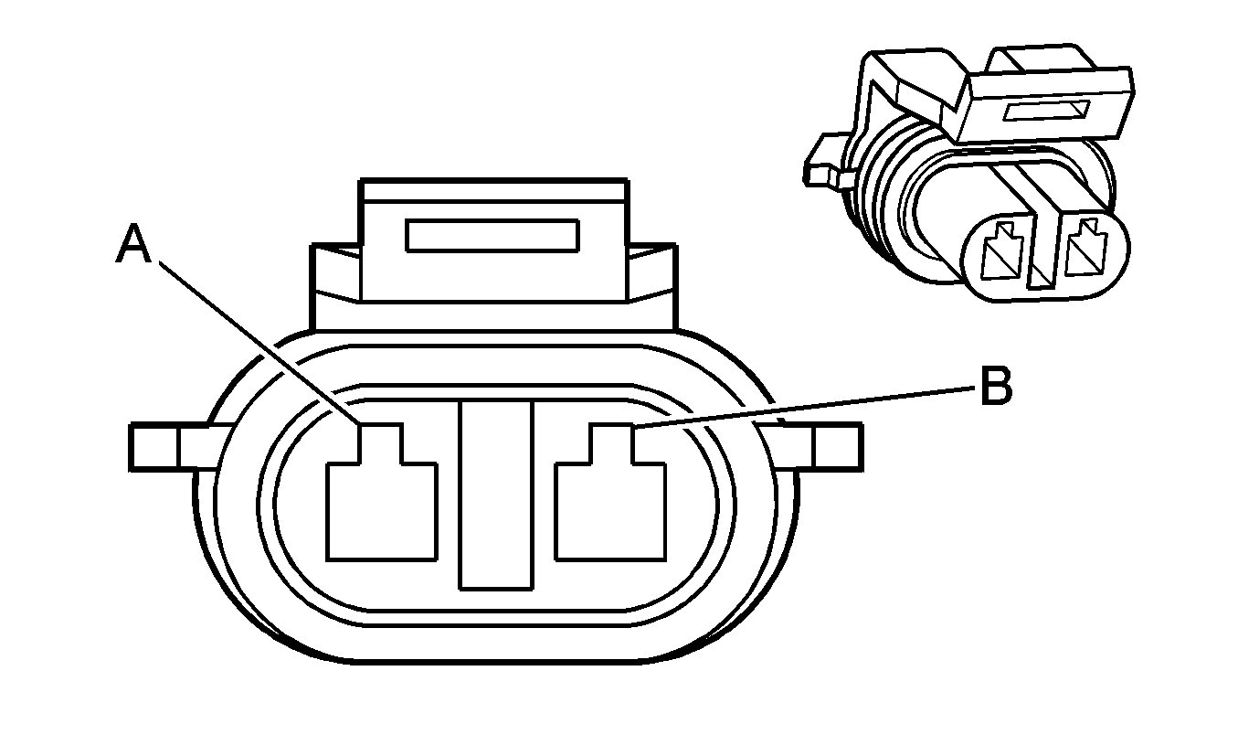
Connector Part Information |
| ||||||
Pin | Wire Color | Circuit No. | Function | ||||
1 | -- | -- | Not Used | ||||
2 | YE | 1045 | RFA Class 2 Serial Data | ||||
3 | -- | -- | Not Used | ||||
4 | BK | 150 | Ground | ||||
5 | BK/YE | 251 | Ground | ||||
6-8 | -- | -- | Not Used | ||||
9 | RD/BK | 800 | UART Serial Data (Primary) | ||||
10-11 | -- | -- | Not Used | ||||
12 | BU/BK | 799 | ABS Serial Data | ||||
13-15 | -- | -- | Not Used | ||||
16 | OG/BK | 740 | Battery Positive Voltage | ||||
| |||||||
|---|---|---|---|---|---|---|---|
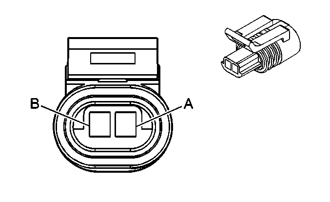
Connector Part Information |
| ||||||
Pin | Wire Color | Circuit No. | Function | ||||
A | GN | 68 | Low Coolant Level Indicator Control | ||||
B | BK/RD | 450 | Ground | ||||
| |||||||
|---|---|---|---|---|---|---|---|
Connector Part Information |
| ||||||
Pin | Wire Color | Circuit No. | Function | ||||
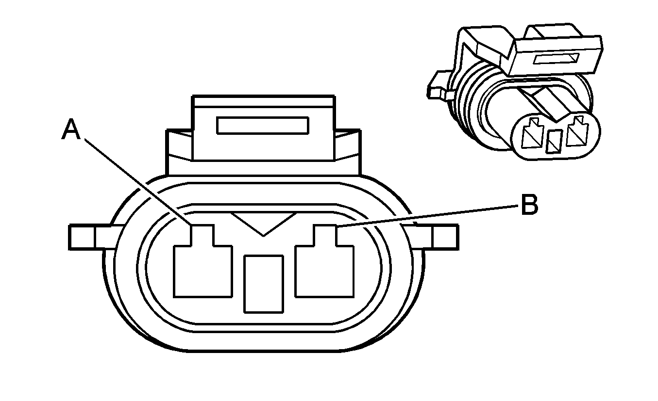
A | GY/BK | 2761 | Low Reference | ||||
B | YE | 410 | ECT Sensor Signal | ||||

| |||||||
|---|---|---|---|---|---|---|---|
Connector Part Information |
| ||||||
Pin | Wire Color | Circuit No. | Function | ||||
A | GN | 470 | Low Reference | ||||
B | BU/YE | 596 | 5-Volt Reference | ||||
C | BU/WH | 331 | Engine Oil Pressure Signal | ||||
| |||||||
|---|---|---|---|---|---|---|---|
Connector Part Information |
| ||||||
Pin | Wire Color | Circuit No. | Function | ||||
A | PK | 439 | Ignition 1 Voltage | ||||
B | GN/YE | 428 | EVAP Canister Purge Solenoid Control | ||||

| |||||||
|---|---|---|---|---|---|---|---|
Connector Part Information |
| ||||||
Pin | Wire Color | Circuit No. | Function | ||||
A | PK | 439 | Ignition 1 Voltage | ||||
B | WH | 1310 | EVAP Canister Vent Solenoid Control | ||||
| |||||||
|---|---|---|---|---|---|---|---|
Connector Part Information |
| ||||||
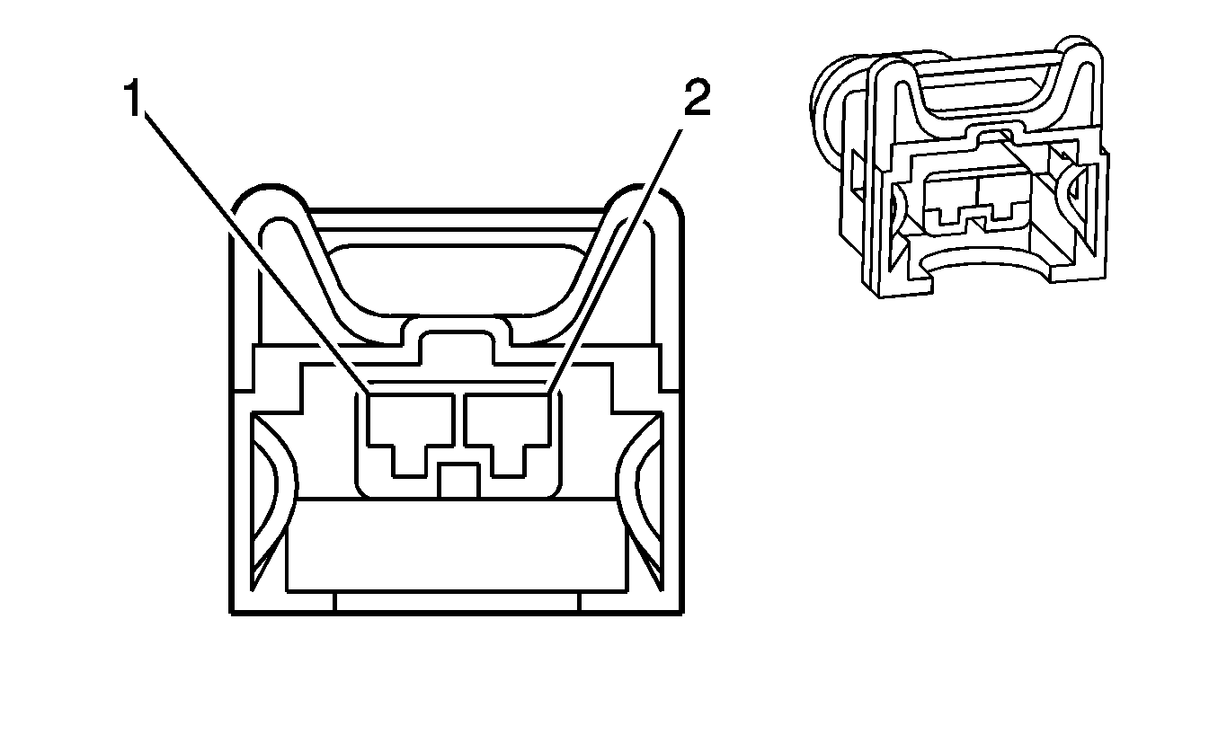
Pin | Wire Color | Circuit No. | Function | ||||
1 | L-GN | 1039 | Ignition 1 Voltage | ||||
2 | BU | 1744 | Fuel Injector #1 Control | ||||

| |||||||
|---|---|---|---|---|---|---|---|
Connector Part Information |
| ||||||
Pin | Wire Color | Circuit No. | Function | ||||
1 | RD | 639 | Ignition 1 Voltage | ||||
2 | GN | 1745 | Fuel Injector #2 Control | ||||

| |||||||
|---|---|---|---|---|---|---|---|
Connector Part Information |
| ||||||
Pin | Wire Color | Circuit No. | Function | ||||
1 | L-GN | 1039 | Ignition 1 Voltage | ||||
2 | PU | 1746 | Fuel Injector #3 Control | ||||

| |||||||
|---|---|---|---|---|---|---|---|
Connector Part Information |
| ||||||
Pin | Wire Color | Circuit No. | Function | ||||
1 | RD | 639 | Ignition 1 Voltage | ||||
2 | BN/YE | 844 | Fuel Injector #4 Control | ||||

| |||||||
|---|---|---|---|---|---|---|---|
Connector Part Information |
| ||||||
Pin | Wire Color | Circuit No. | Function | ||||
1 | L-GN | 1039 | Ignition 1 Voltage | ||||
2 | GY | 845 | Fuel Injector #5 Control | ||||

| |||||||
|---|---|---|---|---|---|---|---|
Connector Part Information |
| ||||||
Pin | Wire Color | Circuit No. | Function | ||||
1 | RD | 639 | Ignition 1 Voltage | ||||
2 | YE | 846 | Fuel Injector #6 Control | ||||

| |||||||
|---|---|---|---|---|---|---|---|
Connector Part Information |
| ||||||
Pin | Wire Color | Circuit No. | Function | ||||
1 | L-GN | 1039 | Ignition 1 Voltage | ||||
2 | PK/BU | 877 | Fuel Injector #7 Control | ||||

| |||||||
|---|---|---|---|---|---|---|---|
Connector Part Information |
| ||||||
Pin | Wire Color | Circuit No. | Function | ||||
1 | RD | 639 | Ignition 1 Voltage | ||||
2 | L-GN | 878 | Fuel Injector #8 Control | ||||
| |||||||
|---|---|---|---|---|---|---|---|
Connector Part Information |
| ||||||
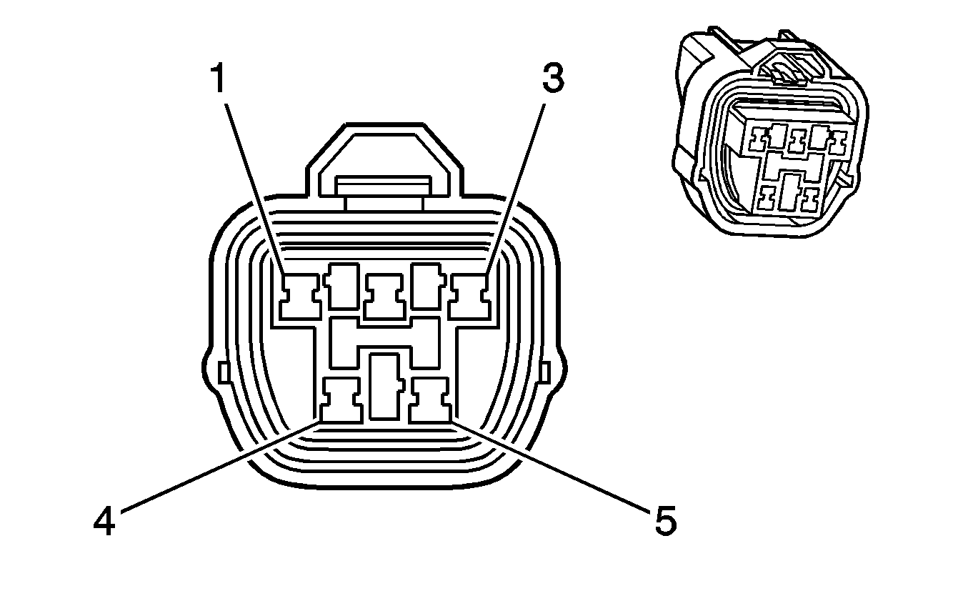
Pin | Wire Color | Circuit No. | Function | ||||
1 | -- | -- | Not Used | ||||
2 | PU | 30 | Fuel Level Sensor Signal | ||||
3 | BK | 2759 | Low Reference | ||||
4 | PU | 120 | Fuel Pump Supply Voltage | ||||
5 | BK/BU | 650 | Ground | ||||

| |||||||
|---|---|---|---|---|---|---|---|
Connector Part Information |
| ||||||
Pin | Wire Color | Circuit No. | Function | ||||
A | BK | 2759 | Low Reference | ||||
B | D-GN | 890 | Fuel Tank Pressure Sensor Signal | ||||
C | GY | 2709 | 5-Volt Reference Voltage | ||||
| |||||||
|---|---|---|---|---|---|---|---|
Connector Part Information |
| ||||||
Pin | Wire Color | Circuit No. | Function | ||||
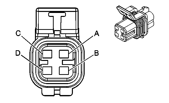
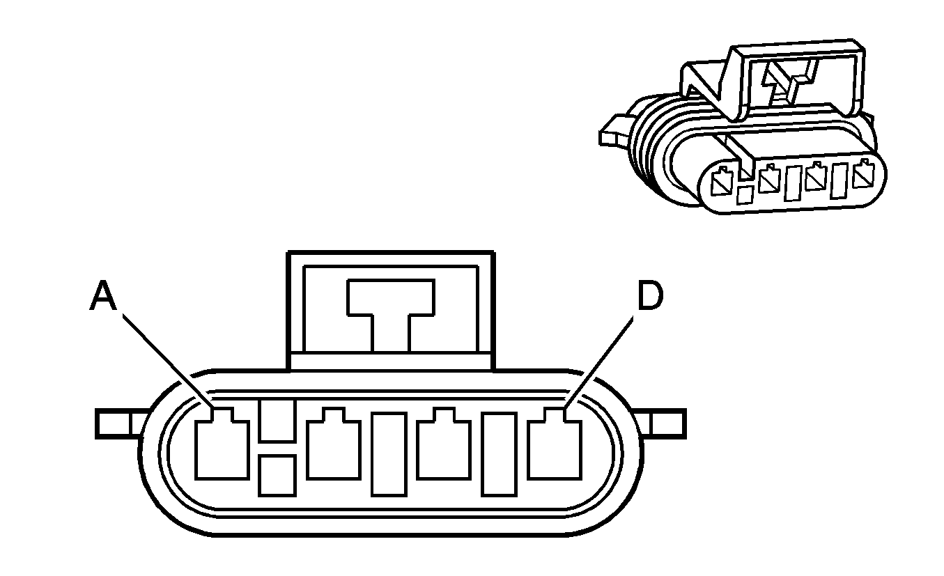
A | BU/BK | 1664 | HO2S Low Signal Bank 1 Sensor 1 | ||||
B | PU | 1665 | HO2S High Signal Bank 1 Sensor 1 | ||||
C | BK/WH | 1050 | HO2S Bank 1 Sensor 1 Heater Low Control | ||||
D | PK | 439 | Ignition 1 Voltage | ||||
| |||||||
|---|---|---|---|---|---|---|---|
Connector Part Information |
| ||||||
Pin | Wire Color | Circuit No. | Function | ||||
A | TN/WH | 1669 | HO2S Low Signal Bank 1 Sensor 2 | ||||
B | PU/WH | 1668 | HO2S High Signal Bank 1 Sensor 2 | ||||
C | L-BU | 1150 | HO2S Bank 1 Sensor 2 Heater Low Control | ||||
D | PK | 439 | Ignition 1 Voltage | ||||

| |||||||
|---|---|---|---|---|---|---|---|
Connector Part Information |
| ||||||
Pin | Wire Color | Circuit No. | Function | ||||
A | GY/BK | 1667 | HO2S Low Signal Bank 2 Sensor 1 | ||||
B | GY | 1666 | HO2S High Signal Bank 2 Sensor 1 | ||||
C | L-GN/RD | 1250 | HO2S Bank 2 Sensor 1 Heater Low Control | ||||
D | PK | 439 | Ignition 1 Voltage | ||||

| |||||||
|---|---|---|---|---|---|---|---|
Connector Part Information |
| ||||||
Pin | Wire Color | Circuit No. | Function | ||||
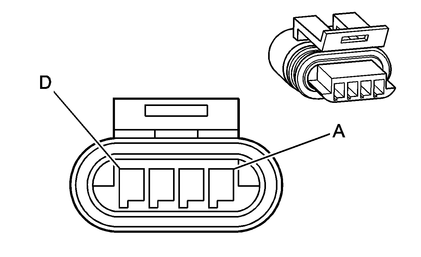
A | TN | 1671 | HO2S Low Signal Bank 2 Sensor 2 | ||||
B | PU/BK | 1670 | HO2S High Signal Bank 2 Sensor 2 | ||||
C | RD/WH | 1350 | HO2S Bank 2 Sensor 2 Heater Low Control | ||||
D | PK | 439 | Ignition 1 Voltage | ||||
| |||||||
|---|---|---|---|---|---|---|---|
Connector Part Information |
| ||||||
Pin | Wire Color | Circuit No. | Function | ||||
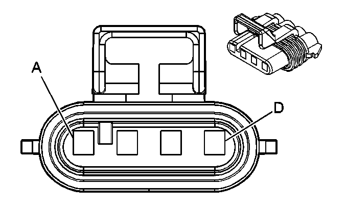
A | L-GN/BK | 444 | IAC Coil B Low Control | ||||
B | L-GN/WH | 1749 | IAC Coil B High Control | ||||
C | L-BU/BK | 1748 | IAC Coil A Low Control | ||||
D | L-BU | 1747 | IAC Coil A High Control | ||||
| |||||||
|---|---|---|---|---|---|---|---|
Connector Part Information |
| ||||||
Pin | Wire Color | Circuit No. | Function | ||||
A | BK | 450 | Ground | ||||
B | BN | 2129 | Low Reference | ||||
C | PU | 2121 | IC 1 Control | ||||
D | PK | 1039 | Ignition 1 Voltage | ||||

| |||||||
|---|---|---|---|---|---|---|---|
Connector Part Information |
| ||||||
Pin | Wire Color | Circuit No. | Function | ||||
A | BK | 450 | Ground | ||||
B | BN | 2122 | IC 2 Control | ||||
C | RD | 2130 | Low Reference | ||||
D | PK | 639 | Ignition 1 Voltage | ||||

| |||||||
|---|---|---|---|---|---|---|---|
Connector Part Information |
| ||||||
Pin | Wire Color | Circuit No. | Function | ||||
A | BK | 450 | Ground | ||||
B | BN | 2129 | Low Reference | ||||
C | L-BU | 2123 | IC 3 Control | ||||
D | PK | 1039 | Ignition 1 Voltage | ||||

| |||||||
|---|---|---|---|---|---|---|---|
Connector Part Information |
| ||||||
Pin | Wire Color | Circuit No. | Function | ||||
A | BK | 450 | Ground | ||||
B | BN | 2130 | Low Reference | ||||
C | L-GN | 2124 | IC 4 Control | ||||
D | PK | 639 | Ignition 1 Voltage | ||||

| |||||||
|---|---|---|---|---|---|---|---|
Connector Part Information |
| ||||||
Pin | Wire Color | Circuit No. | Function | ||||
A | BK | 450 | Ground | ||||
B | BN | 2129 | Low Reference | ||||
C | GN | 2125 | IC 5 Control | ||||
D | PK | 1039 | Ignition 1 Voltage | ||||

| |||||||
|---|---|---|---|---|---|---|---|
Connector Part Information |
| ||||||
Pin | Wire Color | Circuit No. | Function | ||||
A | BK | 450 | Ground | ||||
B | BN | 2130 | Low Reference | ||||
C | L-BU | 2126 | IC 6 Control | ||||
D | PK | 639 | Ignition 1 Voltage | ||||

| |||||||
|---|---|---|---|---|---|---|---|
Connector Part Information |
| ||||||
Pin | Wire Color | Circuit No. | Function | ||||
A | BK | 450 | Ground | ||||
B | BN | 2127 | IC 7 Control | ||||
C | RD | 2129 | Low Reference | ||||
D | PK | 1039 | Ignition 1 Voltage | ||||

| |||||||
|---|---|---|---|---|---|---|---|
Connector Part Information |
| ||||||
Pin | Wire Color | Circuit No. | Function | ||||
A | BK | 450 | Ground | ||||
B | BN | 2130 | Low Reference | ||||
C | PU | 2128 | IC 8 Control | ||||
D | PK | 639 | Ignition 1 Voltage | ||||

| |||||||
|---|---|---|---|---|---|---|---|
Connector Part Information |
| ||||||
Pin | Wire Color | Circuit No. | Function | ||||
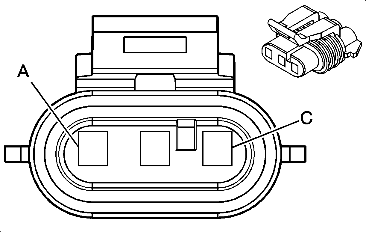
A | GN/OG | 5514 | Low Reference | ||||
B | BN | 472 | IAT Sensor Signal | ||||
| |||||||
|---|---|---|---|---|---|---|---|
Connector Part Information |
| ||||||
Pin | Wire Color | Circuit No. | Function | ||||
A | BK | 469 | Low Reference | ||||
B | L-GN | 432 | MAP Sensor Signal | ||||
C | PU/WH | 2704 | 5-Volt Reference | ||||

| |||||||
|---|---|---|---|---|---|---|---|
Connector Part Information |
| ||||||
Pin | Wire Color | Circuit No. | Function | ||||
A | BN/WH | 492 | MAF Sensor Signal | ||||
B | BK/RD | 450 | Sensor Ground | ||||
C | PK | 439 | Sensor Voltage Supply | ||||
| |||||||
|---|---|---|---|---|---|---|---|
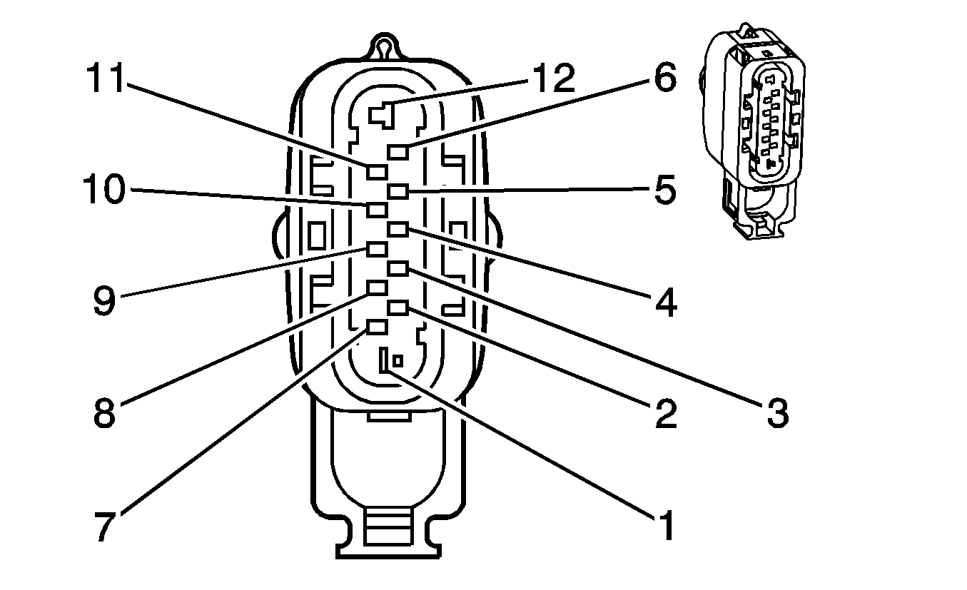
Connector Part Information |
| ||||||
Pin | Wire Color | Circuit No. | Function | ||||
1 | GY/BU | 275 | Park Neutral Position Switch Park Signal | ||||
2 | -- | -- | Not Used | ||||
3 | YE | 1479 | A/T Neutral Signal | ||||
4 | YE/RD | 772 | Transmission Range Switch Signal B | ||||
5 | BU/WH | 771 | Transmission Range Switch Signal A | ||||
6 | GY | 773 | Transmission Range Switch Signal C | ||||
7 | BK/RD | 450 | Ground | ||||
8 | WH | 776 | Transmission Range Switch Signal P | ||||
9 | -- | -- | Not Used | ||||
10 | L-GN | 24 | Backup Lamp Supply Voltage | ||||
11 | BN/BU | 239 | Ignition 1 Voltage | ||||
12 | GY | 434 | Neutral Safety Switch Signal | ||||
| |||||||
|---|---|---|---|---|---|---|---|
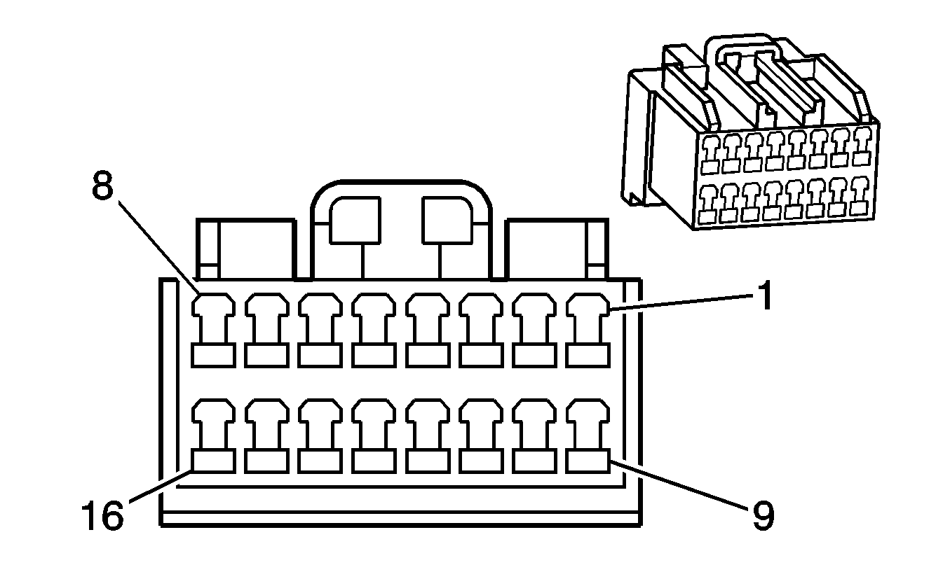
Connector Part Information |
| ||||||
Pin | Wire Color | Circuit No. | Function | ||||
1-5 | -- | -- | Not Used | ||||
6 | RD/BK | 800 | UART Serial Data (Primary) | ||||
7 | YE | 1045 | RFA Class 2 Serial Data | ||||
8 | GY/BU | 275 | Park Neutral Position Switch Park Signal | ||||
9-14 | -- | -- | Not Used | ||||
15 | OG | 300 | Ignition 3 Voltage | ||||
16 | BK/RD | 450 | Ground | ||||
| |||||||
|---|---|---|---|---|---|---|---|
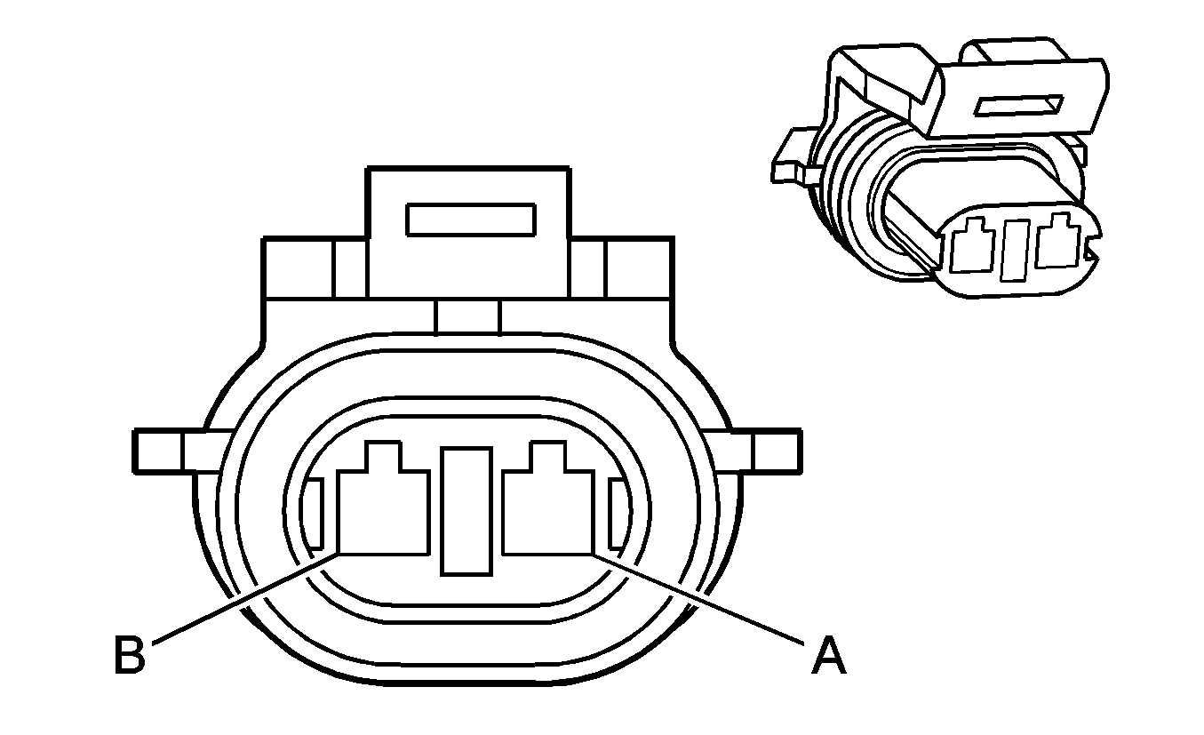
Connector Part Information |
| ||||||
Pin | Wire Color | Circuit No. | Function | ||||
A | YE | 1652 | Reverse Lockout Solenoid Control | ||||
B | PK/BU | 339 | Ignition 1 Voltage | ||||

| |||||||
|---|---|---|---|---|---|---|---|
Connector Part Information |
| ||||||
Pin | Wire Color | Circuit No. | Function | ||||
A | GY | 587 | Skip/Shift Solenoid Control | ||||
B | PK/BU | 339 | Ignition 1 Voltage | ||||

| |||||||
|---|---|---|---|---|---|---|---|
Connector Part Information |
| ||||||
Pin | Wire Color | Circuit No. | Function | ||||
A | GY | 2701 | 5-Volt Reference | ||||
B | BK/YE | 2752 | Low Reference | ||||
C | BU | 411 | Throttle Position Signal | ||||
| |||||||
|---|---|---|---|---|---|---|---|
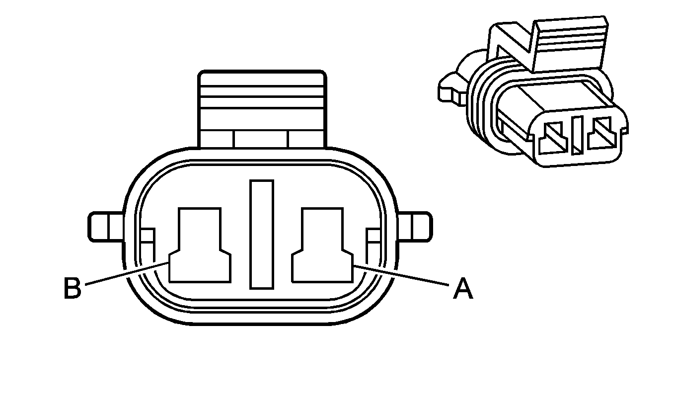
Connector Part Information |
| ||||||
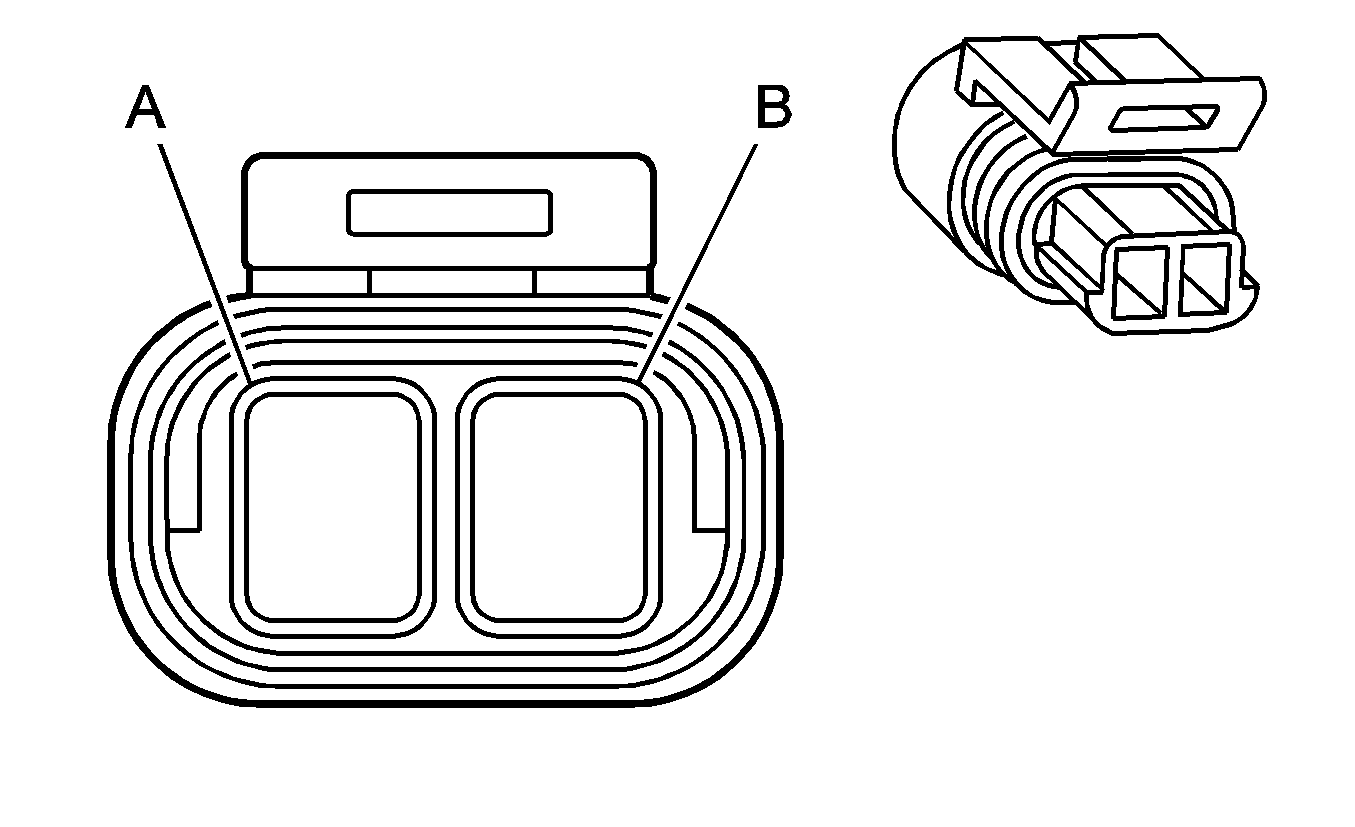
Pin | Wire Color | Circuit No. | Function | ||||
A | RD/WH | 560 | Throttle Relaxer Motor - Feed | ||||
B | RD/BK | 561 | Throttle Relaxer Motor - Return | ||||
| |||||||
|---|---|---|---|---|---|---|---|
Connector Part Information |
| ||||||
Pin | Wire Color | Circuit No. | Function | ||||
A | BU/WH | 1230 | AT ISS High Signal | ||||
B | BN/RD | 1231 | AT ISS Low Signal | ||||
