Tools Required
| • | J 39580 Engine Support Table |
| • | J 39580-500 Engine Support Table Top |
| • | J 41798 Engine Lifting Brackets |
| • | J 42203 Driveline Support |
| • | J 36221 Hydraulic Clutch Line Separator |
| • | J 36660-A Torque Angle Meter |
Removal Procedure
Important: The steps in the following procedure are in a specific order. Follow these steps in this order and do not ignore any details .
- Disconnect the negative battery cable.
- Recover the air conditioning (A/C) refrigerant. Refer to Refrigerant Recovery and Recharging in Heating, Ventilation and Air Conditioning.
- Remove the hood. Refer to Hood Replacement in Body Front End.
- Remove the front suspension support brace. Refer to Front Suspension Support Brace Replacement .
- Remove the fuel rail covers.
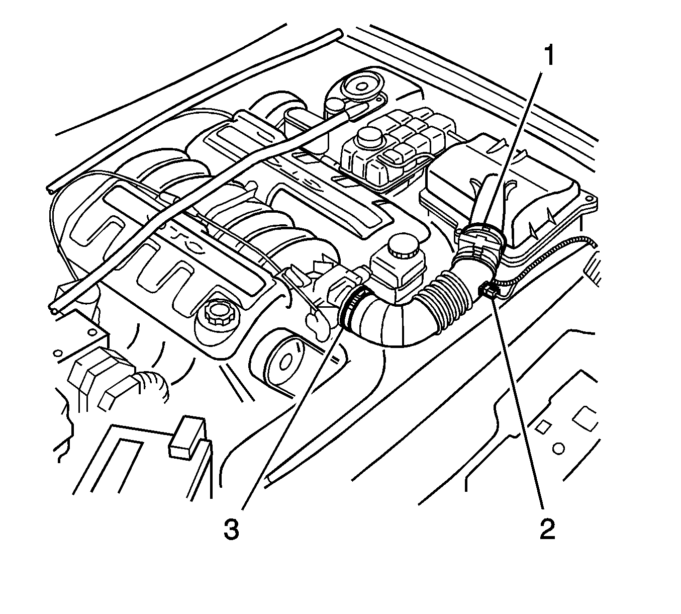
- Disconnect the air intake sensor connector (2) from the air intake sensor.
- Loosen the hose clamps (1, 3) securing the intake duct.
- Remove the intake duct from the vehicle.
- Depressurize the fuel system . Refer to Fuel Pressure Relief in Engine Controls.
- Remove the radiator. Refer to Radiator Replacement in Engine Cooling.
- Remove the radiator hoses from the water pump.
- Remove the heater hoses from the water pump.
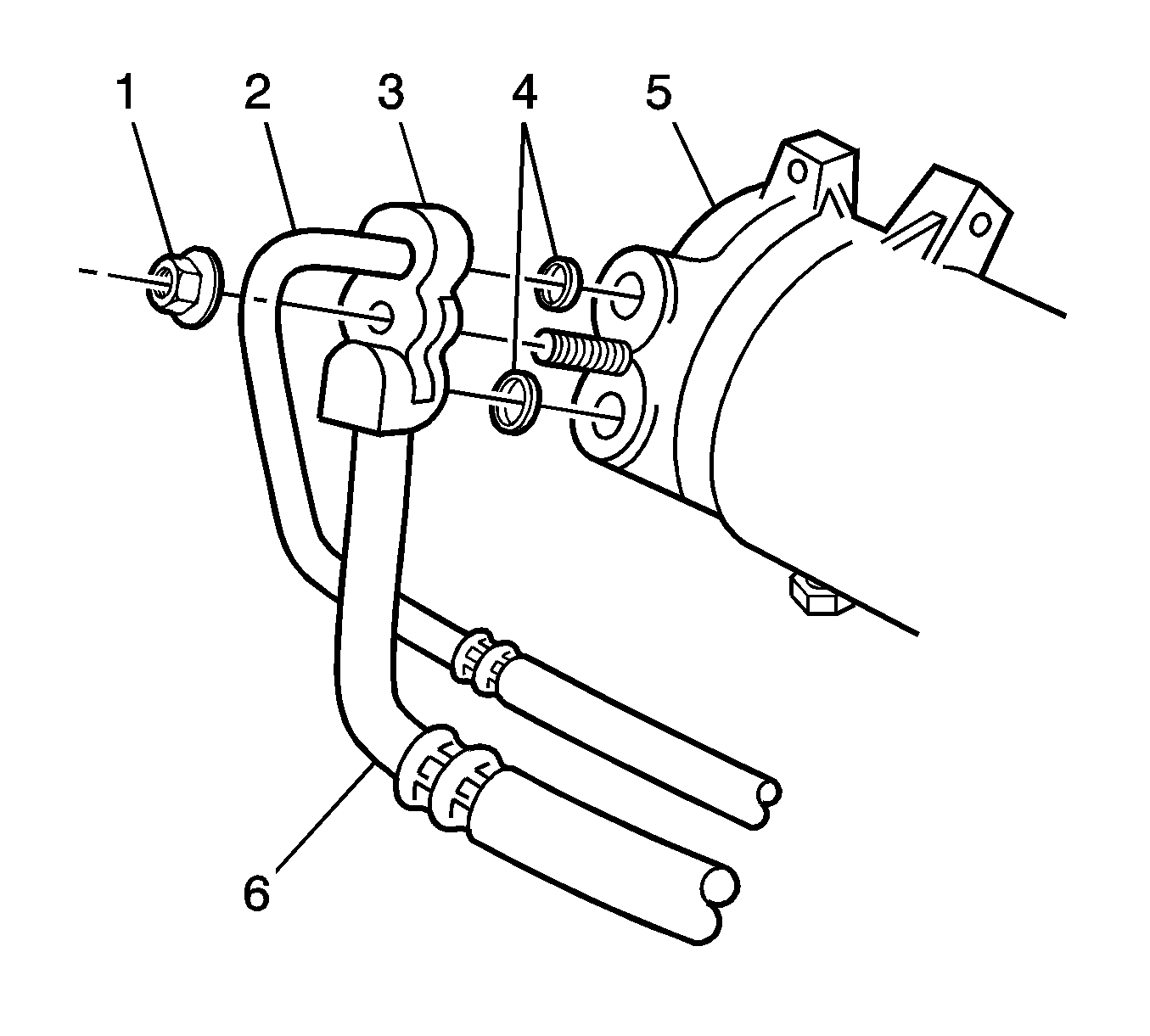
- Remove the A/C compressor and condenser hose nut (1) at the compressor.
- Separate the A/C compressor and condenser hose (5) from the A/C compressor (5).
- Remove the ground lead screw from the engine block and left hand engine mount.
- Remove the nut securing the battery harness ground terminals to the antilock brake system (ABS)/traction control system (TCS) control module bracket stud.
- Disconnect the positive lead terminal from the battery. Lay the harness on the engine.
- Disconnect the A/C wiring harness connector
- Disconnect the wiring harness retaining clips from the engine compartment.
- Disconnect the connector from the theft deterrent horn.
- Remove the coolant surge tank. Refer to Radiator Surge Tank Replacement in Engine Cooling.
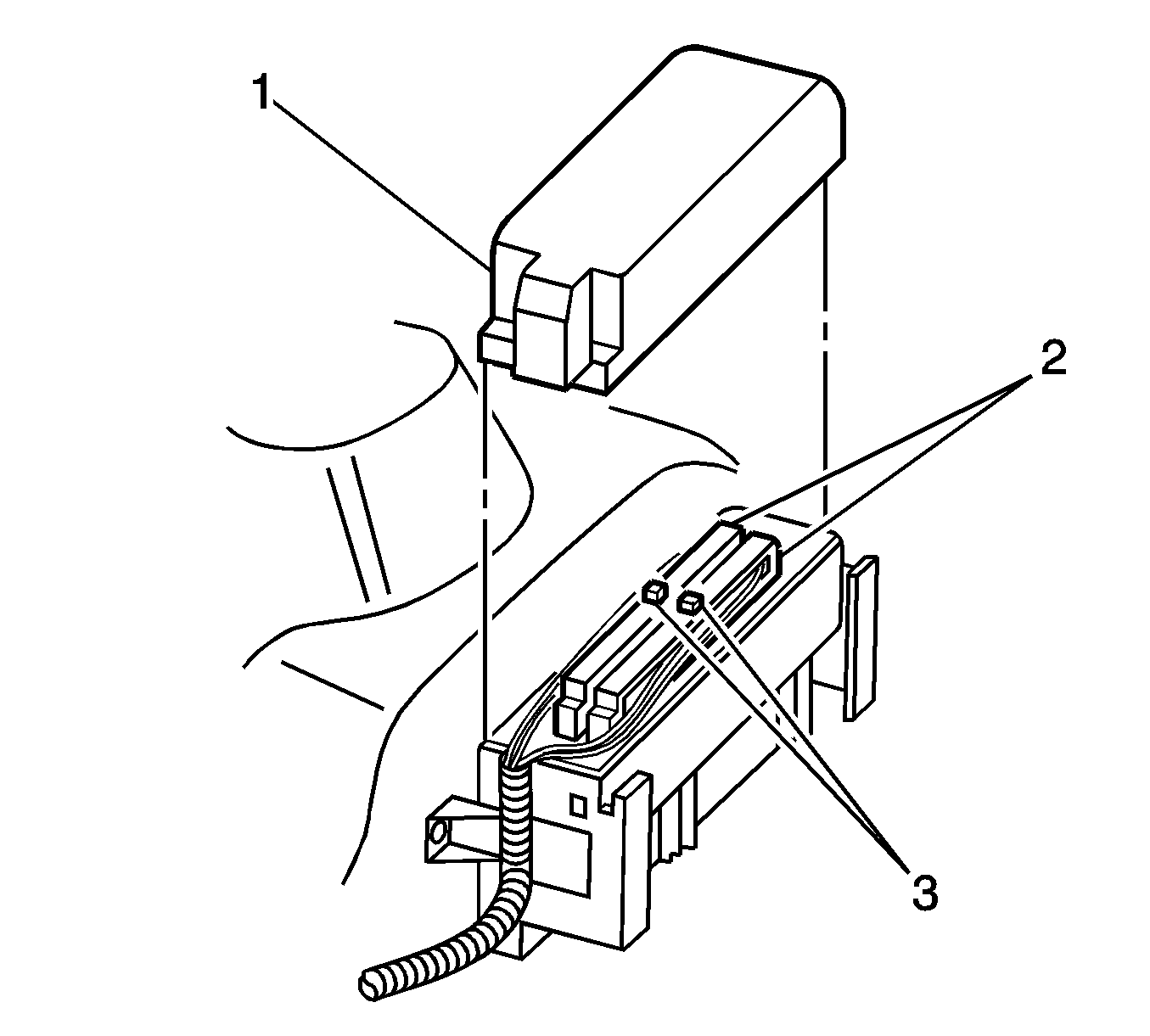
- Remove the powertrain control module (PCM) harness connector cover (1).
- Loosen the connector retaining screws at each PCM connector (2), then remove the connectors from the PCM.
- Disconnect the PCM wiring harness retaining clip.
- Remove the engine wiring harness retaining clip from the power steering pipe bracket.
- Remove the powertrain interface module (PIM) and the throttle relaxer module (TRM) as an assembly. Refer to Throttle Relaxer Assembly Replacement in Antilock Brake System.
- Cut the wiring harness straps and discard.
- Disconnect the powertrain to main wiring harness connector.
- Remove the harness to dash panel grommet and feed the harness and connectors out into the engine bay.
- Place the powertrain wiring harness on top of the engine.
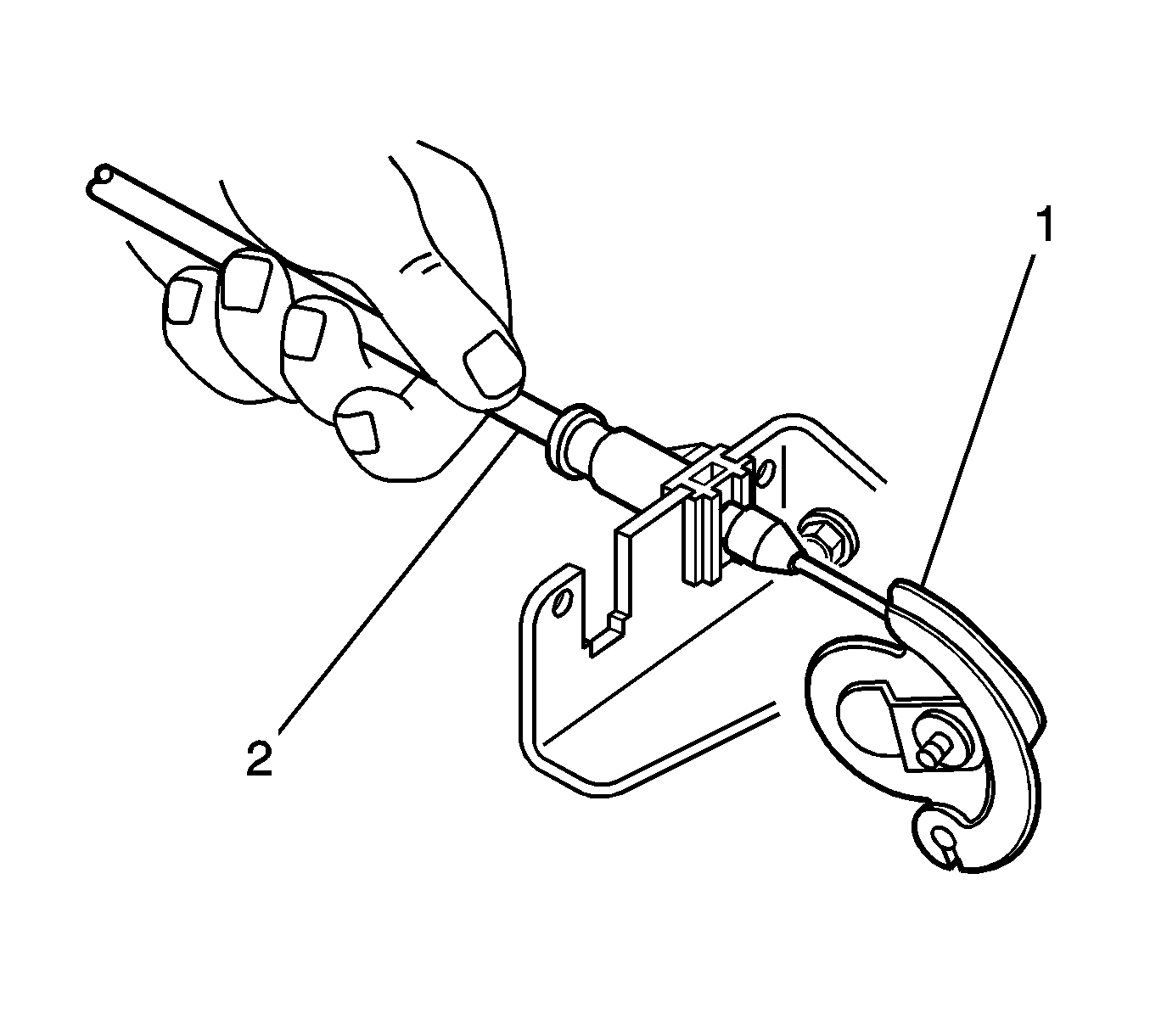
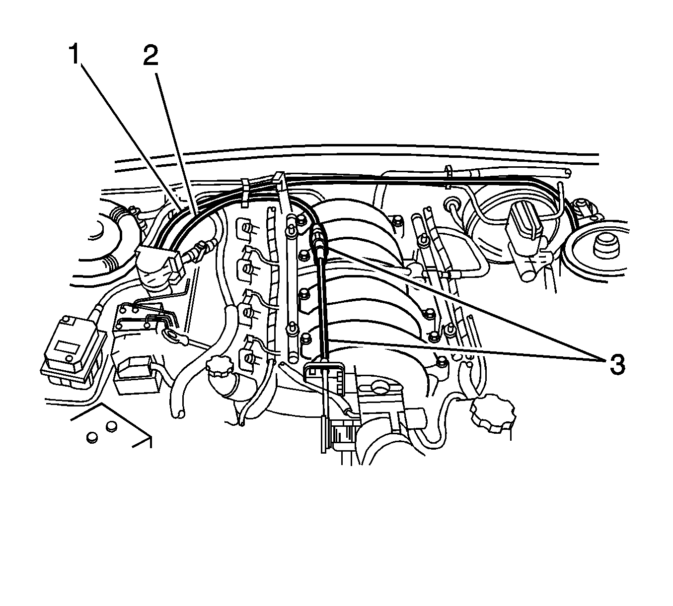
- Lift the throttle cable (2) up at the throttle body mounting bracket, then remove the cable from the throttle body cam lever (1).
- Set the throttle cable aside.
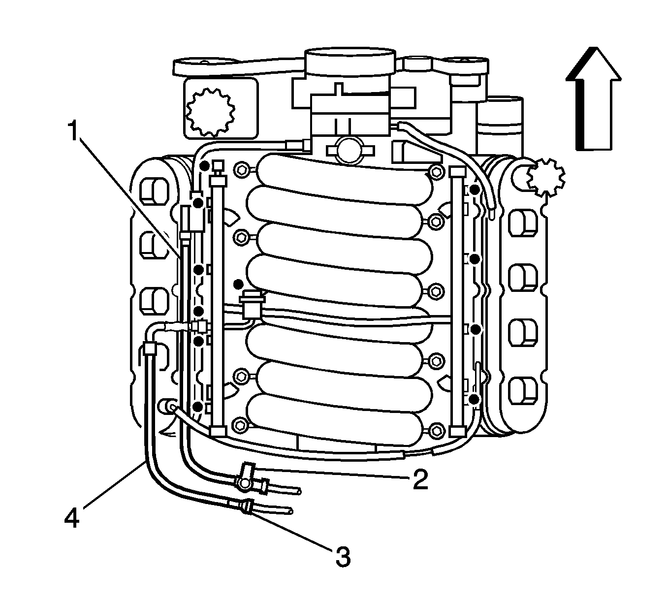
- Disconnect the fuel line (4) from the fuel rail. Refer to Fuel Hose/Pipes Replacement - Engine Compartment in Engine Controls.
- Disconnect the purge line (1) from the purge valve.
- Loosen the hose clamp on the return hose at the power steering reservoir.
- Place a suitable container under the reservoir and remove the hose and drain the reservoir fluid.
- Remove the high pressure line flare nut and O-ring from the pump outlet fitting at the rear of the power steering pump.
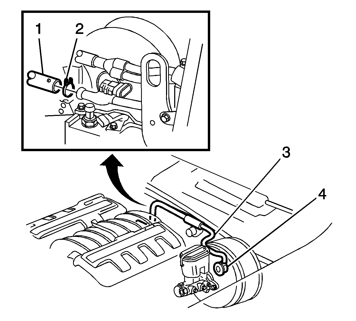
- Disconnect the brake booster vacuum hose (1) and heater control, vacuum hose from the rear of the intake manifold.
- Remove the four bolts securing the undertray to the crossmember.
- Remove the tray from the crossmember.
- Remove the 2 bolts securing the power steering high pressure line brackets to the oil pan.
- Remove both exhaust manifolds. Refer to Exhaust Manifold Replacement - Left Side and Exhaust Manifold Replacement - Right Side in Engine Exhaust.
- Remove the transmission. Refer to Transmission Replacement in Manual Transmission - Tremec 6-Speed and Transmission Replacement in Automatic Transmission - 4L60-E/4L65-E.
- Remove the right and left engine mount to engine bracket nuts.
- Attach a suitable lifting chain and hooks to the 2 engine lifting brackets.
- Using a suitable lifting crane, slightly raise the engine to clear the engine mount stud.
- Slowly lift the engine out of the engine bay.

Important: Cap the hoses and inlets when separating the cooling system components, this prevents dirt and other contaminants from entering the cooling system.

Installation Procedure
- Prepare the engine for installation. Refer to Engine Prelubing .
- Install the J 41798 to the engine.
- Using an engine hoist and the J 41798 raise the engine slightly.
- Remove the engine from the engine stand.
- Using an engine hoist and the J 41798 lower the engine onto the crossmember.
- Install the right and left engine mount to engine bracket nuts.
- Remove the J 41798 from the engine.
- Install the transmission. Refer to Transmission Replacement in Manual Transmission - Tremec 6-Speed and Transmission Replacement in Automatic Transmission - 4L60-E/4L65-E.
- Install both exhaust manifolds. Refer to Exhaust Manifold Replacement - Left Side and Exhaust Manifold Replacement - Right Side in Engine Exhaust.
- Install the power steering high pressure line brackets to the oil pan. Secure with the 2 bolts.
- Install the tray to the crossmember. Secure with the four bolts.
- Connect the brake booster vacuum hose (1) and heater control, vacuum hose to the rear of the intake manifold.
- Install the high pressure line flare nut and O-ring to the pump outlet fitting at the rear of the power steering pump.
- Install the hose to the reservoir fluid. Secure the hose with the hose clamp.
- Connect the fuel line (4) to the fuel rail. Refer to Fuel Hose/Pipes Replacement - Engine Compartment in Engine Controls.
- Connect the purge line (1) to the purge valve.
- Install the cable to the throttle body cam lever (1) then install the throttle cable (2) to the throttle body mounting bracket.
- Install the cable (3) to the retaining clip.
- Feed the harness and connectors into the passenger compartment and install the dash panel grommet.
- Connect the powertrain to main wiring harness connector.
- Install harness straps to retain the wiring harness.
- Install the PIM and the TRM. Refer to Throttle Relaxer Assembly Replacement in Antilock Brake System.
- Install the engine wiring harness retaining clip to the power steering pipe bracket.
- Connect the PCM wiring harness retaining clip.
- Connect the connectors (2) to the PCM. Secure with the screws.
- Install the PCM harness connector cover (1).
- Install the coolant surge tank. Refer to Radiator Surge Tank Replacement in Engine Cooling.
- Connect the connector to the theft deterrent horn.
- Connect the wiring harness retaining clips to the engine compartment.
- Connect the A/C wiring harness connector.
- Connect the positive lead terminal to the battery.
- Install the nut securing the battery harness ground terminals to the ABS/TCS control module bracket stud.
- Install the ground lead screw to the engine block and left hand engine mount.
- Install new O-rings (4) onto the A/C compressor hose block fitting (3). Refer to O-Ring Replacement in Heating, Ventilation and Air Conditioning.
- Install the A/C compressor and condenser hose to the A/C compressor (5). Secure with the nut (1).
- Install the heater hoses to the water pump. Secure with the clamps.
- Install the radiator hoses to the water pump. Secure with the clamps.
- Install the radiator. Refer to Radiator Replacement in Engine Cooling.
- Install the intake duct to the vehicle.
- Secure the intake duct with the hose clamps (1,3).
- Connect the air intake sensor connector (2) to the air intake sensor.
- Install the fuel rail covers.
- Install the front suspension support brace. Refer to Front Suspension Support Brace Replacement .
- Install the hood. Refer to Hood Replacement in Body Front End.
- Recharge the A/C system. Refer to Refrigerant Recovery and Recharging in Heating, Ventilation and Air Conditioning.
- Fill the crankcase with the proper quantity and grade of engine oil. Refer to Approximate Fluid Capacities and Fluid and Lubricant Recommendations in Maintenance and Lubrication.
- Connect the negative battery cable.
- Disable the ignition system.
- Crank the engine several times. Listen for any unusual noises or evidence that parts are binding.
- Enable the ignition system.
- Start the engine and listen for unusual noises.
- Check the vehicle oil pressure gage and confirm that the engine has acceptable oil pressure.
- Run the engine speed at about 1,000 RPM until the engine has reached normal operating temperature.
- Listen for sticking lifters and other unusual noises.
- Inspect for fuel, oil, and/or other coolant leaks while the engine is running.
- Perform a final inspection for the proper engine oil and coolant levels.

Important: The steps in the following procedure are in a specific order. Follow these steps in this order and ignore no details.
Notice: Use the correct fastener in the correct location. Replacement fasteners must be the correct part number for that application. Fasteners requiring replacement or fasteners requiring the use of thread locking compound or sealant are identified in the service procedure. Do not use paints, lubricants, or corrosion inhibitors on fasteners or fastener joint surfaces unless specified. These coatings affect fastener torque and joint clamping force and may damage the fastener. Use the correct tightening sequence and specifications when installing fasteners in order to avoid damage to parts and systems.
Tighten
Tighten the nut to 80 N·m (59 lb ft).
Tighten
Tighten the nut to 25 N·m (18 lb ft).
Tighten
Tighten the nut to 30 N·m (22 lb ft).



Tighten
Tighten the nut to 9 N·m (80 lb in).

Tighten
Tighten the nut to 30 N·m (22 lb ft).


If necessary, install an oil pressure gage and measure the engine oil pressure.
