
| Subject: | G8 New Model Features and Service Guide |
| Models: | 2008-2009 Pontiac G8 |
This bulletin is being revised to add the 2009 model year, add information in the following sections: Quality PDI Instructions - Sunroof Initialization, Brake Disc Protection Covers and Rapguard and Scotchcal removal and provide clarifications for
Canada. Please discard Corporate Bulletin Number 08-00-89-008 (Section 00 - General Information).
This is a special bulletin to introduce the 2008-2009 Pontiac G8. The purpose of this bulletin is to make you familiar with the vehicle's features and describe the action your Service Department will need to take to ensure that your dealership is able
to fully service this vehicle.
ABOUT THE VEHICLE
The 2008-2009 G8 and G8 GT are all new models with completely new body structure, chassis and electrical architecture.
Powertrain
Engine
Two basic engine configurations are available:
| • | 6.0L V8 L76/ Gen IV (available only on GT model)
|
Engine Specifications
Engine Specifications
|
| G8
| G8 GT
|
Configuration
| 3.6L VVT DOHC V6
| 6.0L SFI V8
Active Fuel Management
|
Displacement --cubic inches/cc
| 217/3564
| 364/5967
|
Throttle Control
| Electronic Throttle Control
| Electronic Throttle Control with Active Fuel Management
|
Horsepower @ rpm
| 256 hp @ 6300 rpm
| 361 hp @ 5300 rpm
|
Torque (foot pounds) @ rpm
| 248 lb-ft @ 2100 rpm
| 385 lb-ft torque @ 4400 rpm
|
Transmission
The 3.6L engine is combined with the 5L40E automatic transmission. Driver shift control (DSC) allows the transmission to be shifted like a clutchless manual. The "sport mode" holds shifts longer for maximum power.
The 6.0L engine is combined with the 6L80E automatic transmission. The "sport mode" holds shifts longer for maximum power. There are two overdrive gears for maximum fuel economy. A wider gear ratio spread allows both aggressive launch performance
and low revs when cruising on the highway. Driver shift control (DSC) allows the transmission to be shifted like a clutchless manual.
Chassis/Suspension
Wheel and Tires
| • | 18" silver-painted aluminum wheels with a split-spoke design -- standard on G8. |
| • | 18" machine-faced aluminum wheels with a 5-spoke design and silver-painted inset -- standard on GT. |
| • | 19" machine-faced aluminum wheels with a 5-spoke design -- available on GT as part of the Sport Package. |
| • | P245/45R18 all-season blackwall tires -- standard on G8 and available on GT (standard on GT in Canada). |
| • | P245/45R18 summer-only performance blackwall tires -- standard on GT and available on G8 (except in Canada). |
| • | P245/40R19 summer-only performance blackwall tires -- available on GT as part of the Sport Package. |
Brakes
Both models use 4-wheel vented discs with an antilock brake system (ABS) and StabiliTrac®. GT models are equipped with larger rotors.
Body and Trim
The body structure features a highly rigid monocoque construction which is all new for 2008-2009 model year. The body systems, including all body electrical systems, are unique to this vehicle and are new for 2008.
Keys
Important: Keys are ordered through GM SPO with overnight service from FM-Reps. Refer to Corporate Bulletin Number 08-00-89-012 (Key Cutting Procedure for Obtaining Replacement Key).
Ignition/door lock keys for the 2008-2009 model year are of a new design featuring either an attached remote "fixed" key or an attached compact "flip" key housing. The key design is similar to the 2004-2006 GTO; however, an 8-bit
code will replace the previous 10-bit code and will require a new code adapter to enable keys to be cut from the key code using previously specified "Silca" key cutting equipment. A third key (no remote) is for the glove box lock.
Remote Keyless Entry (RKE) System and Operation
Important: The vehicle will ONLY lock the doors with the RKE transmitter or key IF the doors are open. The console door lock switch WILL NOT lock if any of the doors are open.
Important: For each vehicle, there is one flip key with an RKE attached to an RKE transmitter, one fixed key with a transmitter and one key for the glove box lock.
The RKE transmitter functions will work up to 60m (195 ft) away. However, the operating range might be less if the vehicle is running. The RKE transmitter has the following functions:
| • | Lock -- Press this button to lock all doors. |
| • | Unlock -- Press this button to unlock the driver door only or all doors. The unlock function can be customized using the Driver Information Center (e.g. unlock all doors with a single press of the button). |
| • | Trunk -- Press this button to unlatch the trunk. |
| | An emergency trunk release handle is located just inside the rear pass-through and can be used to unlatch the trunk in case of battery failure. |
| • | Remote Start -- This button will appear on the RKE if the vehicle is equipped with remote start. Press this button to start the engine. After you press the door lock button, you must press and hold the Remote Start button for about 3 seconds.
The remote start will not work under the following conditions: |
| - | The vehicle's key is in the ignition. |
| - | The vehicle's hood or door are not closed. |
| - | The hazard warning flashers are on. |
| - | There is an emission control system malfunction. |
| - | The engine coolant temperature is too high. |
| - | The oil pressure is too low. |
| - | Two remote vehicle starts have already been used. The maximum number of remote starts or remote start attempts between ignition cycles with the key is two. |
| - | The vehicle is not in PARK (P). |
| • | Vehicle Locator/Panic Alarm -- Press and release the red button to locate the vehicle. The exterior lamps will flash and the horn will sound. Press and hold the button to activate the panic alarm. The turn signals will flash and the horn will
sound. To cancel the alarm, press the button again or turn the ignition key on the On position. |
Fluids and Lubricants
Many of the fluids and lubricants specified for the G8 are new. Please take the time to confirm that the fluids and lubricants listed below are available in your dealership. Please ensure that only correct fluids and lubricants are used. Damage may result
from use of incorrect materials. The following chart summarizes some of the most critical. Please refer to SI and the Owner Manual for a complete list.
Location
| Fluid/Lubricant
| Quantity
|
Fuel
| Use unleaded fuel with a posted octane rating of 87 or higher for best performance
| Tank capacity:19.3 gal (73L)
|
Engine Oil with Filter
| GM6094M, SAE 5W-30
| V6: 7.1 qt (6.7L)
V8: 8.8 qt (8.3L)
|
Engine Coolant
| DEX-COOL® (GM6277M) 50% concentration
| V6: 10.6 qt (10L)
V8: 11.6 qt (11L)
|
Auto Trans Oil
| DEXRON® VI Automatic Transmission Fluid
| 5L40E: 10.5 qt (9.9L) Total
6L80E: 11.2 qt (10.6L) Total
|
Rear Axle
| Castrol SAF -- Carbon modified. Fully Synthetic P/N 92184900 (in Canada, P/N 88862826)
| 1.2 qt (1.1L)
|
Brakes
| Heavy Duty Brake Fluid to DOT 4 plus P/N 88958860 (in Canada, P/N 88901244)
| --
|
Power Steering
| DEXRON® VI Automatic Transmission Fluid
| --
|
Battery
| 12 V 780 CCA, 80 AH, C Terminal (RH positive)
| --
|
Service Support
Battery Location
The battery is located in the vehicle trunk. To prevent explosive gases from entering the passenger compartment, the battery is fitted with an external ventilation tube which carries gases to the outside of the passenger compartment. Replacement battery
must incorporate the external ventilation feature which must be correctly fitted when the battery is installed. It is vital that in the event that the battery is removed from the vehicle that the ventilation tube be securely refitted when the battery is reinstalled.
To ensure that battery is delivered in best possible condition, a "transit protection connector" is located above the battery in the vehicle trunk is disconnected, isolating circuits which will contribute to parasitic battery drain. This connector
must be connected to enable operation of radio, instrument cluster, central locking, etc.
Key Cutting
Ignition/door lock keys for the 2008-2009 model year are of a new design featuring either attached remote key "fixed" housing or attached compact "flip" key housing. The key design is similar to the 2004-2006 GTO; however, an 8-bit
code will replace the previous 10-bit code and will require a new code adaptor to enable keys to be cut from key code using previously specified "Silca" key cutting equipment. Refer to Corporate Bulletin Number 08-00-89-012 (Key Cutting Procedure
for Obtaining Replacement Key).
Electronic Service Information
All required service information and the most current Owner Manual publication is currently online in the GM Service Information (SI) website.
Service Changeover and Remanufacturing Support
| • | Tires: All tires used on the 2008-2009 G8 are manufactured by Bridgestone and Goodyear. Note that the GT (V8) models have no spare wheel. These vehicles are equipped with a tire inflator kit which will temporarily seal small leaks and will enable
a flat tire to be inflated for temporary use. |
| • | Paint: The original equipment paint is supplied by PPG or BASF. Both companies have refinish formulations developed to cover the full range of paint colors. |
Remote Start Feature
Remote start is standard on all G8s for 2008. Note that while the remote start will interface with the "automatic" HVAC system to turn on the heating or cooling to achieve a temperature of 73°F (23°C) and activate the rear window defogger, it
will NOT interface with the manual HVAC system. Therefore, vehicles with manual HVAC controls will not have any heating or cooling activity inside the cabin during a remote start event.
Accessory Power Outlet (APO)
Accessory Power Outlet is not powered all the time. The APO is tied to the retained accessory power. The APO will power off when retained accessory is off.
Cruise Control Switch
The cruise control switch has a separate stalk located on the left side of the steering column. An ON/OFF button is located at the end of the stalk and it defaults off after the ignition switch is turned off.
Tilt and Telescopic Steering Column
The tilt and telescopic steering column is standard on all G8s. The release lever is located at the bottom of the column. The effort to release the lever and telescope the column may seem high to some customers. These higher efforts are normal.
Getting To Know Your G8 Booklet (U.S. Only)
Be sure to review the 20 page "Getting To Know Your G8 Booklet." This comes with the glove box information which has information on all the unique features of the G8.
DIC Reset
To reset the DIC, push and hold the left steering wheel roller switch for 3 seconds to reset the current screen or push and quickly release to reset all screens.
Quality Pre-Delivery Inspection (PDI)
Delivery Condition
Vehicles are delivered in the following condition:
| • | "Rapguard" film for paint protection is applied to external horizontal painted surfaces to provide protection from ultraviolet light, fallout and chemical attack from bird droppings, etc. To ensure that the film can easily be removed,
it should be removed within six months of the vehicle manufacture application date. |
| • | A heavier grade of adhesive film "Scotchcal" is applied to front and rear fascia and provides protection against minor contact in transit. This needs to be removed within six months of vehicle build. |
| | The G8 is ocean shipped
with about two months of transit time from GM Holden in Australia to North America plus an additional 1-4 weeks rail and truck transit time to the dealership. Therefore, the protective film may have been on the vehicle three or more months by the time you
receive the vehicle. Remove this material approximately 60 days after receipt of the vehicle but no later than six months after vehicle manufacture date.
|
| | Important: All of the interior protection film/tape must be removed no later than six months
from the vehicle manufacture application date.
There is a data plate
on the top forward area of the left strut tower which has the approximate date the Rapguard was installed.
|
| • | Interior protection package comprised of: |
| - | Seat cover on front driver seat |
| - | Plastic film on front floor (driver carpet) |
| - | Plastic protective tape on driver door sill plate |
| • | Brake disc protection covers. |
| • | Red Spring chocks fitted between front suspension coils on G8 and G8 GT. Chocks are fitted to the front shocks to prevent excessive suspension travel during shipping. These must be removed before the vehicle is driven. |
| • | To minimize battery drain in transit, some circuits have been disabled in transit by disconnection of a "transit isolation connector" located above the battery in the trunk. |
| • | Tires are inflated to 60 psi (413 kPa) for transportation and storage flat spot prevention. |
PDI Instructions
Refer to General Motors Quality as a Value Pre-Delivery Inspection Procedure for complete PDI instructions. Special attention should be paid to the following areas prior to delivery to the customer:
| • | A "loose parts" package is provided in the vehicle trunk. This package includes the following components: |
| • | License plate attaching screws |
| • | Front license plate bracket with installation instructions for those states/provinces that require front license plate |
| • | Wheel nut covers for alloy wheels |
| • | Spare ignition and instrument panel compartment lock keys. |
| • | For each vehicle, there is 1 Flip key, 1 Fixed key attached to the RKE transmitters and 1 key for the glove box lock. |
| • | Sunroof Initialization - G8 sunroofs may lose calibration during transit with disconnection of power to the sunroof and manual movement of the glass. There is a procedure in the Service Manual to reinitialize Electronic Control
Unit. Refer to Sunroof Motor/Actuator Synchronization in SI. |
| | Important: Initialization is a two-step procedure. DO NOT skip the teach mode (second step) procedure.
|
| • | Verify operation of the sunroof at all settings as part of the PDI process. |
| • | Rapguard and Scotchcal removal - under normal circumstances the Rapguard and Scotchcal film should easily peel away from the surface and leave no residue. If there is residue (which may occur due to dirt and chemicals getting under the edge
of the Rapguard), than it should be cleaned off with an isopropyl alcohol cleaning solution. Residue may be found under the Rapguard at the front edge of the roof panel after the vehicle has been land-transported and/or has remained in inventory for awhile.
Disposal of the removed film can be by incineration. It does not cause toxic smoke and the residue is a non-harmful ash. If the vehicle is to be stored for a period greater than this, it is recommended that the Rapguard be removed. Other materials are not
recommended as some have been found to damage the paint film. |
| | Films may become brittle and difficult to remove if left on the paint surface for periods in excess of six months. The transit time to your dealership is approximately 2-3 months. |
| • | Interior protection removal - within six months of the vehicle build date and prior to vehicle retail delivery, remove all of the components of the interior protection package. |
| • | Brake disc protection covers - these impregnated plastic covers which are installed on the brake discs, behind the wheels, can be removed by tearing them away from the brake disc area. There is no need to remove the wheels. Care should be taken
to ensure that all protective material is fully removed. |
| | The covers are manufactured from a high strength plastic material with vapor emitting paper attached to the inner surface. They are designed to provide disc surface corrosion protection. |
| | It is necessary to remove these covers as part of the PDI process. There is no need to remove covers while the vehicle is in storage; however, effectiveness of the cover will progressively reduce as the cover ages. |
| | For early 2008 model year, the brake disc protection cover is tied to the caliper brake hose. |
| | For later 2008 and beyond model years, the brake disc protection cover is NOT tied to the brake hose. You can simply rotate the wheel while at the same time pulling the torn end of the cover away from the brake disc and wheel. |
Method of Removal of Brake Disc Protection Covers (for early 2008 model year vehicles)
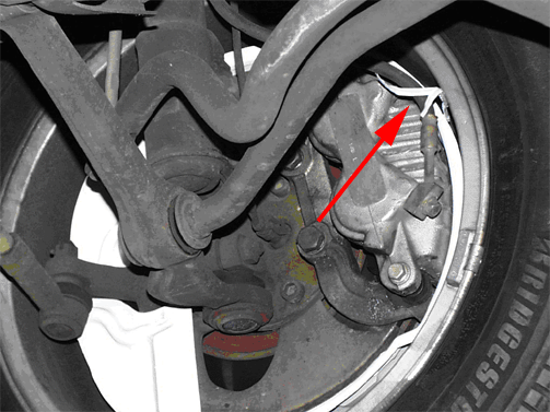
| 1. | With the vehicle on a hoist, locate the tie wire which should be wrapped around the caliper brake hose. This wire is located on the cover in a perforated area and will assist the
technician to tear the cover at this point. |
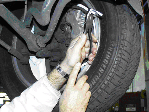
| 2. | Untie the tie from the hose, and using a pair of pliers to grip the tie wire, pull out and down to tear the wire through the disc cover. |
| 3. | Rotate the wheel while at the same time pulling the torn end of the cover away from the brake disc and wheel. Ensure that all material is removed and repeat for other wheels. |
| • | Front spring chock removal - front spring chock are found on all G8s. Raise the front of the vehicle using a garage jack or a two-post hoist. With the wheels at full hang, the chocks may be removed by pulling them out by hand. |
| • | Transit isolation connector - the transit isolation connector is disconnected prior to vehicle shipping to isolate circuits which require constant electrical drain. |
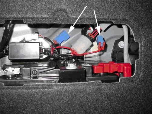
| • | The connector, which is blue in color, is located in the battery compartment within the vehicle trunk. |
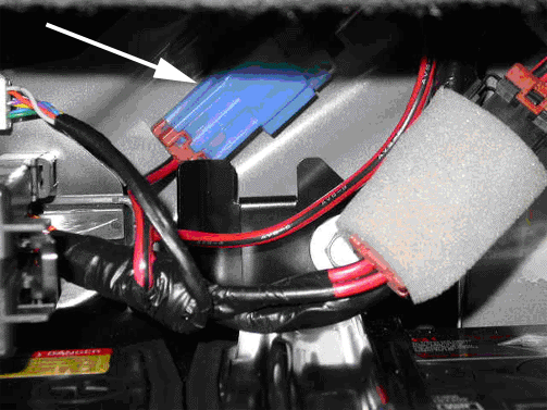
| • | Connect the two mating blue connectors to energize the affected circuits, including the radio, HVAC, supplemental instrument clusters in the IP center stack
area, IP cluster, sunroof (if equipped) and remote lock/ unlock. |
| | Important: It is critical that the two parts of the connector are fully assembled until a "click" is heard. The connector only connects one way. Pull on the connector with light pressure to confirm that the two connectors
(ends) cannot be easily separated.
|
| • | Battery charge inspection and recharge (if necessary) - battery damage may result from not being fully charged. The minimum charge required to ensure that damage does not occur is 12.3 volts. Immediately after the vehicle is received check
the battery open cell voltage across the battery terminals or jump starting posts in the engine compartment. If the vehicle is to be placed in storage for even a short period of time, assure the battery voltage is at 12.6 volts minimum. Battery voltage must
be above 12.3 volts when the vehicle is delivered to the customer. Battery voltage must not be allowed to drop below 12.3 volts during storage. |
| • | License Plate Installation - some states require a front license plate. |
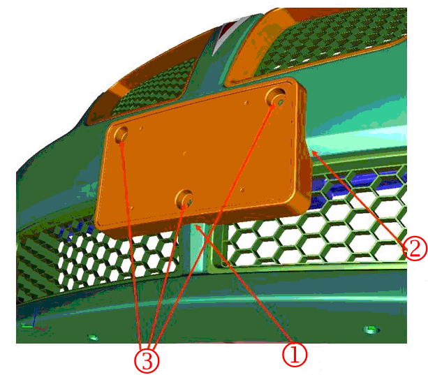
| • | The front license plate bracket is to be installed to the curved front fascia. Follow the instructions provided with the front license plate package. |
| • | Set the radio and clock time following these steps: |
| 1. | Press and hold the "Time" button on the radio fascia for more than two seconds. The display will show the "Set Clock" screen with the "hours" flashing. |
| 2. | Adjust the "hours" by turning the volume control dial. |
| 3. | To adjust the "minutes", press the menu control dial. The "minutes" will flash. |
| 4. | Adjust the "minutes" by turning the menu control dial. |
| 5. | Repeat this procedure for the day, date, month and year. |
| 6. | When correct, press the "time" button to save the changes. |
| • | Tire pressure - tires are inflated to 60 psi (413 kPa) in production. This will prevent flat spotting of tires when the vehicles is left in storage for prolonged periods. This is not suitable for normal driving. Ensure that this
pressure is maintained while the car is kept in storage but deflate the tires to pressures indicated in the placard on the rear face of the left hand front door opening prior to delivery to the owner. Tire pressures can greatly affect the handling of the
vehicle. Incorrect tire pressures are a main cause of owner concerns for vehicles that pull to the left or right and or rough ride. The tire pressures should be set to specifications using a tire pressure gauge prior to the car being delivered to the customer.
The new PDI process requires a test drive to insure the car does not have leads, pulls or vibrations when the car is delivered. The tire pressure and the road test odometer reading are to be recorded on the new PDI form. |
| • | Interior dome lights - prior to shipping, some early build 2008 G8s had the interior dome lights defaulted to off when the doors are opened. Be sure to push the (L) dome lamp activation button (car with doors open icon) before delivery to the
customer. |
| • | Tires - The base level G8 has a space saver spare tire , vehicle jack and jack handle. The G8 GT has an inflator kit only. Some vehicles may be equipped with summer-only performance tires. Summer-only performance tires are not recommended for
winter use. Refer to Corporate Bulletin Number 04-03-10-013B for more information on winter tires. |
| • | Verify that OnStar® (if equipped) is activated and operating properly. |
| • | Reset all MPH (KPH), MPG (L/100 km) and trip odometers settings to zero. |
| • | Vehicle rest reminder, DIC message and warning chime - this feature reminds the driver that they may have been driving too long without a break. After the ignition is turned on a counter starts and after two hours of continuous driving the
reset reminder flashes to alert the driver. The rest reminder reappears after another 20 minutes accompanied by a chime unless it was previously reset or the ignition has been turned off. It is recommended that this function be "Turned Off" in
DIC during the PDI process until the buyer becomes familiar with its usage. Owners Manual Section 4- under trip computer functions. |
| • | Exterior/IP lamp control switch - this one controls the functions of all the lamps, including the fog lamps. To turn on the fog lamps "pull" the switch towards you. The fog lamps will remain on until the switch is pushed in or
the vehicle ignition key is turned off. The IP dimmer controls are the two buttons above this switch. If you push and hold both brightness buttons at the same time, the night panel mode goes on or off. The "night mode" lights up the speed, information
displays and warning reminders while the rest if the IP lights are off. |
| • | Radio, Display Units, OnStar® and Cluster (IPC) service - these components are serviced through Authorized Electronic Service Centers (ESC) outlined in SPO bulletin GM P07-126 last issued June 2007. Technicians must program the odometer
mileage when replacing the IPC. |


